Andrey Skvortsov
-
Specific System Requiremens
01/05/2020 at 06:42 • 0 commentsOverall design notes.
Hardware:
![]()
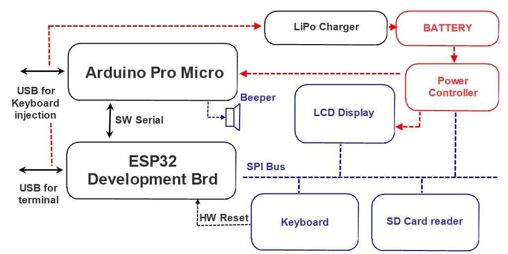
The main processor is ESP32 WROOM 32U. For the final version can possibly source a board with an in-built LiPo charger, such as GeeekNet https://www.seeedstudio.com/GeeekNET-ESP32-Development-Board-p-2945.html For now, the testing board is more conventional DevKitC.
ESP32 has been selected for two reasons. Firstly, it has excellent low-power features, allowing to save the battery. Secondly, the processor provides double-precision FP computations, which is essential for an engineering calculator. ESP32 can communicate to the PC via its USB port, WiFi and Bluetooth, so BASIC can be used from a PC terminal emulator - for, example, the user may want to enter and debug a complex routine by using the conventional keyboard and the big screen. The same USB port is connected to the LiPo charger / power supply (or will be using different ESP32 boards in the future - have not decided yet).
The main processor is connected to 4 peripheral devices via its primary SPI bus: the SD card reader, the 128x64 LCD display (may consider a different display although), the keyboard and the power controller. The latter allows the ESP32 to manipulate the LCD back-light, thus reducing the power consumption. It also controls the power supplied to the Arduino Micro Pro. The keyboard provides a hardware Reset button, which is needed to load programs into the ESP32.
The primary use of the Arduino Micro Pro is to impersonate a conventional keyboard/mouse for a PC (for example, for a text injection). The processor is connected to the ESP32 via Software Serial. Via the same interface, the ESP32 can send commands for a single-tone sound generation, such as beeps and simple melodies. As an alternative design, the LCD display back-light LED may be driven via the Arduino Micro Pro PWM output.Software:
1. BCL interface. In true tradition of retro calculators, this should be a comprehensive BASIC-system. All file system manipulations and other functions should be accessible from the BASIC command line (BCL). For example, to change the calculator mode from Radians to Degrees, the user switches into the BCL and types something like SET ANMODE DEGREES. To change the calculator precision and output pattern to scientific with 4 decimal places, one types, for example, SET NUMODE SCI4 The arithmetic expressions can be evaluated directly from the BCL, for example, ? 1e13/SIN(45) immediately evaluates into 1.175e+13. PRINT HUMODE returns the numeric code for the SCI4 constant: 14 (or rather 1.4e+01 as we requested a scientific format). Naturally, all standard BASIC commands should work in BCL as expected, e.g. 10 PRINT 1e13/SIN(45) returns OK and inputs the program line into the memory. The user should be able to use arrows to scroll the screen up and down beyond the 8-line boundary. At least 40 lines should be supported. Text selection and Copy/Paste function should be supported.
To make the system more practical, several additions to BCL are essential.
2. RPN interface. The screen displays three positions of stack: X, Y, Z. The total stack capacity should be about 20, plus an additional slot for the previous X value. The buttons should work as expected for an RPN calculator, e.g. pressing <1>, <9>, <.>, <7> results in X displaying "19.7". Then, pressing <Enter>, <2>, results in X displaying "1.970e+01" (remember, we are in sci-4 mode) and Y displaying "2". Pressing </> results in X displaying "9.850e+00". The previous X slot contains 2.000e+00. The RPN interface should be accessible from the BASIC programs. For example, the user wants to implement a program for calculating roots of a quadratic equation:
010 SET RPNLABELS "C (input)", "B (input)", "A (input)"
020 HALT RPN
030 A = RPNSTACK(2)
040 B = RPNSTACK(1)
050 C = RPNSTACK(0)
060 D = B*B - 4*A*C
070 SET RPNSTACK 2, D
080 IF D < 0 GOTO 130
090 SET RPNSTACK 0, -(B+SQRT(D))/A/2
100 SET RPNSTACK 1, -(B-SQRT(D))/A/2
110 SET RPNLABELS "Root 1", "Root 2", "Discriminant"
120 GOTO 160
130 SET RPNSTACK 0, -B/A/2
140 SET RPNSTACK 1, SQRT(-D)/A/2
150 SET RPNLABELS "Real part:", "+/- Imaginary part", "Discriminant"
160 HALT RPN
170 GOTO 10
To solve quadratic equations, the user goes to BCL and types CHAIN QUAD <Enter> (assuming QUAD.BAS is the program name). The system presents the user with the RPN screen, there instead of labels "X", "Y", "Z" are labels "C (input)", "B (input)", "A (input)". The user operates the RPN to fill the data and presses <Run> button. The system displays the answer in "Root 1", "Root 2", "Discriminant" form. To proceed with the next computation, the user presses RUN, and gets labels "C (input)", "B (input)", "A (input)", etc. To terminate the program, the user presses <Halt> button, and the labels change back to "X", "Y", "Z". The program remains in the memory and could be restarted by pressing <Run> button or by going to BCL and typing RUN <Enter>.
3. EDT interface. In this mode the system allows a direct edit of the program (note that LIST command on a 8-line screen is very inefficient, and even on a large screen is limited). The expected user interaction is similar, but not identical to Windows Notepad editor. NEW, LOAD and SAVE functions are available in BCL and should not be duplicated here. Find, Replace, Copy/Cut/Paste, Move Line Up/Down should be available in the EDT interface. A text "wrap" and "no wrap" modes should be supported. Besides the BASIC files, the same editor may be used to view data files, make quick notes, etc.
4. DIR interface. In this mode the user can traverse the calculator file system. Note that FILES command on a 8-line screen is extremely inefficient. The typical use in BCL would be as following. The user wants to save the file in a certain folder. In the BCL, the user types SAVE <Space>, then presses <Dir> button, navigates to the folder and selects the file name. Pressing <Enter> on a file name, for example, QUAD.BAS, results in the system returning into BCL mode and SAVE QUAD.BAS appearing instead of SAVE. At this point, the user may edit the name, for example, to SAVE QUAD_2.BAS and press <Enter> to complete the command.
-
Hardware Mock-up Completed
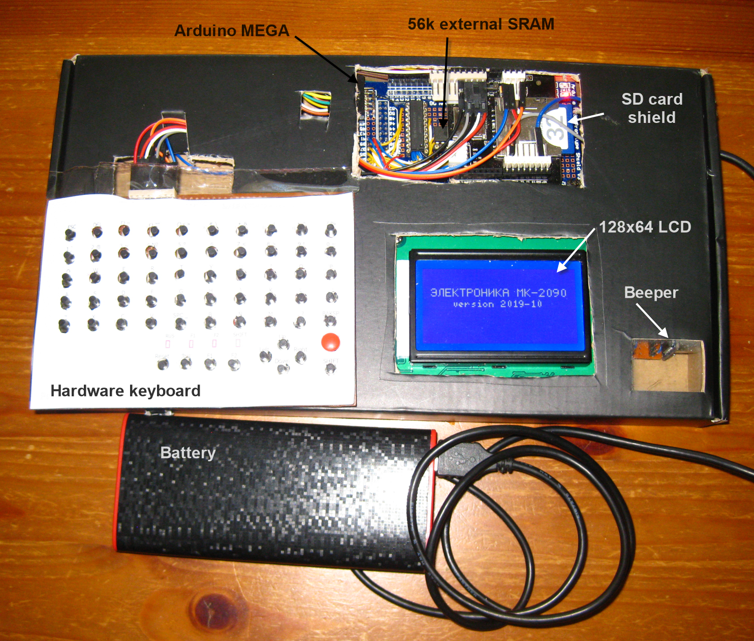
10/24/2019 at 03:45 • 0 commentsFull hardware mock-up is now operational (yes, it is damn ugly).
![]()
The current mock-up version is based upon:
(1) Arduino MEGA 2560
(2) Arduino MEGA SRAM shield (my PCB is modified for 56k RAM instead of 32 in the original version) https://hackaday.io/project/21561-arduino-mega-2560-32kb-ram-shield
(3) Arduino SD card reader; this version is for Uno, but runs on Mega with pins 10-13 using Soft SPI (library mods by David Mellis). Note that the standard SD library will not work if the classic Uno shield is transplanted to MEGA:
https://github.com/ptravnik/Retro_CALC/tree/master/SD2
(4) Piezo speaker on line 9
(5) Hardware keyboard on lines A0-A4. The driver is here (check the Morse code example!):
https://github.com/ptravnik/Retro_CALC/tree/master/HWKbd
(6) LCD screen 128x64 pixels on SPI. The driver is U8g2 from Oli Kraus (it writes Cyrillic and other character sets):
https://github.com/ptravnik/Retro_CALC/tree/master/U8g2
The keyboard PCBs have been ordered from https://www.elecrow.com/ Apparently they have been already manufactured and are in the mail. Hopefully I will have something less ugly in a couple of weeks. The order files are here:
https://github.com/ptravnik/Retro_CALC/tree/master/HWKbd/KiCAD
All hardware has been tested and fully operational. Now the next step: LCD terminal and RPN calculator part. -
Hardware Keyboard: Working Prototype
10/11/2019 at 06:31 • 1 comment![]()
I have completed the keyboard design. The current version has 60 buttons (one is hardwired to the controller Reset).
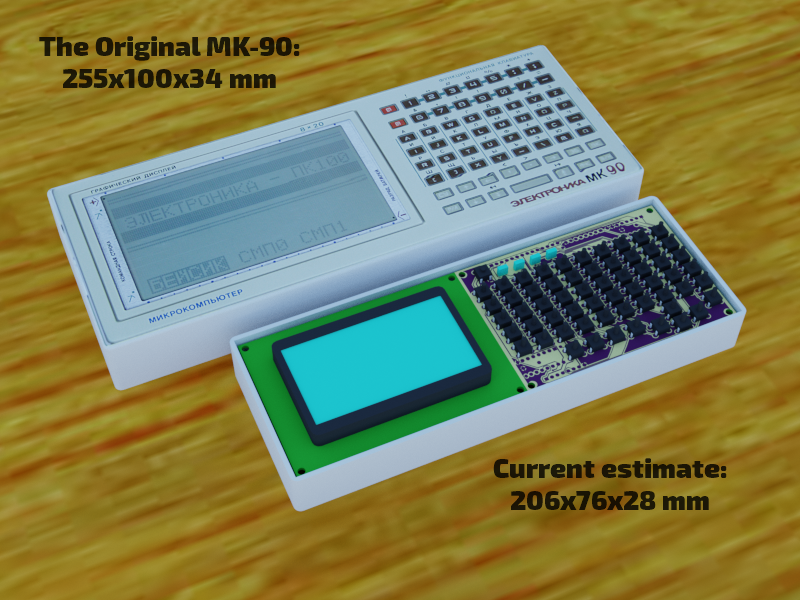
The display so far is a Black-and-White 128x64 low-power Black-on-Blue LCD (Note that the original MK-90 has exactly that resolution, but the screen is much larger). This is a quick rendering for comparison:
![]()
An alternative version would be with something like <A href="https://ru.aliexpress.com/item/32900230382.html?spm=a2g0o.productlist.0.0.74332b554sPNai&algo_pvid=9cab2e0a-fd50-41b0-bcb1-1507db69df45&algo_expid=9cab2e0a-fd50-41b0-bcb1-1507db69df45-16&btsid=be79cb74-3b32-40fb-b934-aadc62349cf5&ws_ab_test=searchweb0_0,searchweb201602_9,searchweb201603_55">LG320240</A>, but they are very costly.
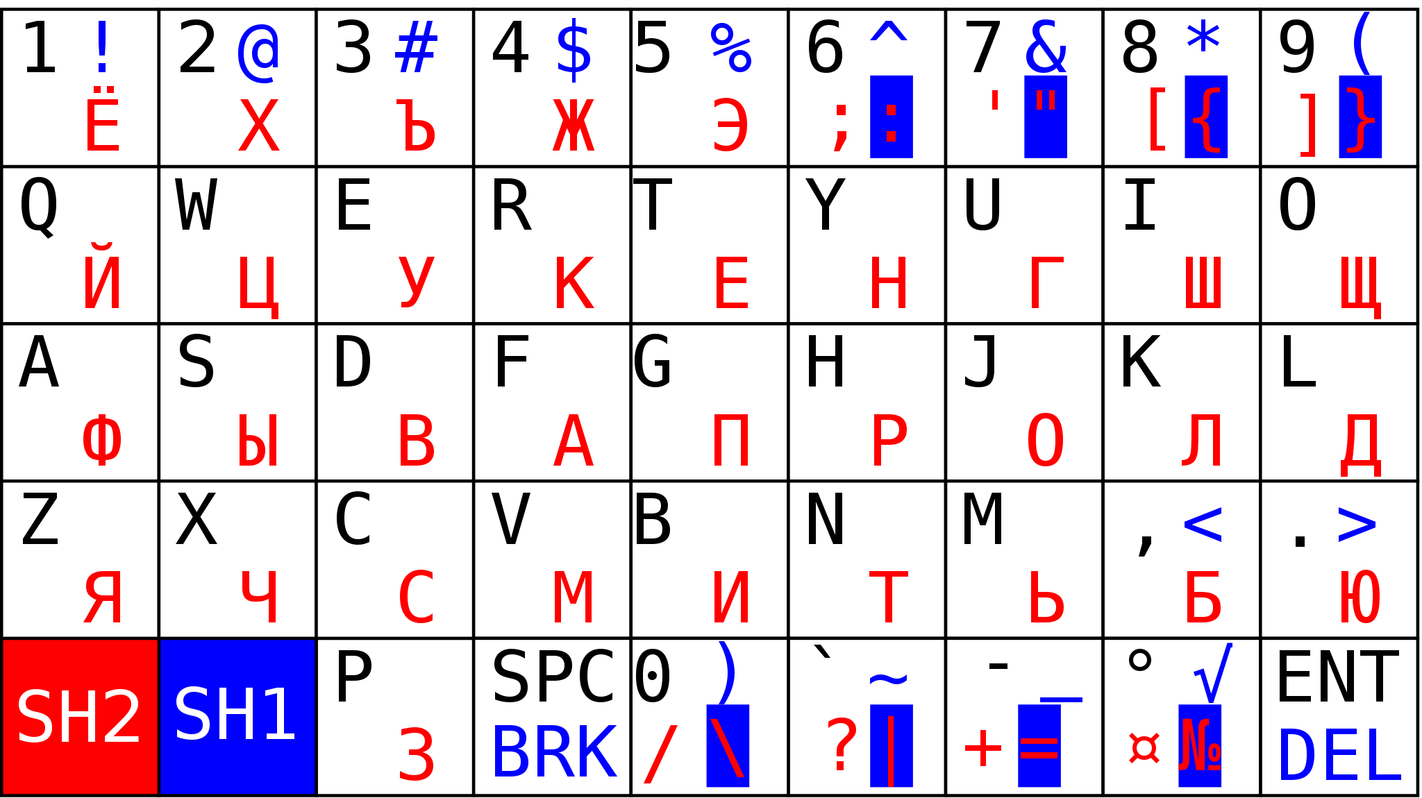
The keyboard is assembled on a 140x95 mm mock-up board (the actual PCB size will be 100x70). The electronics and the Arduino Mega driver are working, Now need to decide how to assign the letters...![]()
The schematics is attached in the PDF file.
The keyboard will have 6 rows and 10 columns, 59 buttons in total (#60 is used for reset). It is operated via a 3-line interface not very dissimilar to SPI: setting RESET high brings the counters to the initial state, then CLOCK is cycled 59 times and SIGNAL reads the status of 59 buttons (HIGH means "pressed"). The CMOS 4017 decade counter addresses 10 rows and a combination of a 4520 binary counter and a 4051 analogue mux connects the rows. The clock signal is sent to the 4017. Upon reaching back to zero after 10 pulses, the ripple signal from the decimal counter advances the 4520 to the next row. Because only one button is connected between the mux and the decimal output at any given time, diodes at the buttons are not required. Any number of buttons can be pressed simultaneously (the number of your fingers - and toes - is the technical limit) - they will all register .
The second half of the 4520 octal counter drives 4 LEDs to show the keyboard status (or could be used from the Basic to do some creative blinking). One button is hardwired to ESP32 reset.In the stand-by mode the keyboard consumes less than 10 uA (micro-amp). Each LED consumes about 1200 uA if lit.
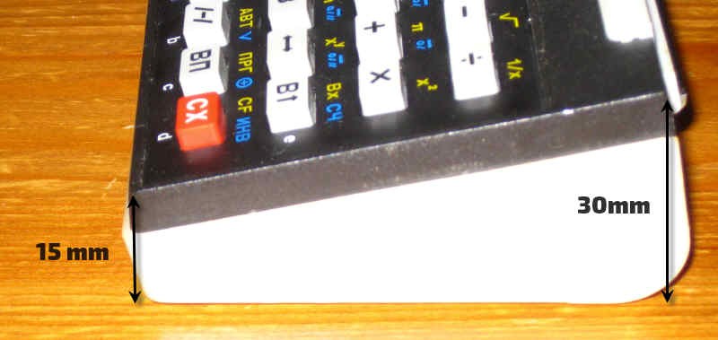
Upon the PCB completion and testing I will put the KiCAD files on Github.The next big design question: "To brick or not to brick?"
MK-90 is, well, a "brick". Another status symbol, MK-52, is a "wedge" (an so are B3-34!):
![]()
-
Thoughts on matrix keyboard
05/06/2019 at 16:09 • 0 commentsHere is a first variant of matrix keyboard. I choose 5x9 size as the smallest suitable to support full cyrillic charset and digits on separate keys (33+10).
![]()
It will use 2 shift keys: the red shift and the blue shift, which state will be indicated by the 2 LEDs of corresponding colors.
-
Simple structure
04/03/2019 at 11:41 • 0 commentsFirst prototype will consists of minimal number of modules:
![]()
-
Firmware is almost done
03/31/2019 at 23:59 • 0 commentsThe firmware is a Terminal-BASIC with UTFT output driver.
Things to be done includes support for double precision floating point arithmetics (DUE has double reals unlike 8-bit AVRs). and driver for a matrix keyboard of 45 - 48 keys.
Terminal-BASIC programmable calculator
A poket-to-laptop size microcomputer/programmable calculator, based on Terminal-BASIC