Close
0%
0%

MPRT - Modified planetary robotics transmission

The reduction of strain-wave, but using a 'single' stage planetary gearset.

Similar projects worth following
This is a compact, 'single' stage planetary gearset where the output is derived from a second ring gear varying a few teeth from the primary.

With the initial model of 18 sun teeth, 60 ring teeth, and 3 planets, this resulted in a 'single' stage gear reduction of -82.33:1.
A regular planetary gearset of this size would have a reduction ratio of 4.33:1.
That is a whole lot of torque in a small package.

The design is thin, flat, equal height for the gear stages, and nearly all of the force is applied right at the edge. That would lend itself really well to being laser cut and driven with a pancake BLDC motor. The ability to use larger teeth and a larger sun gear also works well for 3D printing.

So this begs the question. Wanna build a robot with this? Let's collaborate...

Using it!

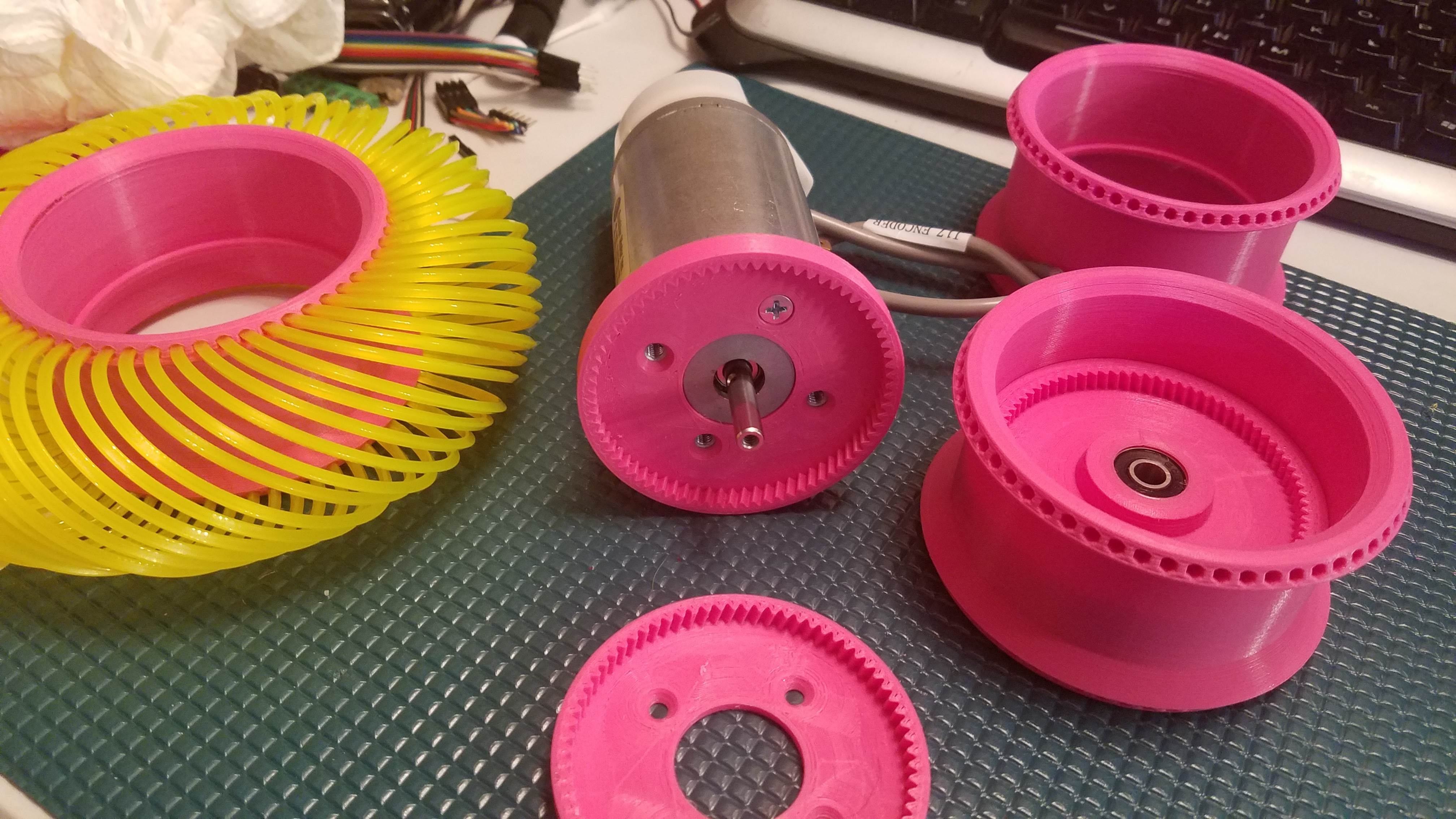
I've decided I need a transmission for testing out the #FilaMecanum concept, so this is going to be it.

Background

First I think I need to explain how a normal planetary drivetrain is constructed.  

The power input turns the sun, and the sun drives the planets which rotate within a stationary ring gear.  The planets are mounted to a carrier with bearings, and the carrier is where you take your output.  

This arrangement gives you a gear reduction of:

To get further reduction, you can add more stages just like the above, all sharing the same ring gear.  The stages multiply, so 3 stages of 3:1 would give you a 27:1 reduction.  Problem here is now you need 9 planets, 9 bearings, 3 suns, 3 carriers, and 3 times the height too.

If you try to get more than about 3:1 reduction per stage, you end up needing fine teeth and a small sun gear.  Small sun gears don't survive very long unless made of some heavy duty stuff and so 3D printing/laser cutting that doesn't work so well.

How this works

The power input turns the sun, and the sun drives the planets which rotate within a stationary ring gear.  So far the same.

However, instead of taking your output from the planets, we allow the planets to just rotate within the ring, and cover them with a second ring gear.  The second ring gear is constructed to vary from the stationary ring gear by exactly numplanets teeth.

Now, on each revolution of the planets the two ring gears will advance with respect to each other numplanets teeth.  We take our output as the second ring gear and get massive gear reduction from it.  

This arrangement gives you a gear reduction of:

The result:

  • We can now use a much larger sun gear to drive the planets, and still get significant reduction.  Perhaps even wrap the perimeter of a BLDC outrunner.
  • We only need one bearing, which essentially supports the joint itself.
  • The vast majority of the force applied to the joint is right at the outer edge of both ring gears and drives both in opposite directions at multiple locations.
  • We can get away with using much cheaper materials to do it.

Picking a compatible gear ratio is critical, so here are the rules for the math required for the gearing.  The simplified version for 3 planets is use a multiple of 6 for both the sun and ring gear teeth, and then an output ring gear tooth count of ringteeth - 3.

And here is a video.

2019-05-10-153016.webm

video of the laser cut MPRT

Open Web Media Project - Video - 4.57 MB - 05/10/2019 at 07:39

Download

MPRT-1.01.scad

Fully parametric, minimal version

x-openscad - 6.13 kB - 05/10/2019 at 07:09

Download

involute_gears.scad

Put in same directory as MPRT.scad

x-openscad - 18.16 kB - 05/10/2019 at 07:10

Download

MPRT-2.dxf

Elbow design

AutoCAD DXF - 1.69 MB - 05/04/2019 at 14:28

Download

MPRT-1.dxf

360 plus laser cut design

AutoCAD DXF - 2.32 MB - 05/04/2019 at 14:28

Download

View all 18 files

  • Printing, a lot.

    MasterOfNull05/17/2019 at 22:51 0 comments

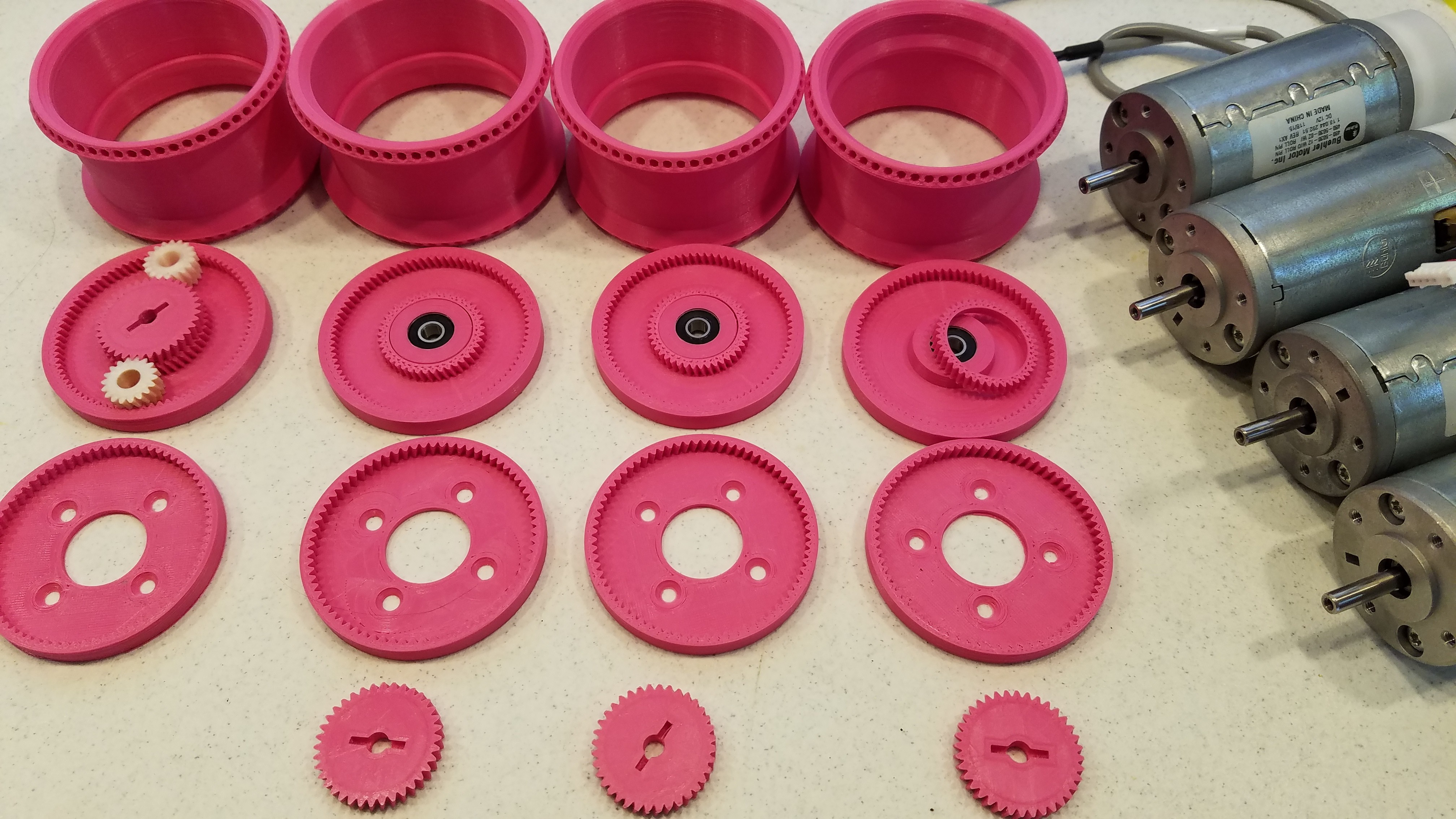
    The parts I needed to use this for the #FilaMecanum project are back to printing after a little battle with some printer issues.  About 70% of my four transmissions are done, but I still don't have a single one actually assembled.

    I have been saving the planets for last as I am going to do those in nylon, and I don't have a lot of that to waste on purging.

    <EDIT> All the PLA parts are done and I started on the nylon ones. 

    Some flailing ensued, but I'm now printing them.

    </EDIT>

  • The End Game

    agp.cooper05/12/2019 at 03:19 8 comments

    The End Game

    A project has to have an "end game" to steal the concept from Chess. There comes a time not to "chase the rabbit down the hole".

    While laser cutters are very precise, they still have the same accuracy issues common to CNC mills.

    Accuracy versus Precision

    When I was young a had a wind up wrist watch. My watch had a second hand, but it usually off by about 5 minutes a day. So it has a precision of 1 second but an accuracy of 5 minutes. Think about this as it is important!

    CNC machines are very precise, usually better than 1/100 of a mm, but how accurate are they? That depends on many things and how hard you drive them.

    When I first started using my CNC mill, I drove it hard and fast. The result was that my circle cut outs were visibly oval in shape and not to size (at least a 1 mm too small).

    When using CNC machines, it is necessary to slow down and reduce the depth of the cut (to unload the machine) and to compensate for the cut (i.e. conventional or climb cut etc) if you want accuracy.

    What I have noticed in the videos of the laser cut gears is that they suffer the same problems (but not so bad) as my gear box. Their gears are also noisy and wobble around.

    What this tells me is that laser cutters do not have the accuracy necessary to cut very fine gear teeth. Laser Cutting Services are going to run their machines fast as most clients don't have the need for high accuracy, especially in "Z".

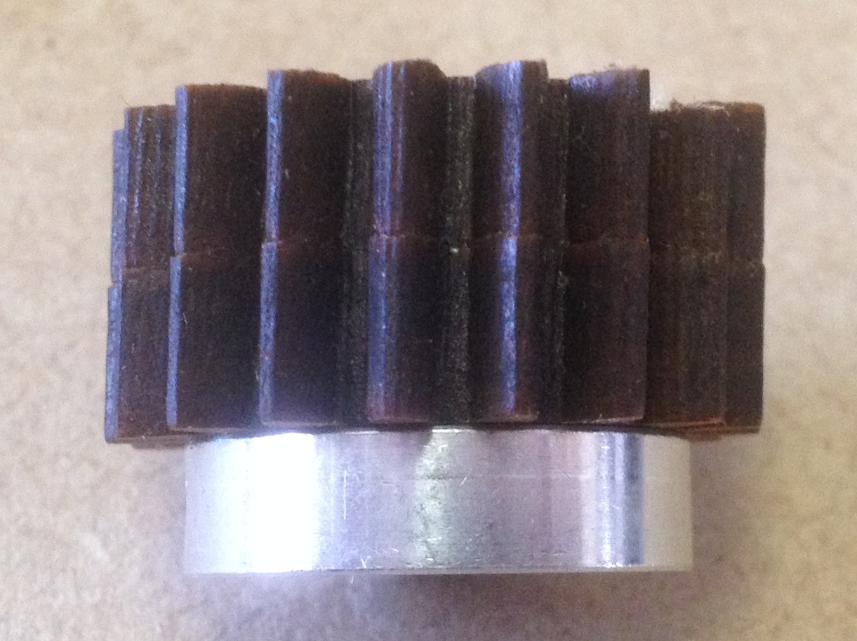
    You can see from the image of the sun gear that the teeth are cut very precisely:

    That is at least to 1/10 of a millimetre. But the not very accurately, tilted.

    Another Laser Cutter Service Provider

    I seek out another laser cutter service provider. The one uses a bigger machine and is more expensive (~50%). But her can cut 6 mm plywood and acrylic. Nice.

    The kerf for his machine is about 0.3 mm versus about 0.15 mm for the previous service.

    Backlash Still Too High

    The backlash for my gear box is less than one degree (which is not too bad) but far too high for my intended application (a SCARA elbow). Although I can improve the accuracy of the gears by making the teeth bigger (i.e. change the diameter and gearing ratio of the gear box), and using another (hopefully more accurate laser cutter service provider), the backlash for the gear box will likely still be too high.

    There are still options that can be pursued. One thought is a lantern design:


    Here the accuracy is determined by the location of the socket and pin holes. The machine would very lightly loaded drilling (rather than cutting) these, so likely to be more accurate (than cutting). The pins themselves are very accurate.

    One advantage of the lantern design is I can cut  it with my CNC machine.

    But, for my application I think I may be better off exploring a belt drive and custom belt gears. Time is an issue as well.

    AlanX

  • Laser Cut Original MPRT Version

    agp.cooper05/10/2019 at 03:59 3 comments

    Laser Cut MPRT

    The irony that I am building Daren's design and Daren is build my design has not escaped me!

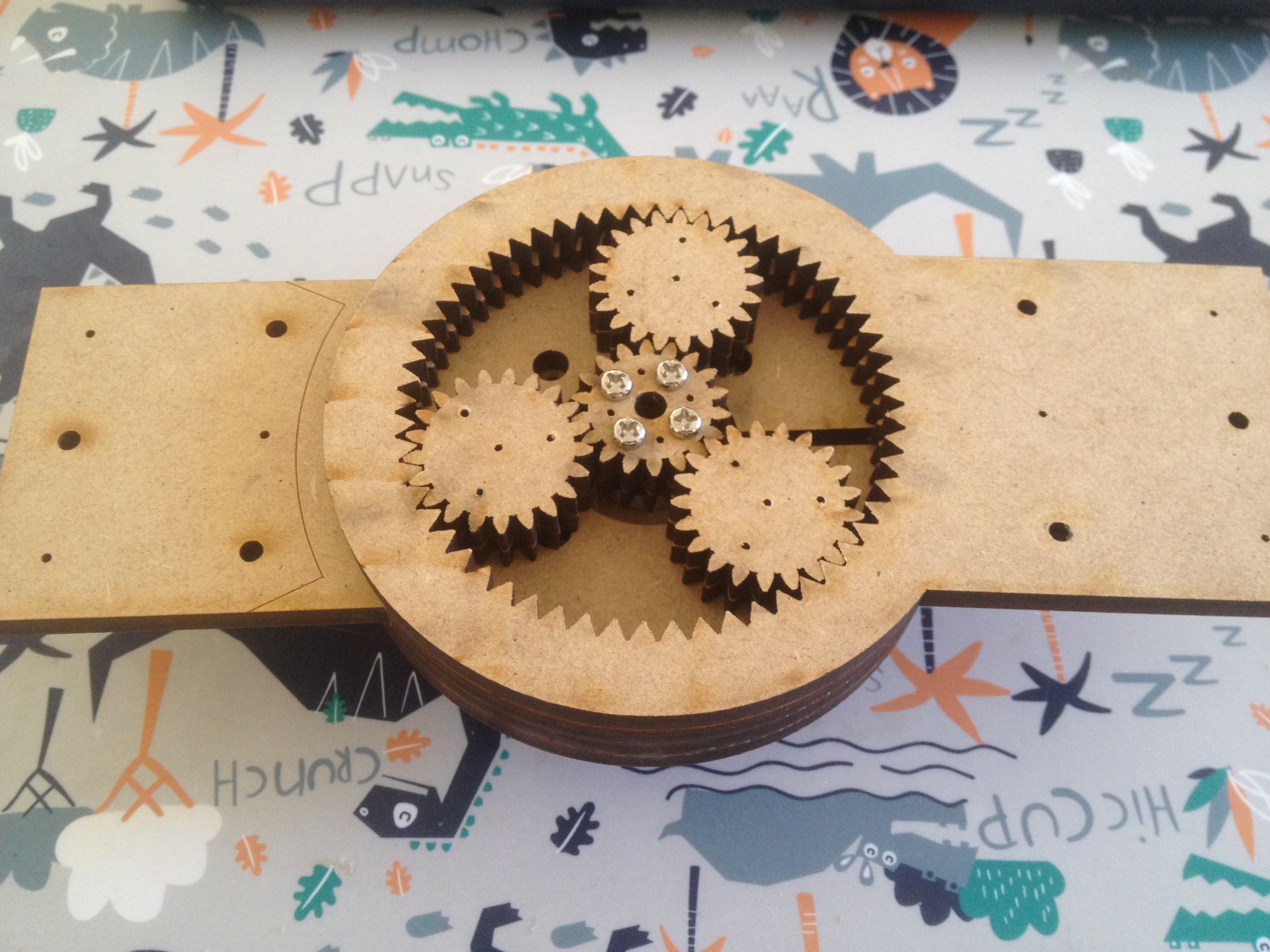
    I have got back the laser cut original MPRT:


    Now the fit is not overly tight (the laser cut width varies from top to bottom is more that the assumed 0.1 mm width. However the movement is less than a degree.
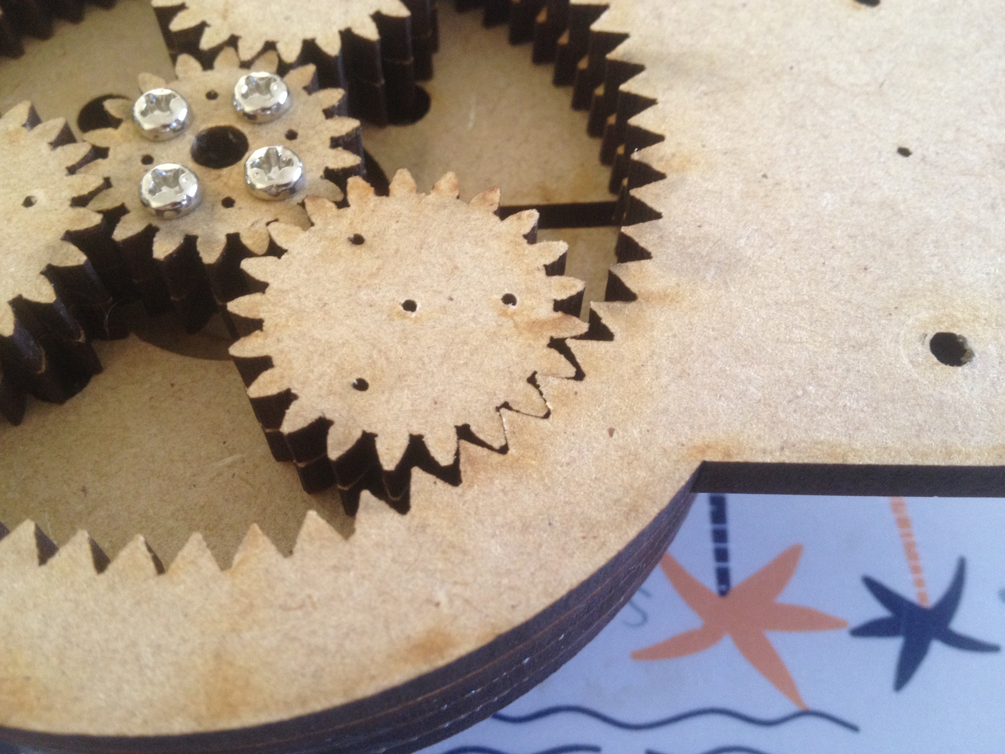
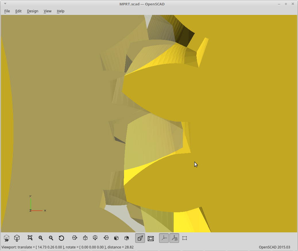
    Here is a closeup of the gear fit:

    Now your can't expect better than that! It does move, perhaps 0.5 of a mm.

    When I sent the design off to be cut I had not resolved what to do with the protruding star bolt heads. I should have just cut a hole in the retaining cover. But today I will just drill out or counter sink the bolt heads in the star gear.

    The Result

    My gear cover need work and the star gear is off-centre. Not sure why, changed the hub and still off-centre. May be a design fault or bad alignment or problem with the laser cut (it is not that accurate even visually).

    But I did get it working, sound like it is grinding sand. Wobbles a lot and sometimes stops for a moment and then restarts.

    I have uploaded a video into the files area.

    The result is it need more work.

    Review

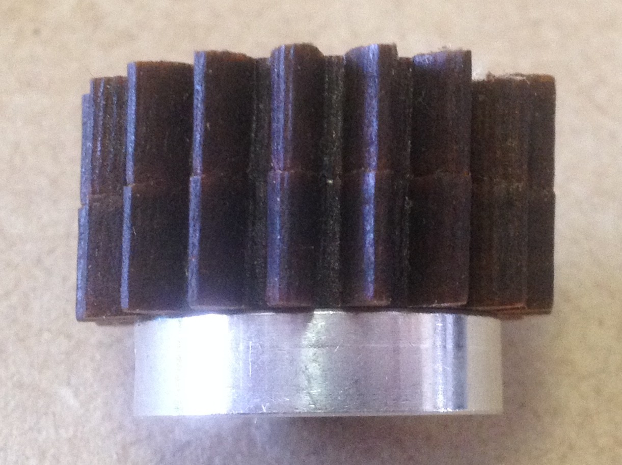
    I pulled the gear box apart this morning. The axle and hub are true. There is a slant to the cut on the sun gear. This is a problem I have had before with this laser cutter service but I had not had to rely on the edge so it is was not important then. Gluing the gears together make the problem worse. I tried measuring the slant and it is at least 2 degrees:


    May not sound a lot but it is too much for a gear box.

    If I pursue the laser cut gearbox, I will have to find another laser cutting service and there has been for a long time only one that is "retail".   

    AlanX

  • Latest

    MasterOfNull05/09/2019 at 23:30 8 comments

    Cleaned it up, and uploaded the latest.  

    Fully parametric, no inherent extra backlash, and now with minimal extra stuff.  

    The goal now is to have this properly 'included' into other things, and then have you further modify the base transmission parts there instead of trying to make this a 'one stop shop'.  That will take some research as I'm more of an abuser of OpenSCAD than a user.

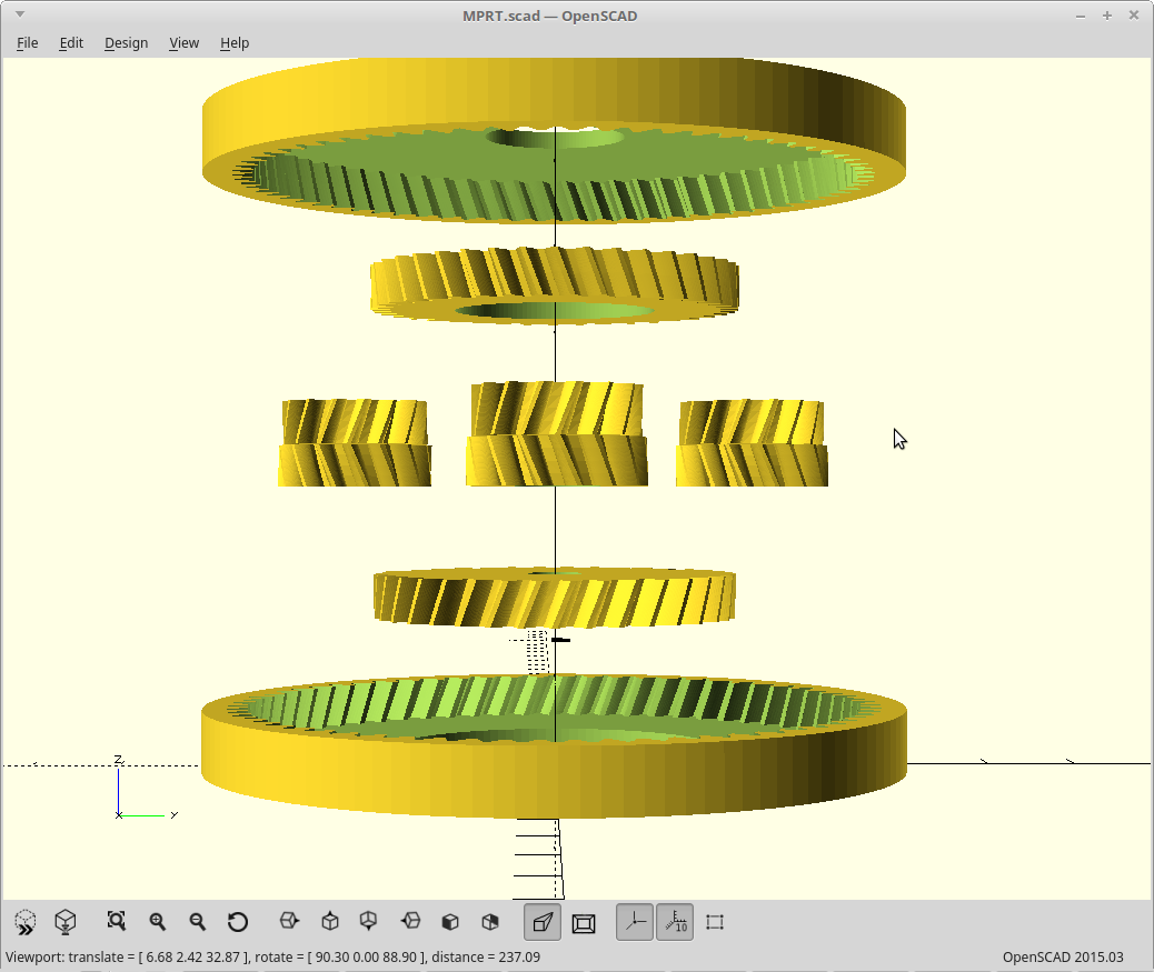
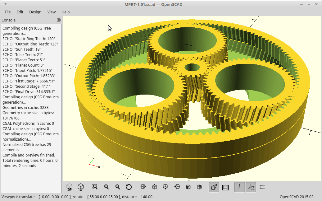
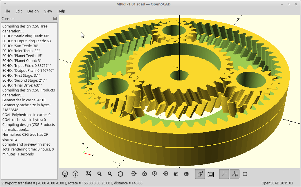
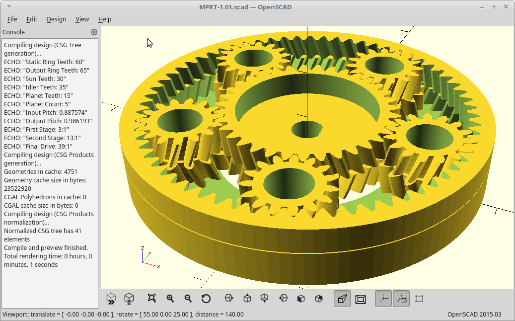
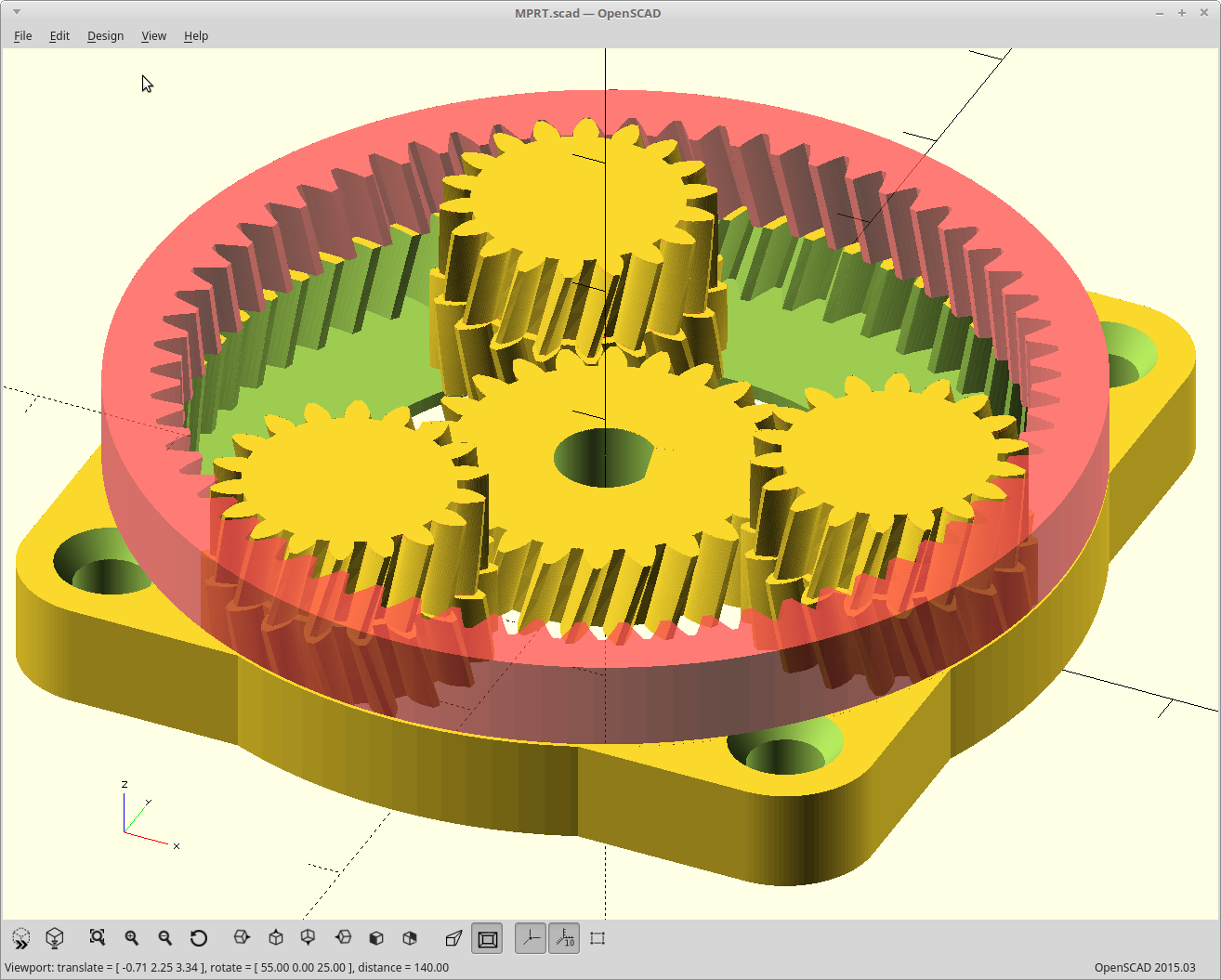
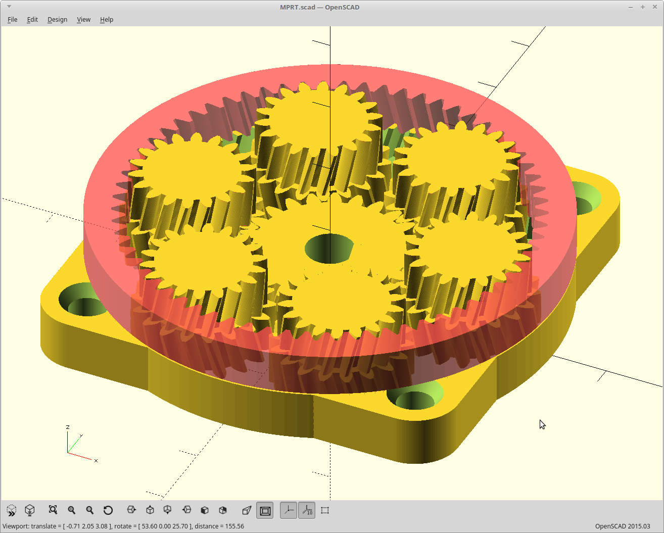
    And now, some eye candy.  

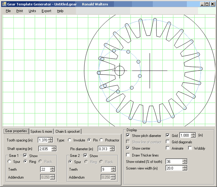
    If you look in the console part of these images, you'll see the numbers used to generate these and the resulting gear ratio. 

    <EDIT> I forgot to mention.. all that was changed in the source to render these three different transmissions was the ring_teeth, sun_teeth, and planet count. Everything else was parametric and scaled appropriately. </EDIT>

  • I can't be that lucky..

    MasterOfNull05/09/2019 at 20:43 2 comments

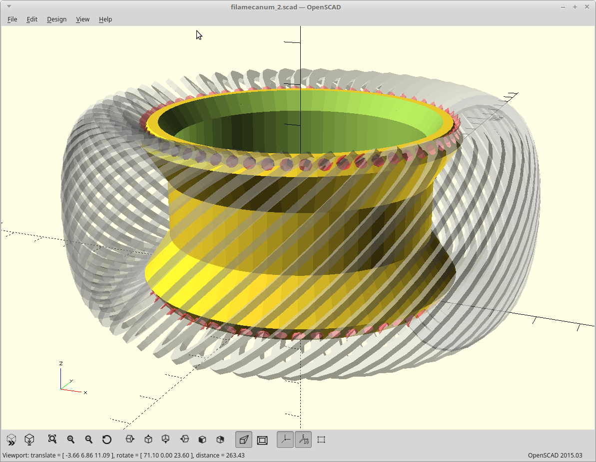
    For kicks I decided to add an idler gear. This is one way to prevent the output ring from pushing in on the planets. 

    Either I'm incredibly lucky, or there must be something happening with the math here that I don't understand that makes this work.

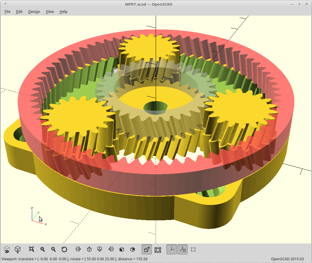
    It fits perfectly.  The idler as shown here is the gray transparent one.

    I just used the output pitch, and added 3 teeth to the sun.

    It's gotta be the math, but I had no idea it would be that easy.  I'll be using that.

    I will need to adjust the model to have more squat gears though so I still have room for 2 6mm tall bearings on my motor shaft.  Working on it.

    <EDIT> I also just realized how to solve for the actual output pitch required here.  Yay!</EDIT>

  • Perfect pitch

    MasterOfNull05/06/2019 at 08:05 11 comments

    Finally got around to generating a version where the input and output gear pitch matches the corresponding layers, aka split planets.  Here it is, with a twist.

    I generated the above with zero backlash allowance, just to make sure all the teeth were meshing appropriately.

    It works with 6 planets as well.

    I think that may be a bit much though.

    I'm still missing the calculation for one number, and so the code contains a fudge factor I need to eliminate yet before it's fully parametric and gets uploaded.

    Now to add this to the #FilaMecanum project..

  • Original MPRT Laser Cut Design

    agp.cooper05/04/2019 at 03:39 5 comments

    Original MPRT Laser Cut Design

    It is the original design concept (including gear ratios) but with the optimised output ring.

    The optimised output ring has been trimmed to meshes properly. It should have less backlash and gear "movement".

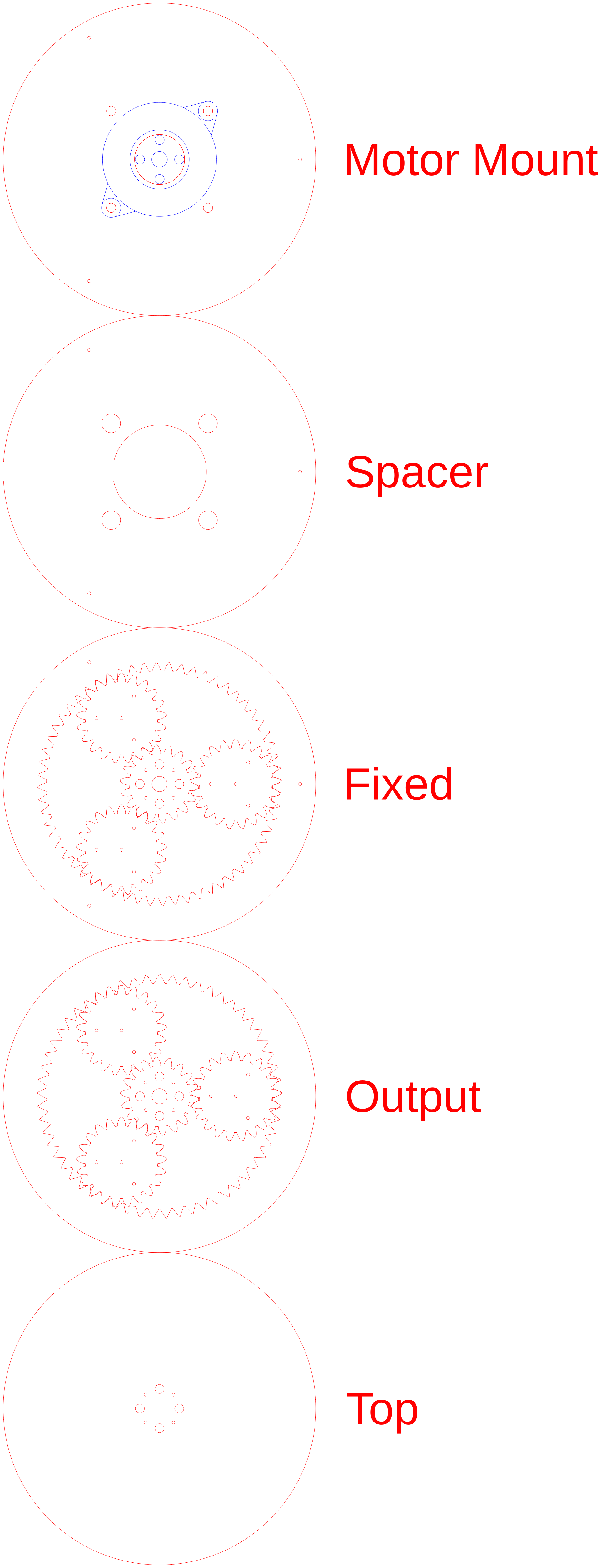
    It has taken a while to work out how to design a layered build up suitable for a laser cutter.

    The main problem was that the stepper motor shaft was too short (only 14mm) and cannot be used (without some sort of extension) to retain the gears. The solution was to extent the height of the sun gear.

    Two designs versions will be presented:

    • a 360 plus rotation version, and
    • an elbow version.

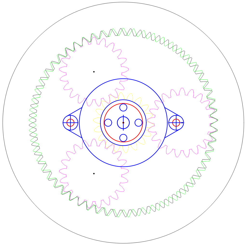
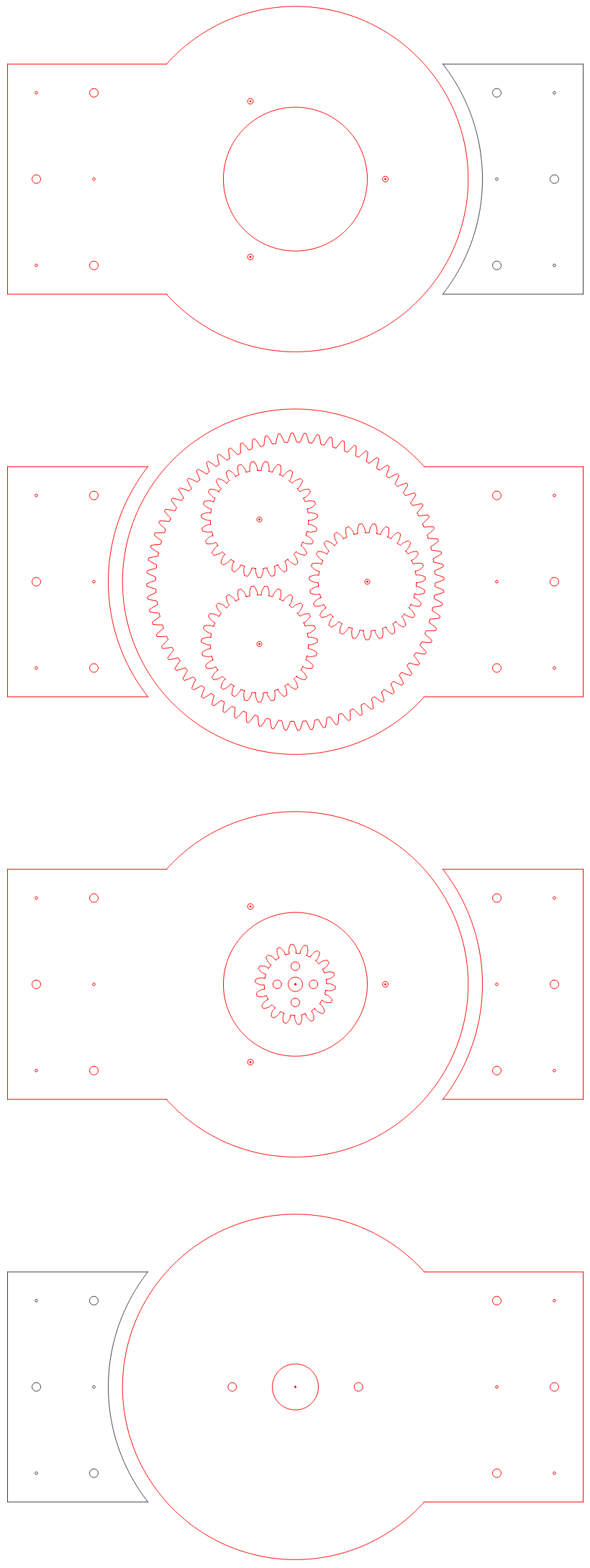
    Here is a top view of the stacked gears:

    Notes:

    • The stepper motor (blue) is mounted to the bottom or first layer.
    • The sun mounting hub and stepper motor mounting bolt heads are on the second layer.
    • The second layer also has to make access provision for setting the hub grub screw.
    • The next layer will have the sun, planets and fixed ring.
    • The next layer will have an extension of the sun and planets, and the output ring.
    • The top layer will have a retaining disk either attached to the sun gears for the 360 plus version, or attached to the fixed ring for the elbow version.

    Really what you should look at here is how well the gears mesh!

    The 360 Plus Version

    The main thing not to like is that the end cap rotates at the same speed as the stepper motor and the hub holds it in place.

    Notes:

    • The slot in the spacer disk is to access the hub grub screw.
    • The really small holes are for alignment.
    • Where necessary, the cutout has been adjusted fro a 0.1 mm laser cut width. 

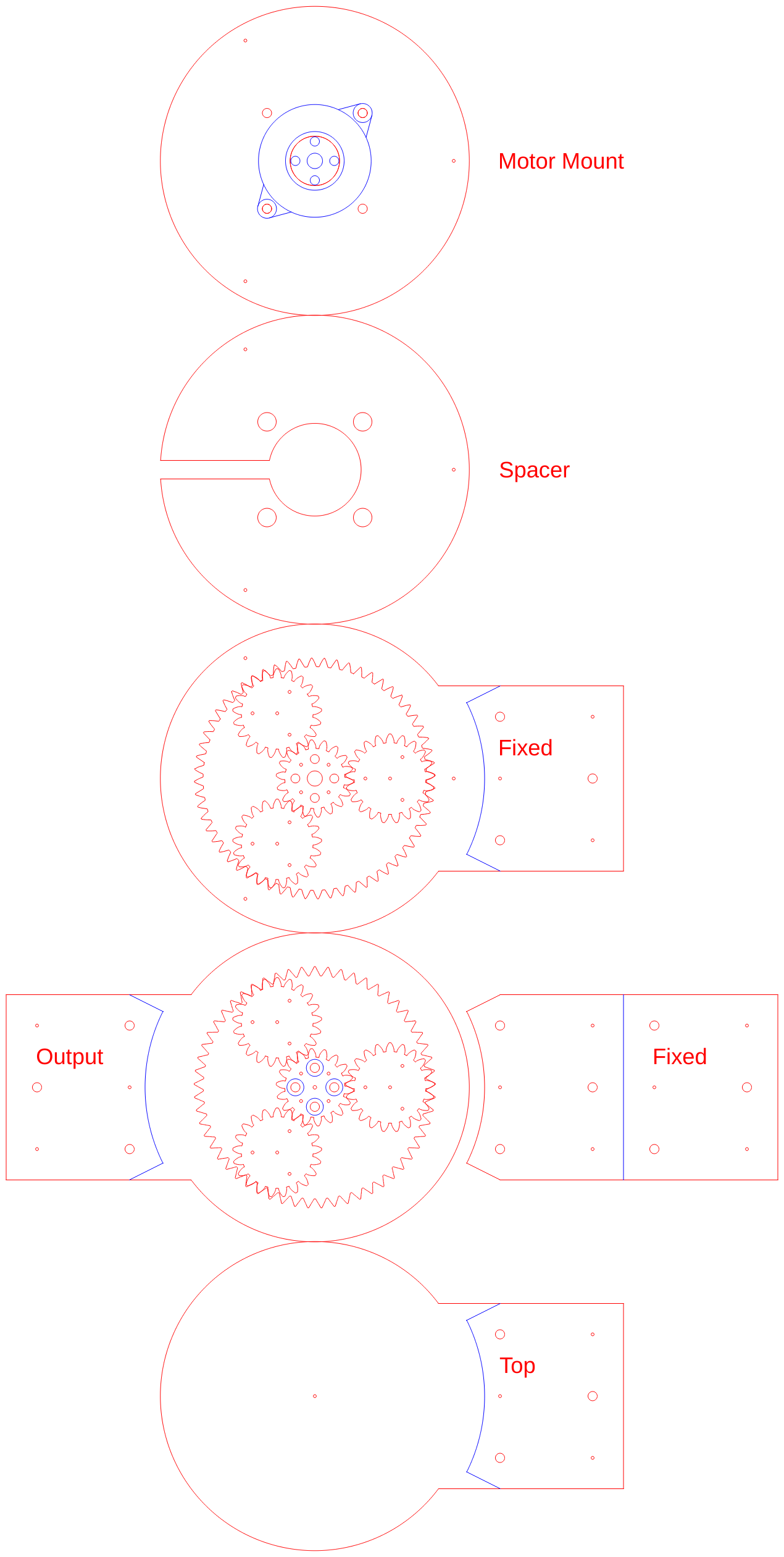
    The Elbow

    The elbow is similar except the top is fixed (similar to the single stage planetary gear design). The top just holds the gears inside the housing. Here is the laser cut design:

    Notes:

    A bit of trouble with the star gear mount bolts (to the hub). They stick up and interfere with the top. The gear is not big enough to laser cut cut holes (~6 mm diameter) for the bolt heads. I can lower the star hub about a 1 mm, more than that I have to increase the size of the motor mount locating hole (not ideal). I can (post laser cutting) counter the bolt heads.

    I put a small dowel in the top later that can be used to minimise movement of the star gear.
    Like Daren's original design there is no carrier.

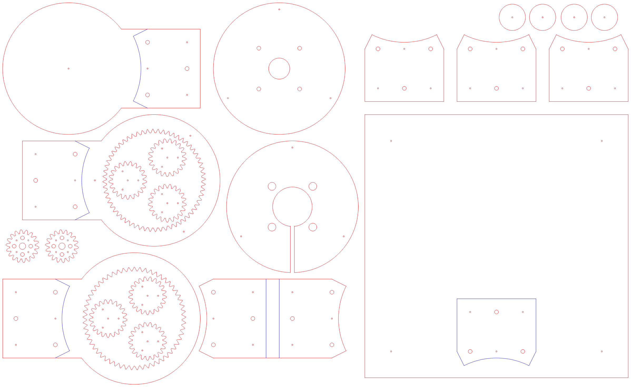
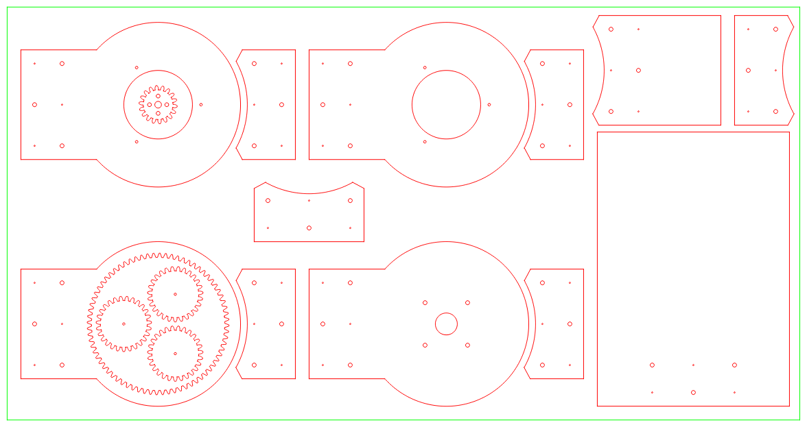
    Laser Cut Layout

    Hers i the laser cut layout:

    On the left is the elbow and on the right is a stand/platform.

    It has been submitted for a quote (usually about A$65).

    AlanX

  • Purpose!

    MasterOfNull05/04/2019 at 00:50 0 comments

    I had another idea a whole 48 hours ago, and that became the #FilaMecanum project. Basically that project is a robotics mecanum type wheel, but instead of using rollers it uses filament.  It should also work better than the original wheels on soft/uneven surfaces, and is cheap and 3D printable.  I didn't have a defined purpose for that project either.  :)

    So I just made a version of that which will fit some motors I have, and I'm going to make a version of this transmission to power it.

    The motors are pretty beefy with a 100w continuous rating, but run at a completely unusable rpm range for robotics of 3k rpm.  This will make them usable.

    I'm now going to take the time to generate the split planet version in OpenSCAD first though, as it has some definite advantages for this.  The most important one being that if I can use a half-height sun gear, then I can put two bearings on the shaft and support the output ring gear/the wheel itself that way.  This is going to be fun.  :)

  • Laser Cut Single Stage Design

    agp.cooper05/02/2019 at 11:06 2 comments

    Laser Cut Single Stage Design

    I was having problems working out the full MPRT laser cut design so I thought I would try a single stage design first. It is not that I could not design a laser cut  MPRT, it is just that I was not happy with the design (i.e. too many layers). I know it can be better.

    Actually even the single stage design was tricky. But eventally here it is:

    The gray components are not necessary but useful for mounting.

    So what we are looking at, starting at the bottom:

    • The motor mount (the fixed arm), for different steppers I should add at least two more holes.
    • The carry ring or output arm, (sun gear is actually on the next slice)
    • The fixed ring and planets (offset for cutting)
    • The upper carrier ring.

    Notes:

    • The gears and bolt hole have been adjusted (where required) for a laser cut width of 0.1 mm.
    • The bolt holes are for M3 bolts but the final construction assumes the layers will be glued.
    • It has been assumed a 2 mm dowel fixed to the planet will rotate in the carrier.
    • And finally, the really small holes are for alignment pins (1.2 mm diameter by 25 mm long nails).
    • The gear design is 5 turn (input) to 1 turn (output) for the single stage.
    • I will wax the wood to reduce friction, may need to add a paper spacers to free up rotation of the carrier.
    • The MPRT version (based on the current gear set) will be 55 to 1.

    I have to double check the design measurements and lay it out for laser cut panel size.

    Here is my laser cut laayout on a 600 mm x 300 mm 6 mm thick MDF board:

    Next is to work out the MPRT version.

    AlanX

  • In the wild.

    MasterOfNull04/28/2019 at 17:33 0 comments

    @Gavin built one, and did a write-up and video about it!

    Inlining wordpress videos doesn't work so well, so click here for a direct link.

    https://tinkerings.org/2019/04/20/a-planetary-harmonic-hybrid-gearbox/

    He also published the files he produced.

    https://www.thingiverse.com/thing:3576090

View all 23 project logs

Enjoy this project?

Share

Discussions

agp.cooper wrote 04/06/2019 at 00:05 point

A brilliant idea. Took me a moment or two to see the second outer gear.

When I get back to my SCARA I will look at it.

AlanX

  Are you sure? yes | no

MasterOfNull wrote 04/06/2019 at 00:53 point

An animation here would help greatly here with visualizing the result, but that's work.  The design lends itself to being laser cut, so I've reached out to my cohorts who have such equipment at the ready.  

I can probably animate it if I sit and think about it.  The model I threw together for this doesn't lend itself to that very well though.  I could probably print it faster.

  Are you sure? yes | no

Similar Projects

Does this project spark your interest?

Become a member to follow this project and never miss any updates