Briefing
Alright, all starts from our features/reason list:
- Full step, to assure maximum torch all time and use a lower number of parts;
- Total controlled current up to 4A (maximum current of L298);
- Bipolar architecture, to assure maximum torch efficiency;
- Cheap not-isolated command (common ground);
- Motor input voltage 7-40V;
- Digital inputs from 3.3 up to 15V (or up to 5V if TTL compatible ICs are used);
- Jumper to revert input’s signal direction.
- Non programmable devices (because it's fun).
- Adjustable current to be suitable for several motors.
Now we can draft a small system overview, to see all inputs and outputs and also the user interface:
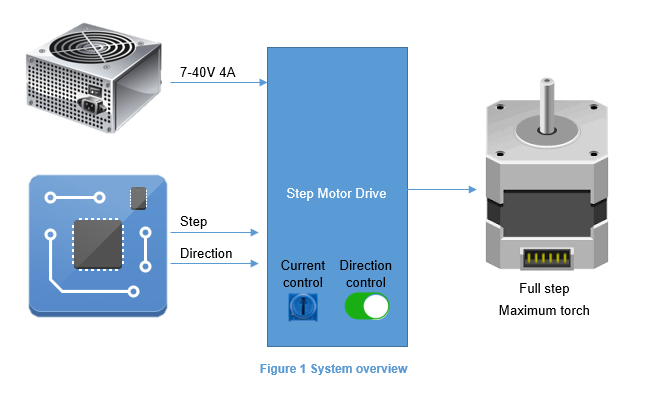
Blocks diagram
Considering I'm happy with it, I could create a small blocks diagram:
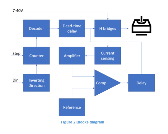
When I do the blocks diagram, usually I have in mind some components and try to track the number of ICs for different solutions, this is actually my favorite part. As I was using only CMOS logic, I use the wikipedia list of 4000 family, and the second place is the supplier (RS, digikey, mouser, etc), just to check the price among different compatible options.
Schematics
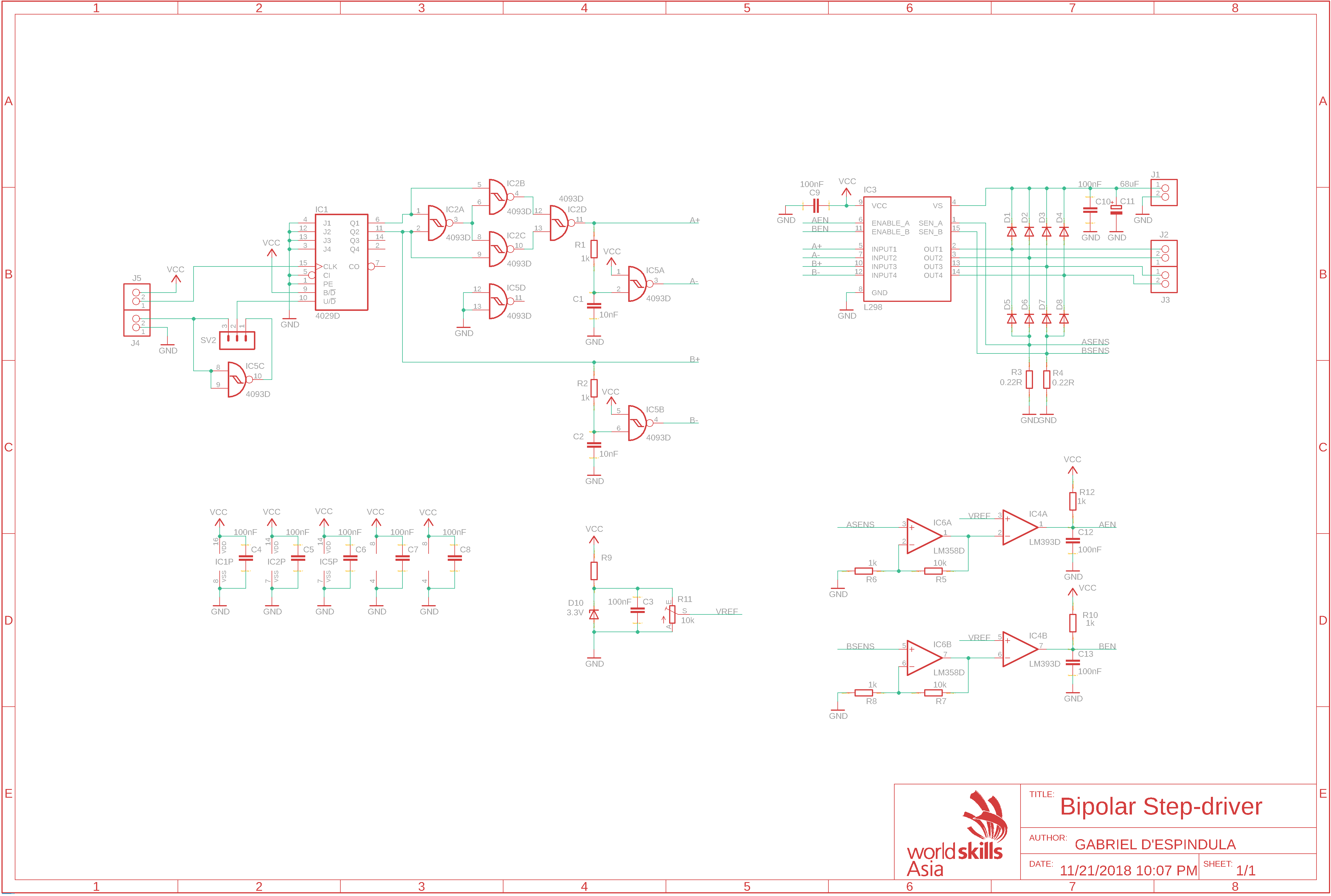
Turns out I came up with this circuit:
PCB
Finally, the board.
For this project, I've set some rules as following:
- Minimum clearance: 15mil;
- Minimum trace width: 15mil;
- Minimum via diameter: 1.27mm and 0,711mm hole;
- Board exact size: 95x75mm;
- 4mm holes on each corner. The centre of every hole is 5mm distant from the edges;
- The maximum number of jumpers is 30. More jumpers will deduce some points;
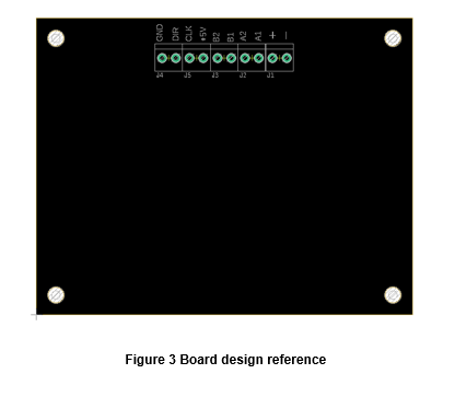
- The connectors must be attached together, aligned side by side, with a clear area between them and the board outline, to provide space for wires. Bellow there is an explicative illustration:
:D
 Gabriel D'Espindula
 Alex Muir
 ottoragam
 DIY GUY Chris