-
Nexion display: Understanding the Nexion code
08/29/2017 at 21:07 • 2 commentsMystery why the Nexion Arduino code only reacted on a button release is this:
The button press is triggered by this attach-Push command.
MotorEnable_Z.attachPush(MotorEnable_Callback, &MotorEnable_Z);The button release is triggered by this attach-Pop command.
MotorEnable_Z.attachPop(MotorEnable_Callback, &MotorEnable_Z);
I took some example code from Nexion and apparently used the Pop (=release button) only
I mistakenly confused it with a LIFO buffer. Push-Pop
Analyzing the Nexion protocol I also discover that it is not wise to use big names as buttons at the HMI implementation. When you request data from the HMI then it sends a big command to the Nexion slowing down the serial communication.
The Nexion Arduino implementation is actually very good code if you look at the sources, but I am probably going to start from scratch and squeeze out every bit of performance now that I understand the code.
The current implementation is a way to attach multiple callback events to a list. But one of my screens the number of buttons will be huge. I have a hunch that the MHI can support about 255 buttons per page.
void NexTouch::iterate(NexTouch **list, uint8_t pid, uint8_t cid, int32_t event)
{
    NexTouch *e = NULL;
    uint16_t i = 0;
    if (NULL == list)
    {
        return;
    }

    for(i = 0; (e = list[i]) != NULL; i++)
    {
        if (e->getObjPid() == pid && e->getObjCid() == cid)
        {
            e->printObjInfo();
            if (NEX_EVENT_PUSH == event)
            {
                e->push();
            }
            else if (NEX_EVENT_POP == event)
            {
                e->pop();
            }

            break;
        }
    }
}
Why would I need 255 buttons? Well imagine that you create touch zones ;-)
So how would I optimize such a thing?
I want one button on one page = only one callback for both button down and button up. This way I can flash jump to that callback instantly without a loop. The HMI sends very compact codes to the Arduino controller.
It is sad that a day does not have 72 hours, I really need more free time :-)
-
Using the Nextion display: Issue solved
08/27/2017 at 00:59 • 0 commentsFinally solved the issue with my Nextion display commands not being recognized by the Arduino Due code.
The Arduino implementation of the Nextion button and dual state button gets triggered when you release the button.
The button "press" command gets sent to the serial port but is ignored, you need the button "release" to be sent.
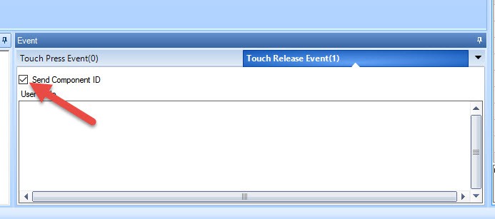
![]()
Make sure you activate this checkbox in order for the Ultratronics board Nextion implementation callback gets triggered. Without this the Nextion will not send the release event through the serial port.
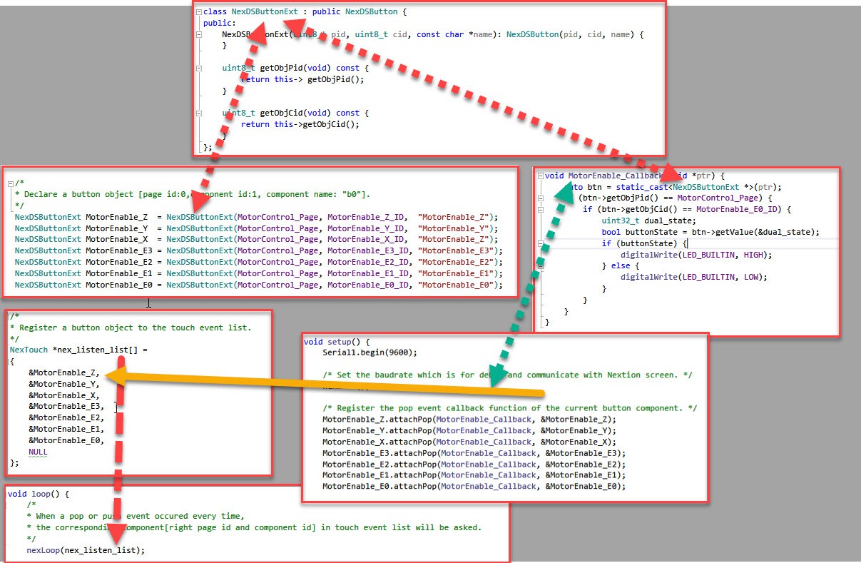
We need some code to extend the NextDSButton and the NextButton. Nextion decided to make the Pid, Cid and Name protected which is stupid since we can use this to make more compact code.
class NexDSButtonExt : public NexDSButton {
public:
	NexDSButtonExt(uint8_t pid, uint8_t cid, const char *name): NexDSButton(pid, cid, name) {
	}
	uint8_t getObjpid(void) {
		return this->getObjPid();
	}
	uint8_t getObjcid(void)  {
		return this->getObjCid();
	}
	const char *getObjname(void)  {
		return this->getObjName();
	}
};
class NexButtonExt : public NexButton {
public:
	NexButtonExt(uint8_t pid, uint8_t cid, const char *name) : NexButton(pid, cid, name) {
	}
	uint8_t getObjpid(void) {
		return this->getObjPid();
	}
	uint8_t getObjcid(void) {
		return this->getObjCid();
	}
	const char *getObjname(void) {
		return this->getObjName();
	}
};
So we start by exposing these protected fields (note C++ does not like that you use the same name, so I changed one character to lowercase for the time being).
This class will get extended a lot in the future as we develop the Thor functional code.
Using the extended classes is done with code below.NexButtonExt MotorEnable_E1_Left = NexButtonExt(MotorControl_Page, MotorEnable_E1_Left_ID, "b11");And finally can specifically choose the page number and the object and assign a custom action inside one method. No need for a separate callback for every button. Note the typecast to NextDSButtonExt.
void MotorEnable_Callback(void *ptr) {
	auto btn = (NexDSButtonExt *)(ptr);
	if (btn->getObjpid() == MotorControl_Page) {
		if (btn->getObjcid() == MotorEnable_E0_ID) {
			uint32_t dual_state;
			bool isValid= btn->getValue(&dual_state);
                        if (isValid) {
			    if (dual_state) {
			    	digitalWrite(LED_BUILTIN, HIGH);
        		    } else {
	        		digitalWrite(LED_BUILTIN, LOW);
	        	    }
                        }
		}
	}
}
void MotorEnable_Callback2(void *ptr) {
	auto btn = (NexButtonExt *)(ptr);
	btn->setText(btn->getObjname());
}
Example above changes the debug LED for a specific button on a specific page.
The second callback send the object name back to the button.
Time is up for this week. To be continued. -
Using the Nextion display: Hit a issue Part 2
08/21/2017 at 20:49 • 2 commentsThis weekend I hit an issue when I tested my Thor controller code in combination with my Nextion display that drives me nuts.
Because I have a 5V to 3.3V converter I hooked up the logic analyzer to see if I had issues with noise.
Conclusion: I do not have a signal noise issue.
![]()
I press the E0 button, the Nextion display sends a command to the Thor controller. Above is the 5V digital and in blue its 5V analog signal.
Lower the 3.3V digital and below that its analog signal.
Conclusion it is very clear that the Thor controller receives the signal and should trigger the callbacl function by sending back something. But nothing happens also the debug LED does not pop up.
A second test with a different button makes me confused.
![]()
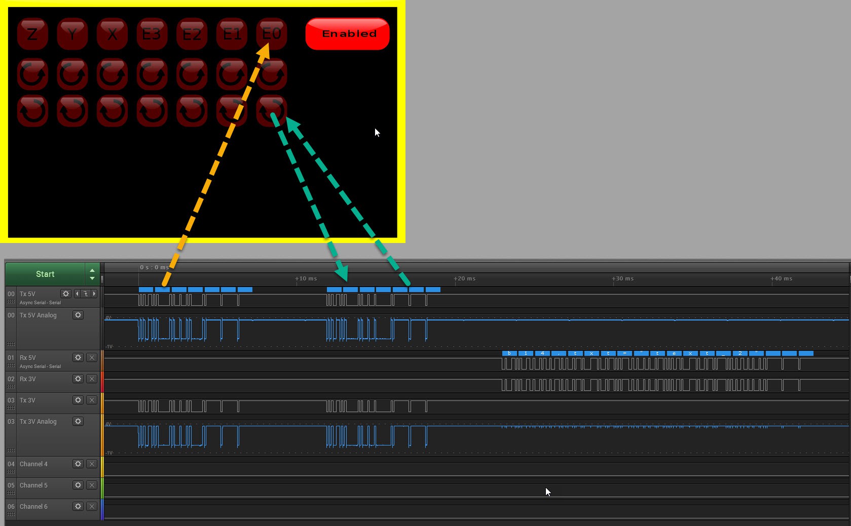
I press the rotation buttons 2 buttons below the E0 (digital signal in the middle. You clearly see the Thor controller responding. But what is weird is what is in front of it. That is the button down press of the E0 button I did not press.
When I test them on the other rotate buttons I never get this E0, E1, E2.... in front of it what is different?
The transmitted test text to see if the callback gets triggered seems to be clear text: 'b14.txt="text_2"' in the logic analyzer output.
-
Using the Nextion display: Hit a issue
08/20/2017 at 12:35 • 0 commentsWhen developing the Arduino code I appear to have an issue when I use the Dual-State button.
![]()
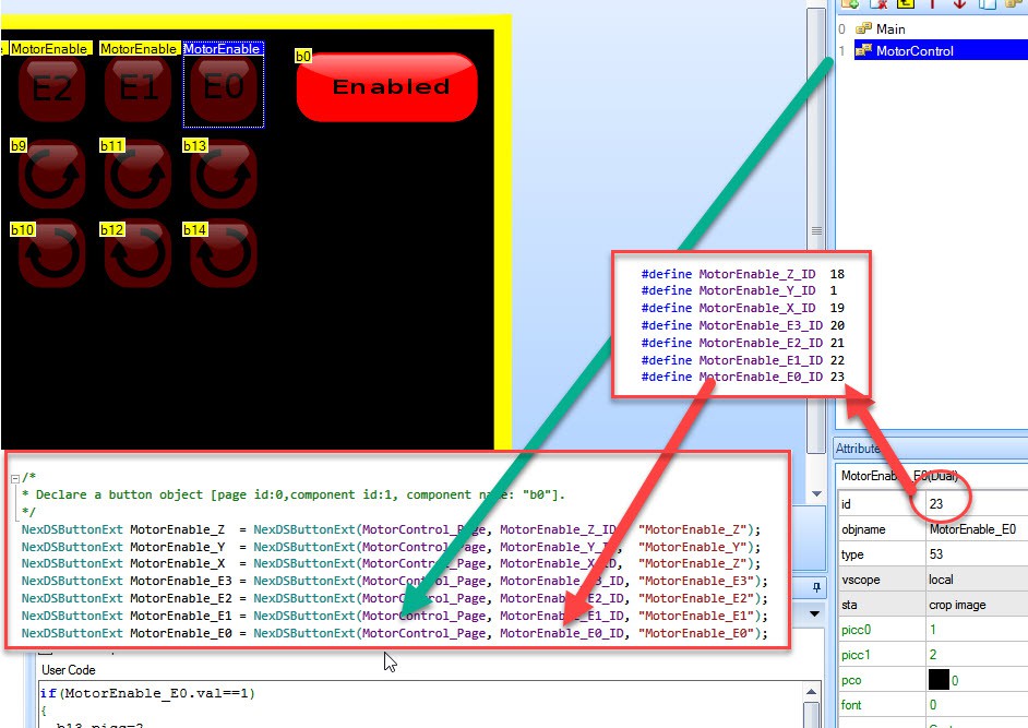
As far as I have learned, in the Arduino I need to instantiate an object from class NexSDButton with the the page number and object ID per button. (The description is important when you send commands to the Nextion display)
So I created some constants for the pages and the buttons to define them. I do not seem to be able to change the ID once I created the button in the Nextion editor.
(The NexSDButtonExt will be explained later)
![]()
The implementation of NexSDButton hides the pageID (pid) and the ComponentID (cid). I need that access because I want to have only one call-back. Not 100's of call backs for every
By inheriting from NexSDButton I extend the class NexSDButtonExt and expose the methods: getObjPid() and getObjCid()
My call-back can now be simplified. Code above shows for MotorControl_Page and MotorEnable_E0_ID I will activate the debug LED when the state = 1 and shut off the debug LED when state=0
Only it does not work. I see no state change at the Thor part.
(The code works perfectly inside the Nextion HMI processor)
![]()
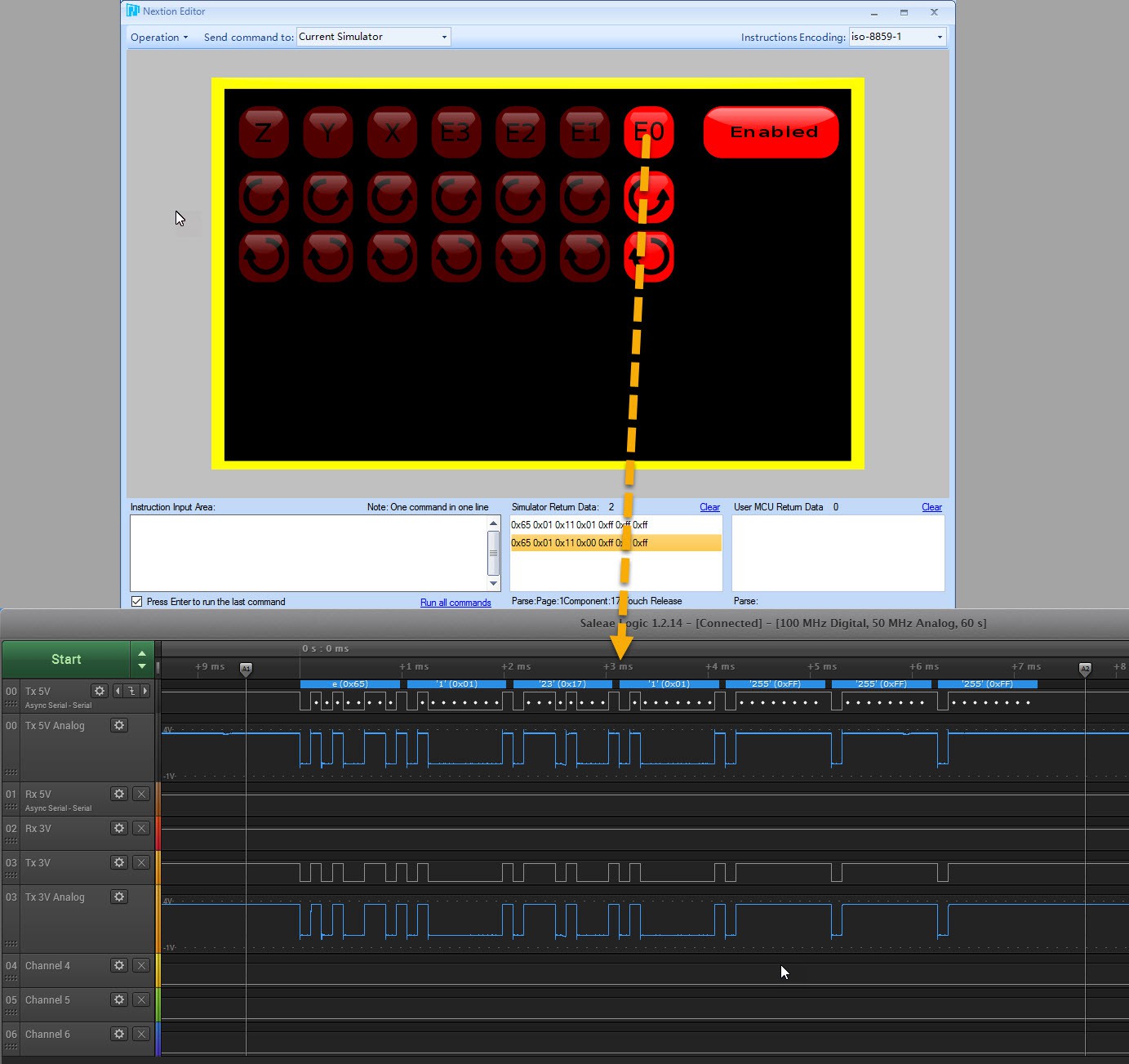
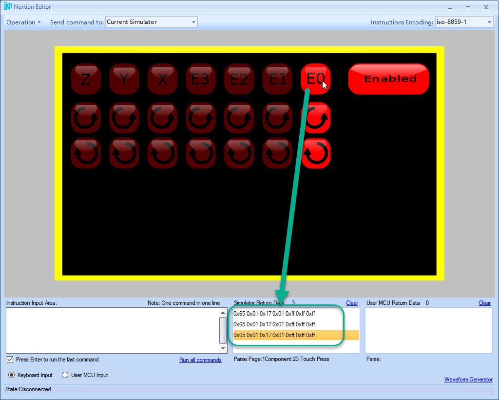
Going to the debug screen in the Nextion editor I can see what commands are being send to the Thor controller. You recognize the second byte as page 1 and the third byte the component ID in hex. The components state which is "1" and always "1" when I click the button on or off. I think this is the reason why I only see a "1" state at the Thor controller side. (Incorrect!)
UPDATE: I checked the code on the Nextion forums and it appears that this is normal. 0x65 is marked as "button click" event. The second 0x01 means "button pressed" and 0x00 means "button released".
The example code I found to get the value (bool buttonState = btn->getValue(&dual_state) ), seems to send a second request to the Nextion display for that particular value. Then it should return with it. For some reason the value never returns.
![]()
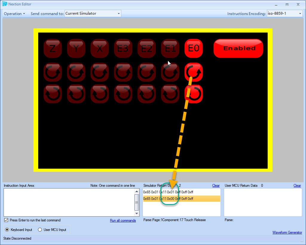
Compare it with a normal button and here you do see the state change.
I may have to revert to a simple button, or maybe use a "variable". Whatever the solution is, I want the number of transmissions between the controller and the Nextion HMI as low as possible. A good solution no quick hack.
-
Tiny status report: Images
08/15/2017 at 14:16 • 2 commentsLast time I reported that the 7 Inch Nextion display draws a lot of current that the Ultrasonics v1.1 board could not deliver. What you see is the display flash brightly then gets dark then boots, flashes brightly then dark in an endless repeating loop. It is constantly rebooting because it lacks enough power.
The original power source I used for 5V was the one on the power supply itself but that meant that parts of the board still gets power when I cut off the 24V switch to emergency stop the motors.
A double pole connector could have been used. One to cut the 5V and on to cut the 24V but I preferred a different approach.
![]()
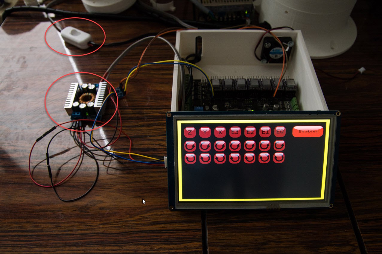
So I ended up with a buck converter that is now feeding from the 24V line and has enough power to deliver 5V for the Nextion display and future sensors or additional controllers. And can also act as a source to make 3.3V It reduces the number of wires outside the controller.
As you have noted this controller box is too small for the 7 Inch Nextion display.
![]()
Here is an example how the screen is in action.
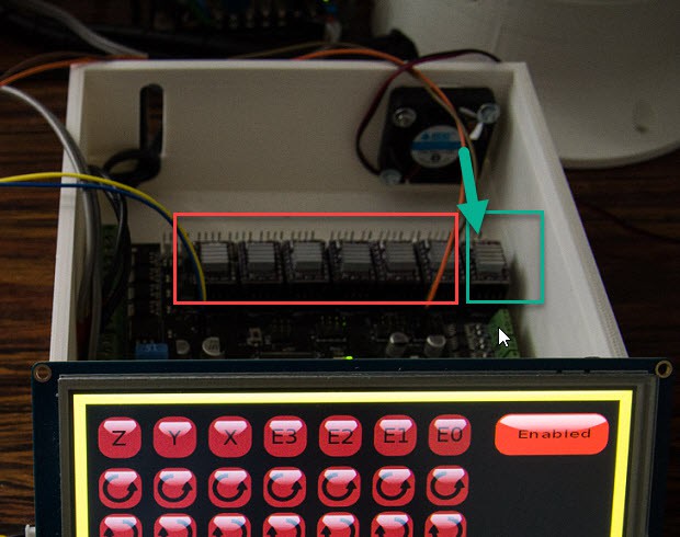
I used the order of the Polu drivers from left to right: Z, Y, X, E3, E2, E1 and E0
![]() E0 is intended for the main base motor. This one draws the most current and heats up the most. The fan is directly blowing air on it. The idea is to also include the 24B to 5V buck converter into the box.
E0 is intended for the main base motor. This one draws the most current and heats up the most. The fan is directly blowing air on it. The idea is to also include the 24B to 5V buck converter into the box. ![]() Because I ordered a 300W Buck converter it turns out bigger than expected. Tests showed that it stayed cool when I tested it on the Nextion display for an hour. So I decided to buy a 100W version that would be smaller.
Because I ordered a 300W Buck converter it turns out bigger than expected. Tests showed that it stayed cool when I tested it on the Nextion display for an hour. So I decided to buy a 100W version that would be smaller. And the big surprise came it looked exactly like the 300W version, identical components too. So I think that my 300W version is fake and can only support 100W..
![]()
One last tip. Unlike Danny I am not going to go for a slip ring. I want to be challenged to adapt my software that it also has to take into account the limitations of the movement.
To prevent my cables to get caught into the cog mechanism I wrapped them up into a wrapper.
Originally I had all my cables into one cable wrapper, but when I had to demontage the parts I lost a lot of time to unwrap the cables in order to remove the top part. So I learned to use 2 different cable wrappings. One the goes to the base only, then one that goes to the upper part. And I maybe use one for the upper arm too.
Every stepper motor has 4 wires. This way I can find back what motor group is connected to what connector during the assembly and testing easily.
As I develop my software, I need a way to only test certain parts of the robots while the rest are disconnected. Disconnected means that they cannot do you any harm when I have a programming bug.
-
Nextion display: First steps
08/15/2017 at 01:58 • 2 commentsFor the Thor robot I need a debug display. A display with the sole purpose of controlling every single stepper motor independent or together.
But the first step is learn to program the Nextion display.
The whole intention is to make this UI ready for a industrial production environment in the end. The end-goal of this project is to scale it well.
So here we go... in pictures. The graphics are not artistically perfect yet.
![]()
The power on/off button is deceivingly complex to find a good solution. We are not dealing with a simple alarm clock but a machine that can kill its owner. ;-)
It is not the bitmap itself that is complex but the way to design the UI where safety is taken into account, use the UI elements wisely and none confusing for the operator.
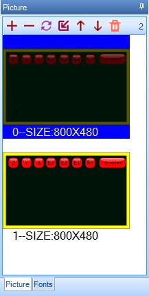
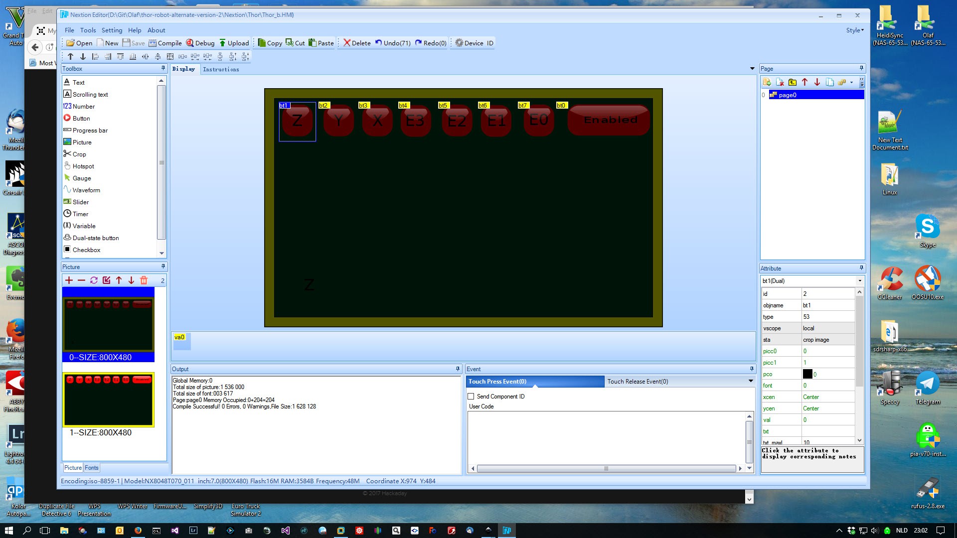
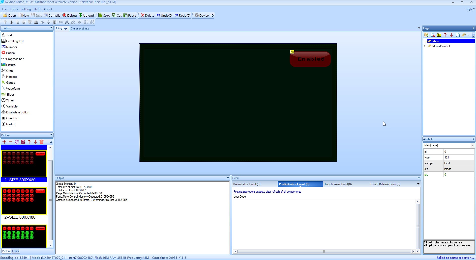
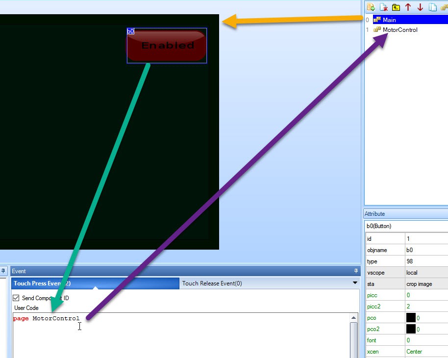
When the robot powers up I want a display that shows only one button that is in a disabled state.This becomes my main screen.
![]() A second page is now added specific for motor control and when the button gets pressed the "MotorControl" page is loaded. That one has a active power button.
A second page is now added specific for motor control and when the button gets pressed the "MotorControl" page is loaded. That one has a active power button. ![]()
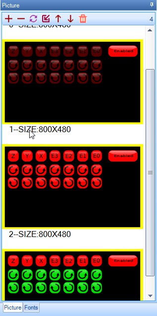
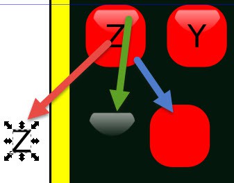
I loaded 3 different bitmaps. "1", "2" and "3" (=green buttons)
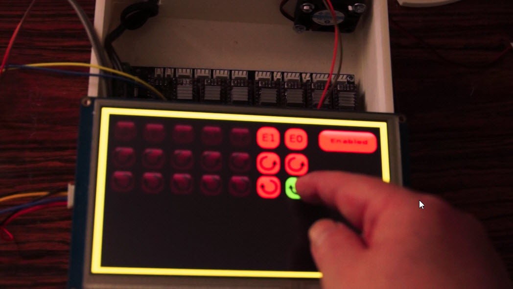
The intention is this. When I press the upper button, the rotating symbols for the 2 buttons below should lid up in red indicating that they are active and dangerous when you press it.
And when you actually press the rotating button then it should change color. In my case I have chosen green. I want a clear indication that the display actually responds to your button press. Whe you release it then it turns active red again.
![]()
The upper buttons that enables the 2 rotating buttons in its row is chosen to be a dual state button. We use the Crop Image function so it crops the bitmap of the chosen layer onto the display
The dual state button means that it stays pressed when release it and have to press it again to get depressed.
The rotating buttons are normal buttons so they get depressed when you stop pressing.
![]()
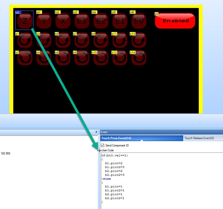
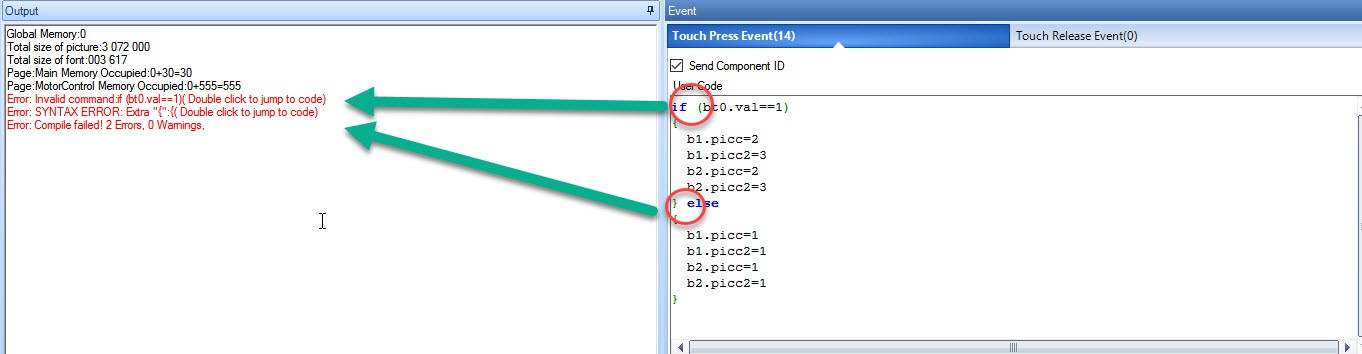
The code to execute when the dual state button gets pressed or depressed.
This code means that if the button is pressed, it will modify b1 and b2 deselcted state to layer 2 and selected state to layer 3 bitmap.
If not pressed then both the selected and deselected state are set to the same disable bitmap. I don't want to see it changing color when you press that region.
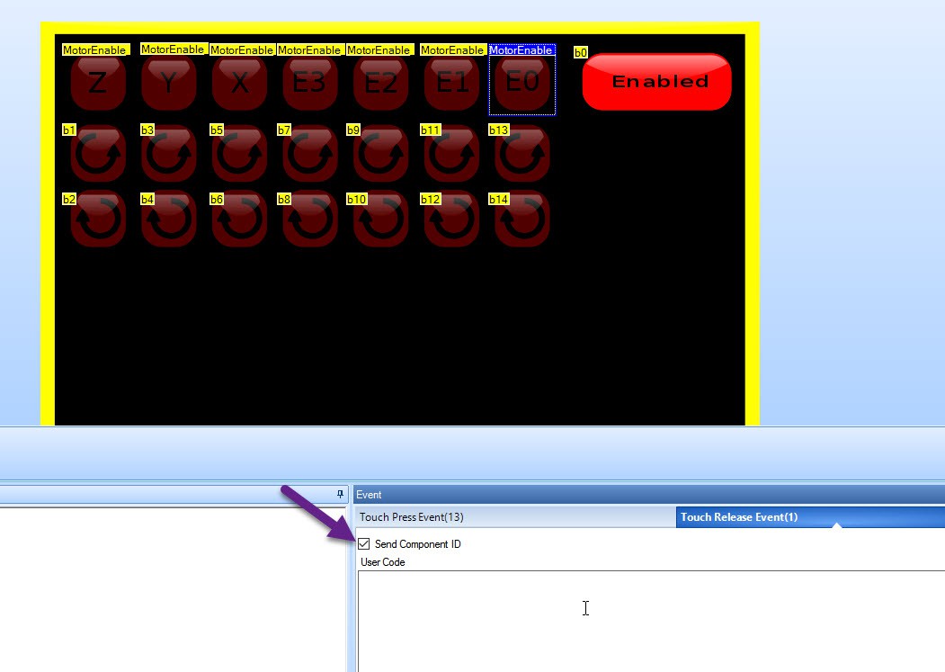
I also tried this code in the Touch Release Event, but then the changing buttons have a slow update. In the Touch Press event it reacts instantly.
Note: The "Send Component ID" is the command to send the event towards the Arduino. If you deselect this then no command is send and the Arduino is not aware.
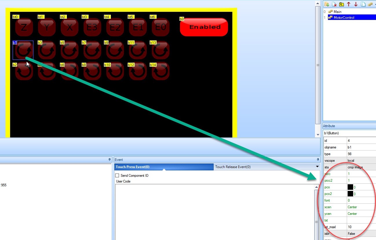
![]()
The Nextion display online help is not very helpful inn figuring out how to program it but the clue is i the property panel. Green properties fields seem to be modifiable through programming.
![]()
Warning, the Nextion editor appears to be beta. I had trouble understanding why I got this error and it turned out to be a simple spacing. remove it and it compiles. This is clearly an editor bug.
![]()
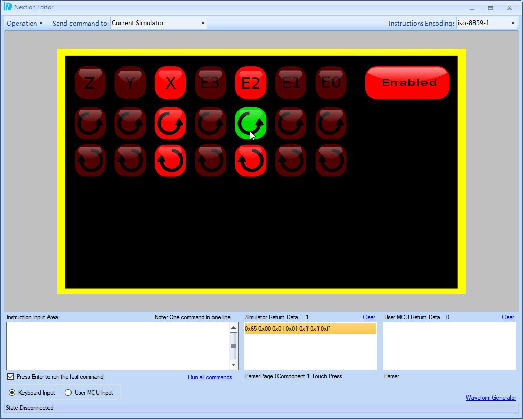
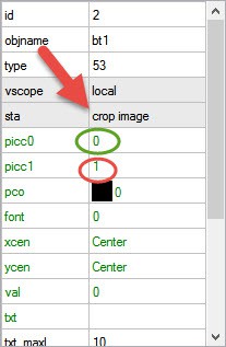
The final end-result to demonstrate how it should operate.
The green button is a pressed button, but it only changes green when the top button is active.
The top button will be hooked to the motor enable/disable. This controls if the motor is active or not.
The rotating arrow gives the direction how the motor will rotate and the duration will be the number of steps you execute by timer.
Note that the rotation does not represent the rotation of the Thor robot but of the motor direction only. The intention of this screen is to calibrate the motor and determine if they move in the correct direction in a testbed before assembly. You don't want the newly assembled robot to turn in the wrong direction caused by a wrongly connected connector.
This step will become vital when you develop your mathematics to control this robot. If you are 100% sure that the motor is connected correctly then the only conclusion will be that you math has a "-" when it needed a "+".
-
Controlling the Robot: The power on/off button
08/11/2017 at 19:05 • 0 commentsPowering on/off such a silly thing but in the world of robotics nothing is that simple!
I originally had a 2 bitmaps, one with all buttons off and one with all buttons on. Then I figured out that the ON button should always be lid because it wants your attention that you can hit that button to power it on. So I changed the background to all buttons off except that one. The fact that other buttons gets lid up (and I have a yellow warning border) is an indication that the power is really on.
I toyed with the idea to change the power button green when it is off and red when it is on, but in the end that is not a good idea because the power on or off is always a dangerous button. You don't want to power a robot off when it is busy doing something. So this one will always be red.
Also powering off is not that simple. A sequence of safety commands must be executed before the screen loses control. The robot must go to the nearest safety point before it can power off.
These safety points and actions must be known BEFORE the robot starts any motion. It must know before because when an emergency happens the robot has no time to start calculating. It should act as soon as possible just before the powers goes out.
Imagine a robot with a blowtorch. When you hit the power off button then you want the robot to turn that torch away from your target. The circuit that turns off that blowtorch may fail or never get the turn off signal because it is on a separate circuit. But the robot has control over its motions and move the torch away as a second fail safe mechanism
I realize that this Thor project is not that dangerous, but the whole point in building one is to learn stuff like this would be a big giant industrial robot. Safety must be part of the design. -
Multiple buttons on the Nextion display
07/29/2017 at 21:27 • 0 commentsI developed the buttons in Inkscape to be used for my Thor project.
I am still in my "Learning Inkscape" phase, it is a big learning curve to become a button graphics designer :-) But basically the button consists of 3 parts. The back color, the text and the reflection.
![]()
The button background is a flat solid color. This and the reflection is a gray gradient that uses transparency. This way it makes it very easy do duplicate the buttons and change the color or the enabled/disabled state.
We create 2 different background in Inkscape, one with all buttons disabled and one where all buttons are enabled.
![]()
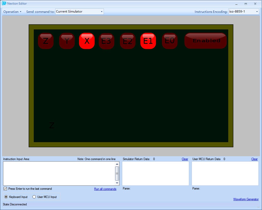
In the Nextion editor load the 2 different backgrounds.
![]()
Now we add the buttons on top of the background. To make them transparent,we select the button, go to properties and select "crop image"
![]()
We get now 2 items that select the pressed and the unpressed button state. picc0 is the depressed button image data source, picc1 is the pressed button image data source.
![]()
The debug view now show that we can individually select a working on./off state of thee buttons.
This way we can get more complex graphical elements that may not be square at all.
-
Programming the Nextion 7" panel
07/01/2017 at 21:04 • 1 commentFor the Thor robot I use the Ultratronics v1.0 pro board which is basically an Arduino Due.
The touch panel that I want to use is the Nextion 7" HMI panel.
These are the steps that I had to take to make the panel work with the Ultratronics board.
![]()
The panel layout is develop with the Nextion editor. Then compiled, put on a micro SD card and inserted on the display. Power off-on and it gets loaded into flash. Remove the micro SD card and power off and on then the display is active.
The graphical layout depends on your graphical skills.
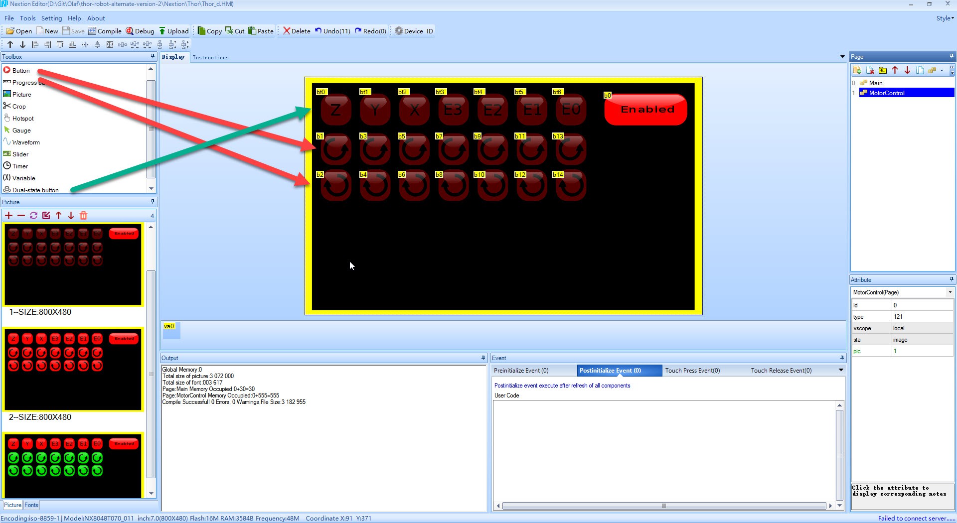
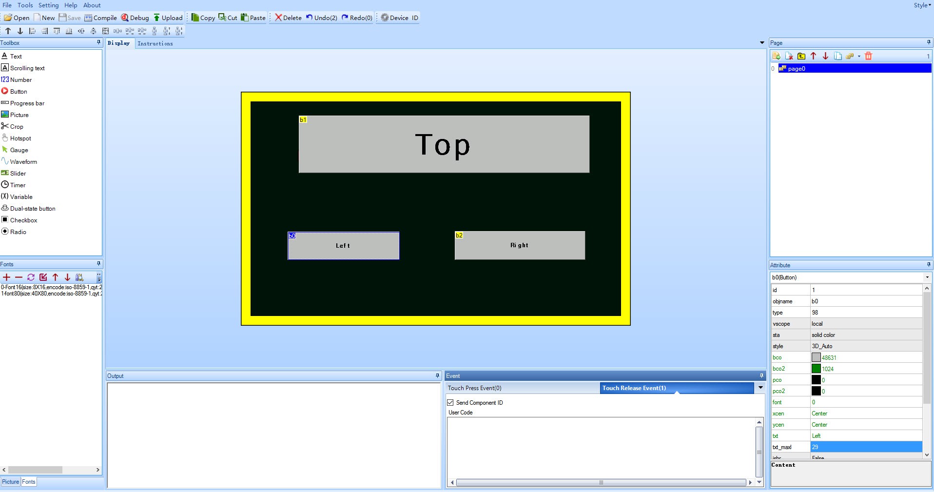
![]()
Important to that we have these buttons marked as b0, b1 and b2. This will come back in our Arduino programming.
![]()
Also make sure that for every button you have activated a event when the button gets released. Thsi event is then transmitted through the serial TxD and received by the Arduino.
Get the software for the Nextion found here: https://github.com/itead/ITEADLIB_Arduino_Nextion
Then copy it to the location of your Arduino libraries or your local project.
The Ultratronics is an Arduino Due, and this code is not compatible for the Arduino Due simply because SoftwareSerial.h does not exist for the Due. It took some time to find what I had to do with it.
We need to do 2 modifications
![]()
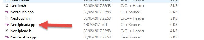
So open file NexUpload.cpp
![]()
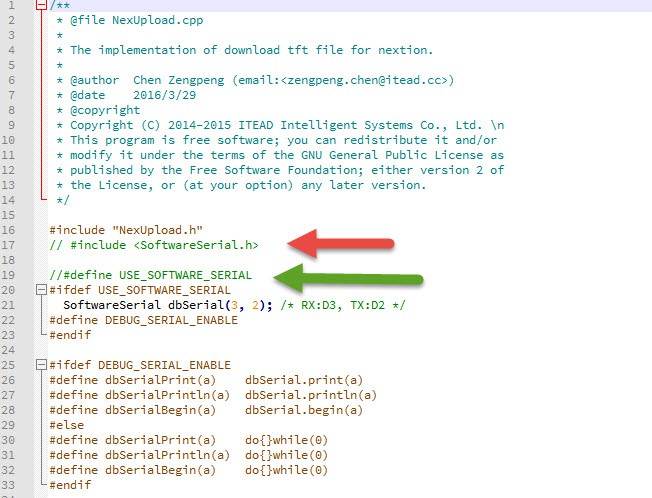
Now comment out the #include SoftwareSerial.h, since this prevents you to compile for the Arduino Due.
And since we will use one of the additiopnal UART's let's comment out the USE_SOFTWARE_SERIAL.
![]()
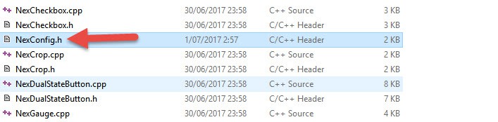
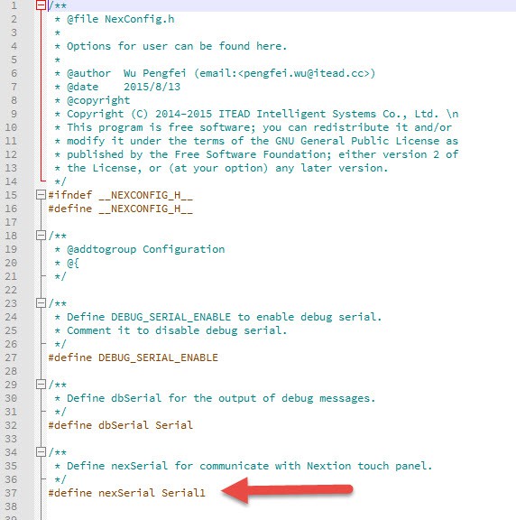
Next step we will define what UART we will use so open NexConfig.h
As described in my previous log I have hooked it to Serial1. (note the "1"). Also note that Serial (without the number should maybe defined as Serial0)![]()
Now how do we use it?
In your Arduino project
#include "Nextion.h"

/*
* Declare a button object [page id:0,component id:1, component name: "b0"].
*/
NexButton b0 = NexButton(0, 1, "b0");
NexButton b1 = NexButton(0, 2, "b1");
NexButton b2 = NexButton(0, 3, "b2");

char buffer[100] = { 0 };

/*
* Register a button object to the touch event list.
*/
NexTouch *nex_listen_list[] =
{
	&b0,
	&b1,
	&b2,
	NULL
};

/*
* Button component pop callback function.
* In this example,the button's text value will plus one every time when it is released.
*/
void b0PopCallback(void *ptr)
{
	uint16_t len;
	uint16_t number;
	NexButton *btn = (NexButton *)ptr;
	memset(buffer, 0, sizeof(buffer));

	/* Get the text value of button component [the value is string type]. */
	btn->getText(buffer, sizeof(buffer));

	number = atoi(buffer);
	number += 1;

	memset(buffer, 0, sizeof(buffer));
	itoa(number, buffer, 10);

	/* Set the text value of button component [the value is string type]. */
	btn->setText(buffer);
}
Notice in the project b0, b1 and b2 defined as in the Nextion editor.
This code actually increments and send the number to that button. On your Nextion display you get the incremented number on that button every time you press it.
void setup() {
	Serial1.begin(9600);

	/* Set the baudrate which is for debug and communicate with Nextion screen. */
	nexInit();

	/* Register the pop event callback function of the current button component. */
	b0.attachPop(b0PopCallback, &b0);
	b1.attachPop(b1PopCallback, &b1);
	b2.attachPop(b2PopCallback, &b2);
        ...
}
We attach the defined buttons and callback to execute for each button.
void loop() {
	/*
	* When a pop or push event occured every time,
	* the corresponding component[right page id and component id] in touch event list will be asked.
	*/
	nexLoop(nex_listen_list);

}
And finally the loop that searches for events and call the callback function.
This screen is not intended for streaming video, the fact that the HMI takes all the processing power makes he serial communication actually pretty efficient and low on CPU cycles on the Arduino.
-
Connecting the Nextion 7" panel
07/01/2017 at 19:14 • 0 commentsThe Nextion 7" HMI panel is a self contained processor that drives the display independent of what is connected to it. The displays, button, interactions are configured using a micro SD card.
It has a bidirectional serial communication protocol Rx/Tx to tell the connected controller what button is pressed and the connected controller can then send data back that can be used to display.
![]()
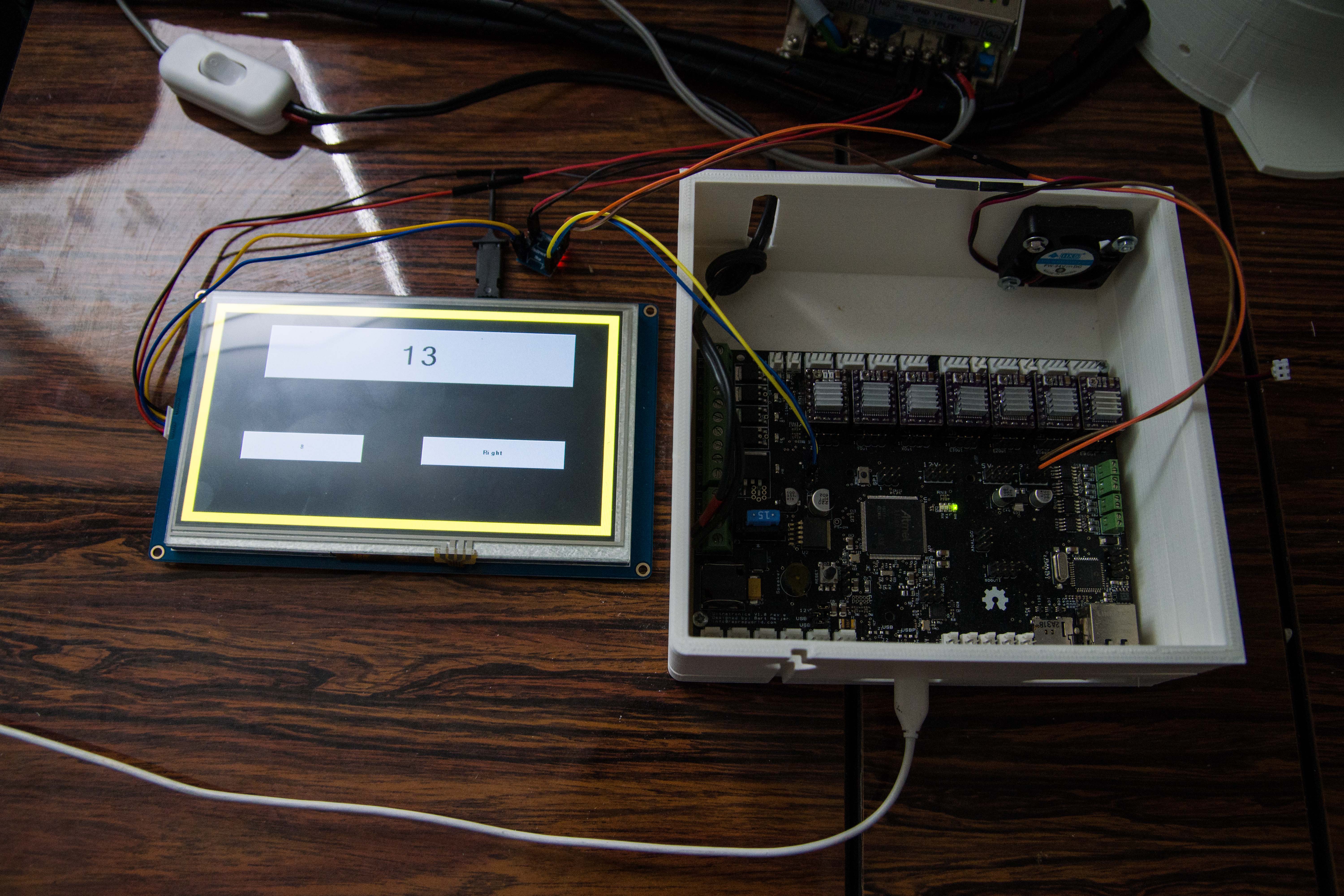
Left is the Nextion 7" HMI display with 3 buttons programmed on it.
Right is the Thor controller (Ultrasonics v1.0 pro), which is basically an Arduino Due.
This Ultratronics v1.0 pro board does provide 5V and 3.3V power but this 7" draws way too much current so I had to connect the 5V to my 5V power output directly.
The power switch you see above top left is connected to the 24V. Early experiments turned out that the main power source I use is a but too powerful and when I pull the 220V power, it still has enough power to drive stepper-motors for a few seconds. I did not want to lose fingers during these few seconds so that is why this 24V cut of switch is there.
(In the future I want an internal 24V to 5V step down inside the box. so I only have to draw from the 24V main power supply.)
![]()
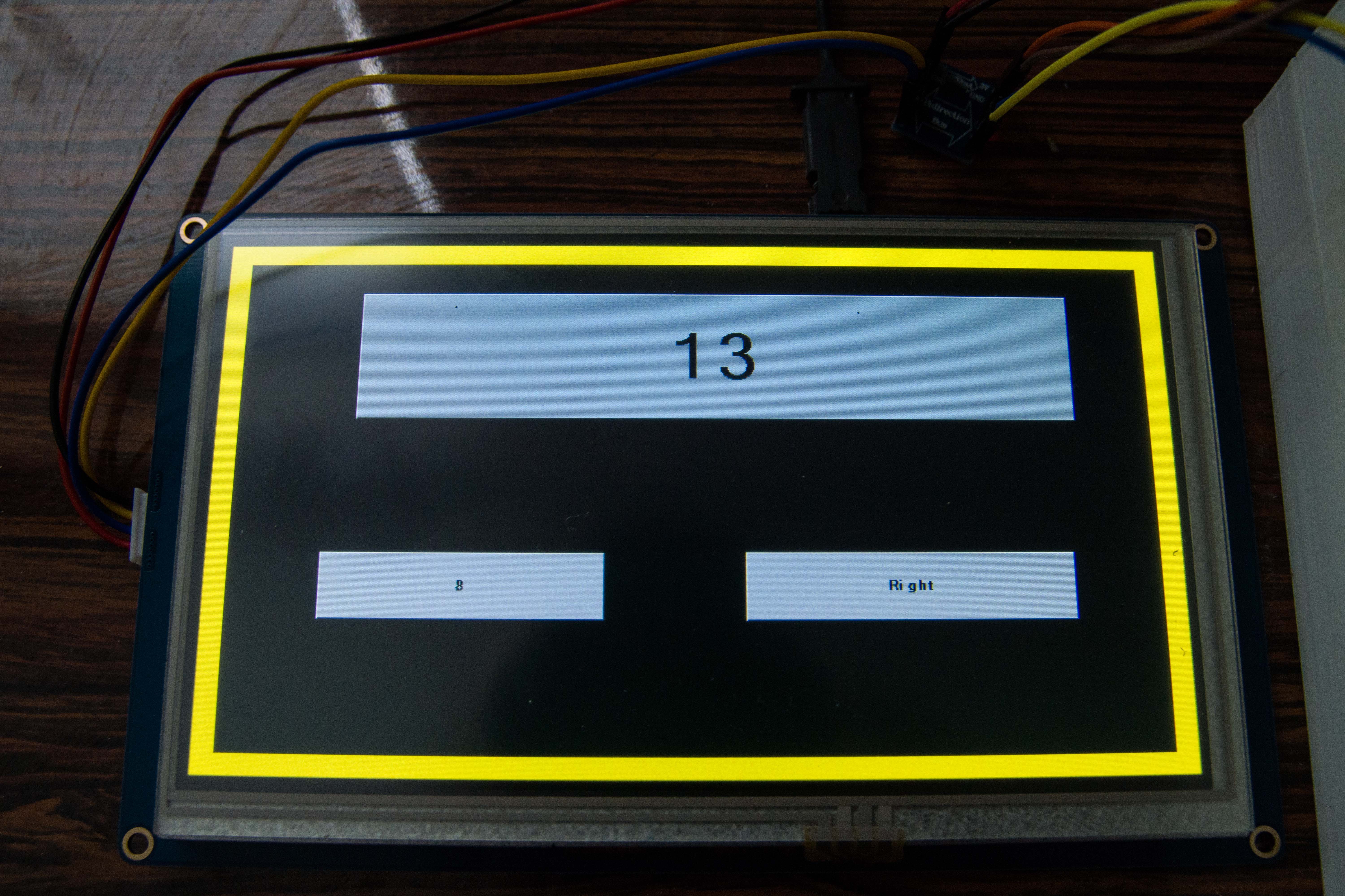
The Nextion display with test buttons.
The numbers you see here is the number of times I pressed the button, a command was sent to the Thor controller. The Thor controller incremented a number and send it back to be displayed. This is just a test-setup to verify the complete loop.
![]()
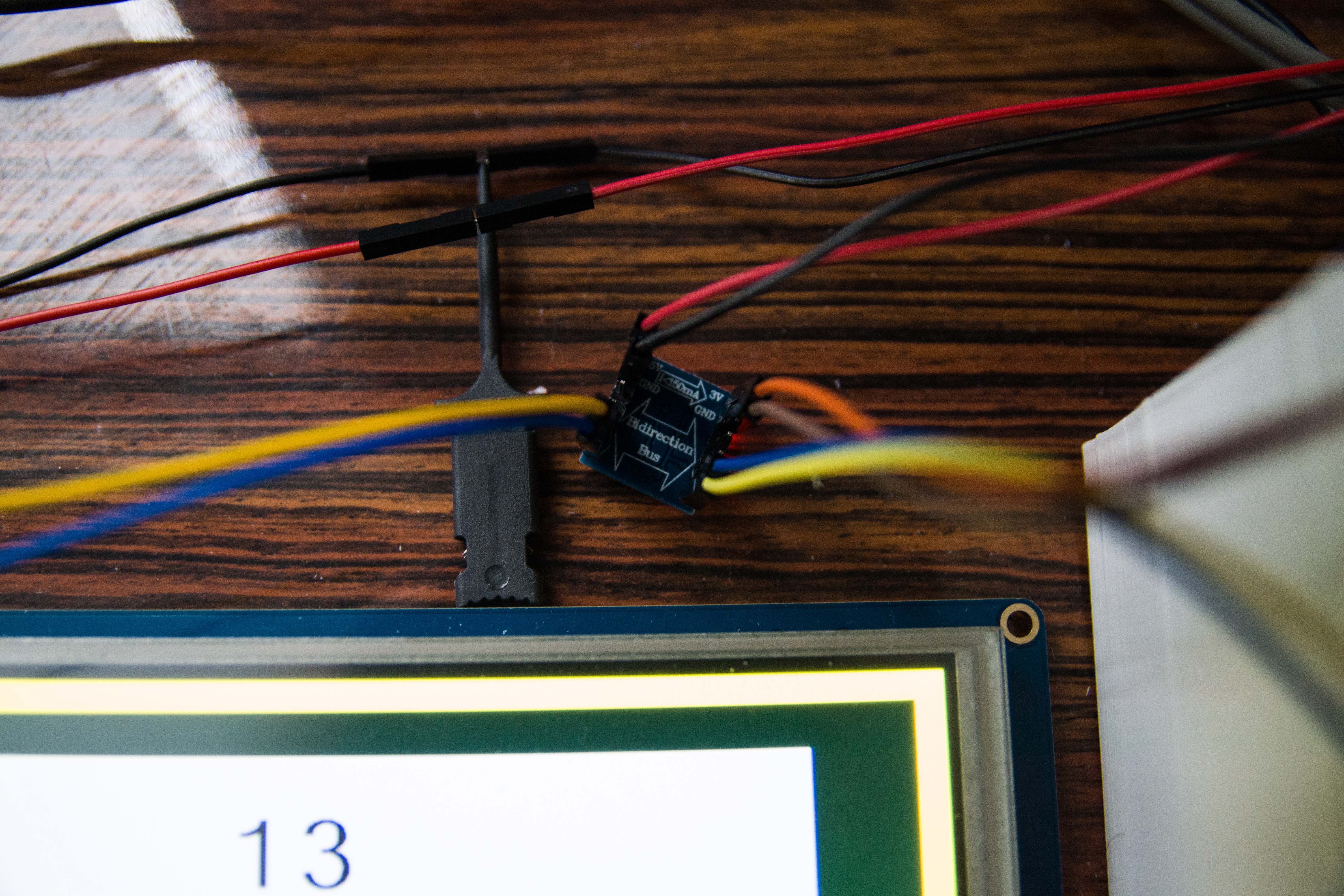
The Nextion displays operates on 5V. The Ultratronics v1.0 pro board runs at 3.3V. So I need a bi-directional level shifter that is able to step up,/down the Rx/TX signals.
Note that here we swap the RX to TX and the TX to Rx.
![]()
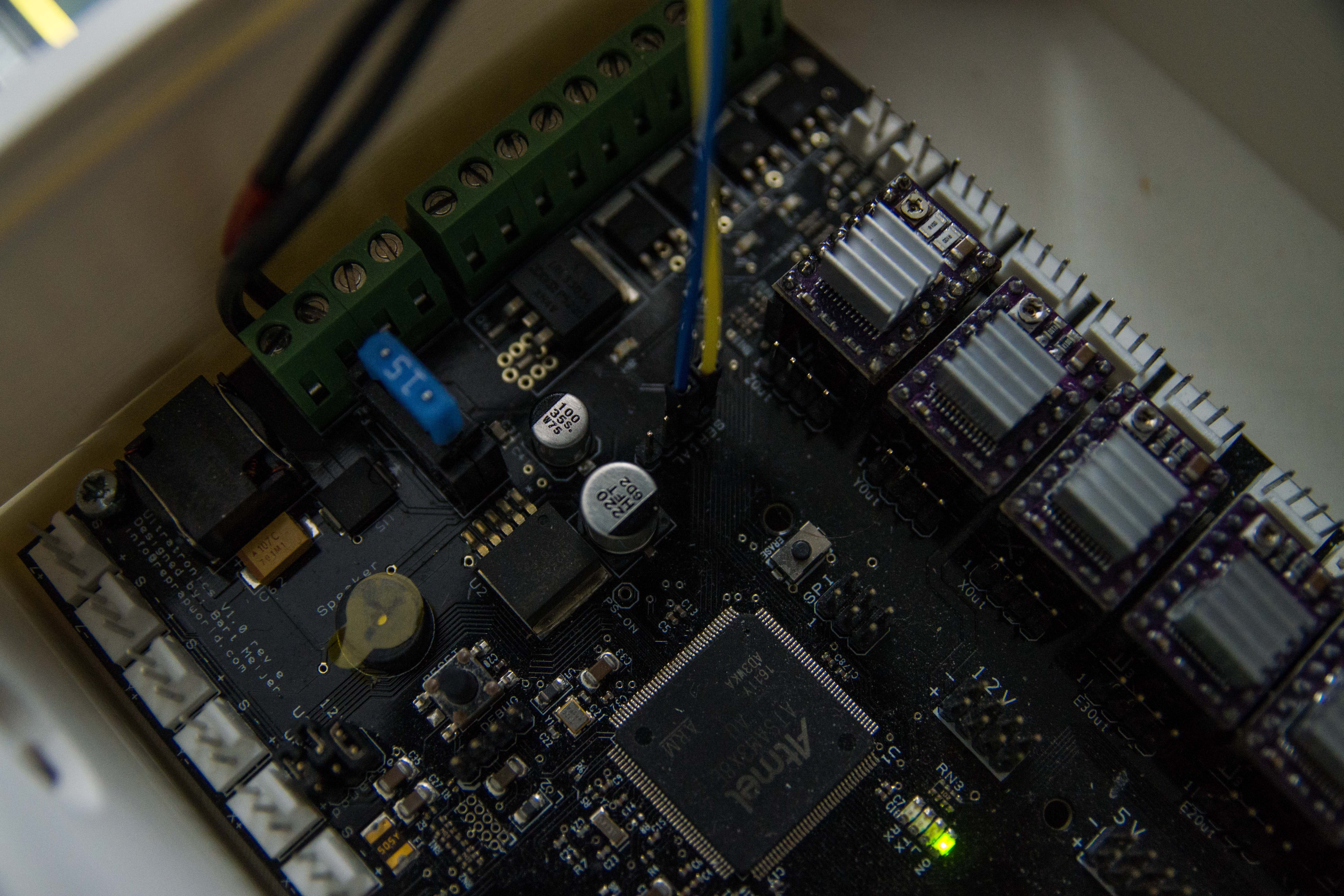
The Ultratronics v1.0 pro board has more than one UART and this one is using Serial1 (Don't confuse this with Serial without the number)
I want to point out that the Ultratronics board documentation is wrong or, the pin 1 assignment on the board is in the wrong place.
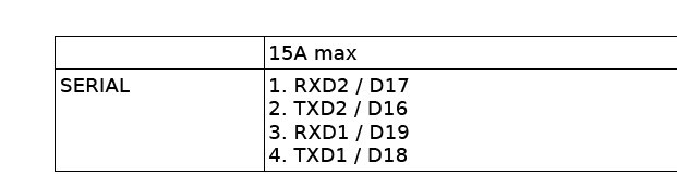
This is what the documentation tells me.
It took some time to figure this out but pin 1 is actually TXD1, pin 2 is actually RXD1 on the motherboard.![]()
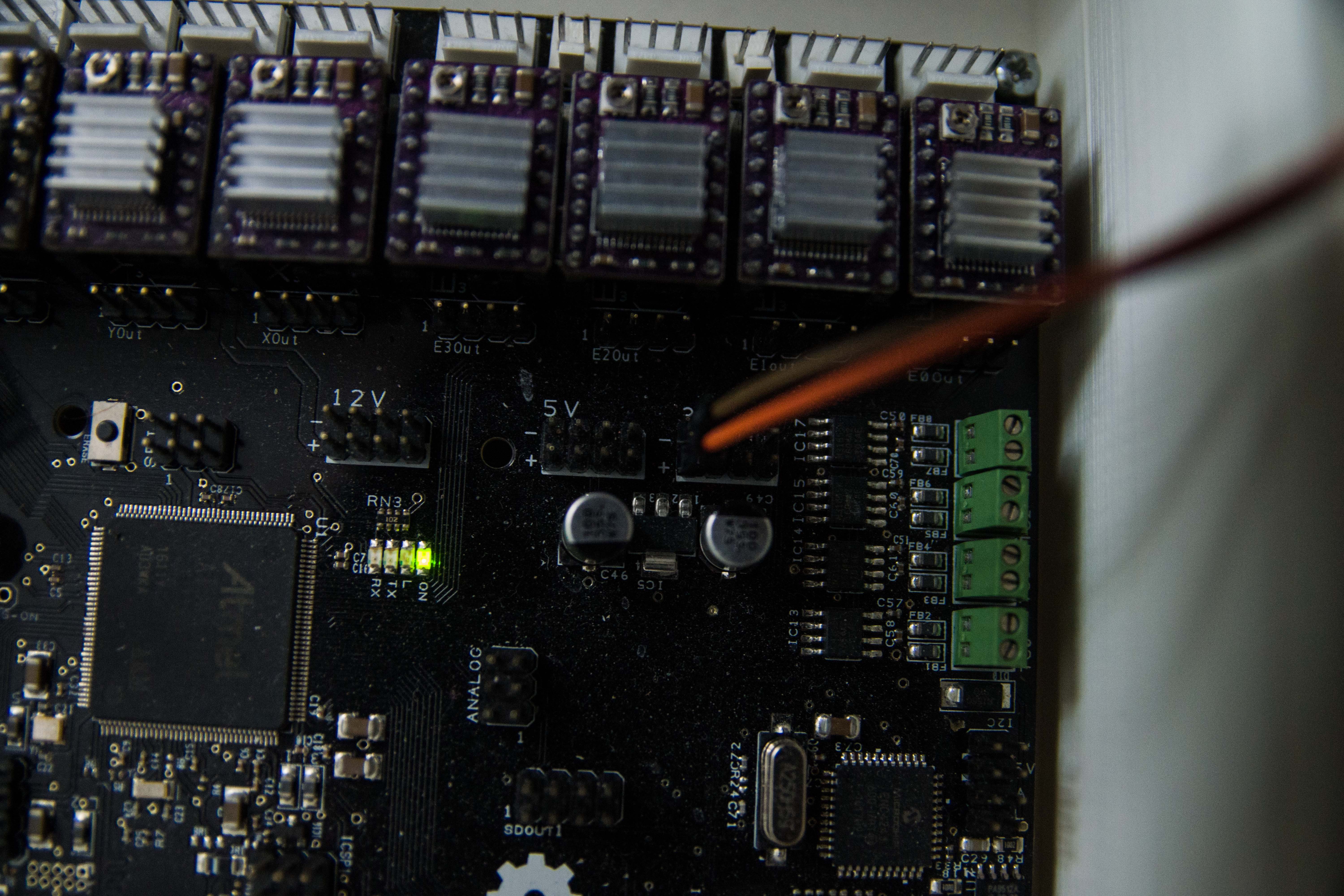
![]()
I drew the 3.3V for the bi-directional level shifter directly from the main board. The 5V was not enough to power the Nextion display.
Also note that the minus of the 3.3v is at the upper position. I accidentally connected it wrongly and I saw smoke coming out from my level shifter.
Building the Thor robot
Building a 6-axis robot based on the Thor robot. When size DOES matter!
 E0 is intended for the main base motor. This one draws the most current and heats up the most. The fan is directly blowing air on it. The idea is to also include the 24B to 5V buck converter into the box.
 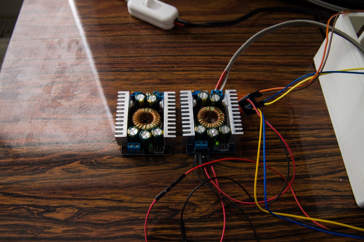 Because I ordered a 300W Buck converter it turns out bigger than expected. Tests showed that it stayed cool when I tested it on the Nextion display for an hour. So I decided to buy a 100W version that would be smaller.
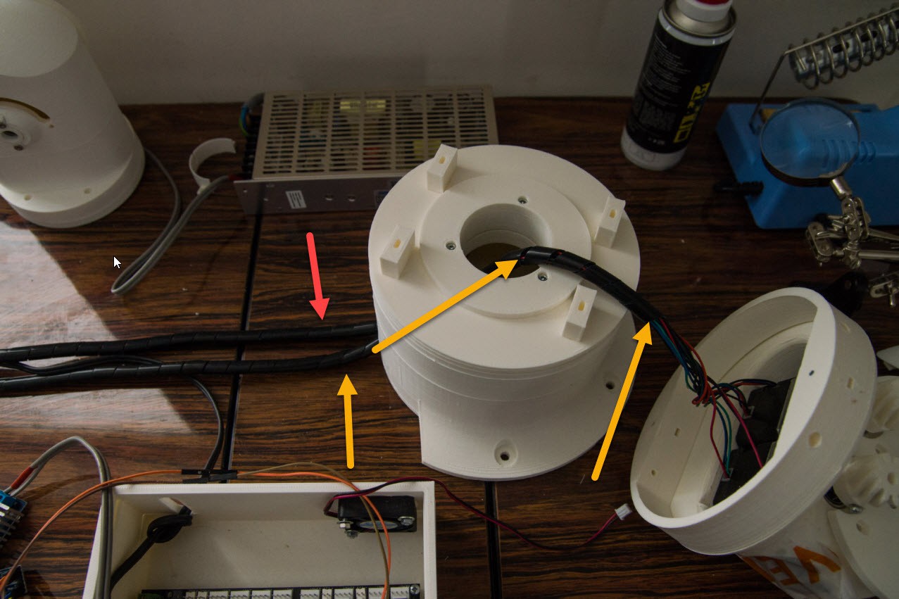
 A second page is now added specific for motor control and when the button gets pressed the "MotorControl" page is loaded. That one has a active power button.