-
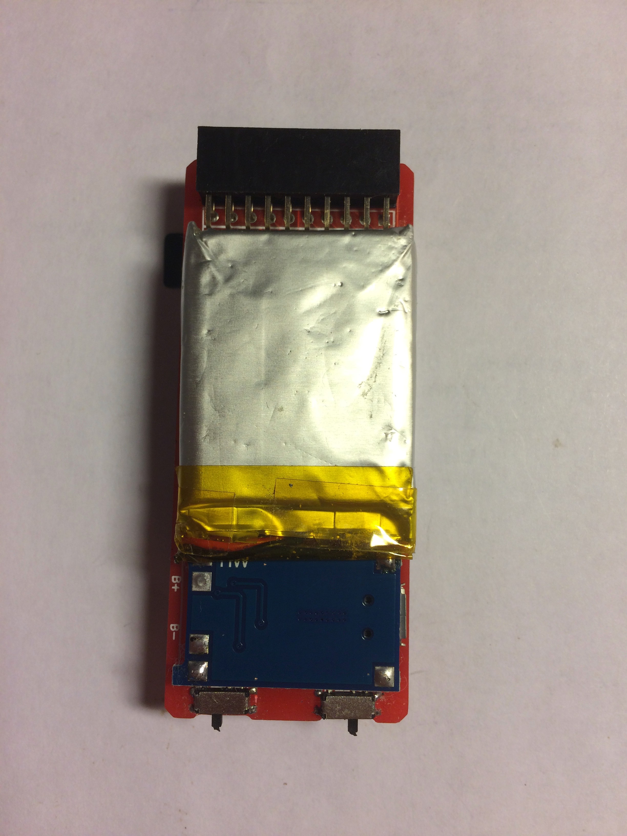
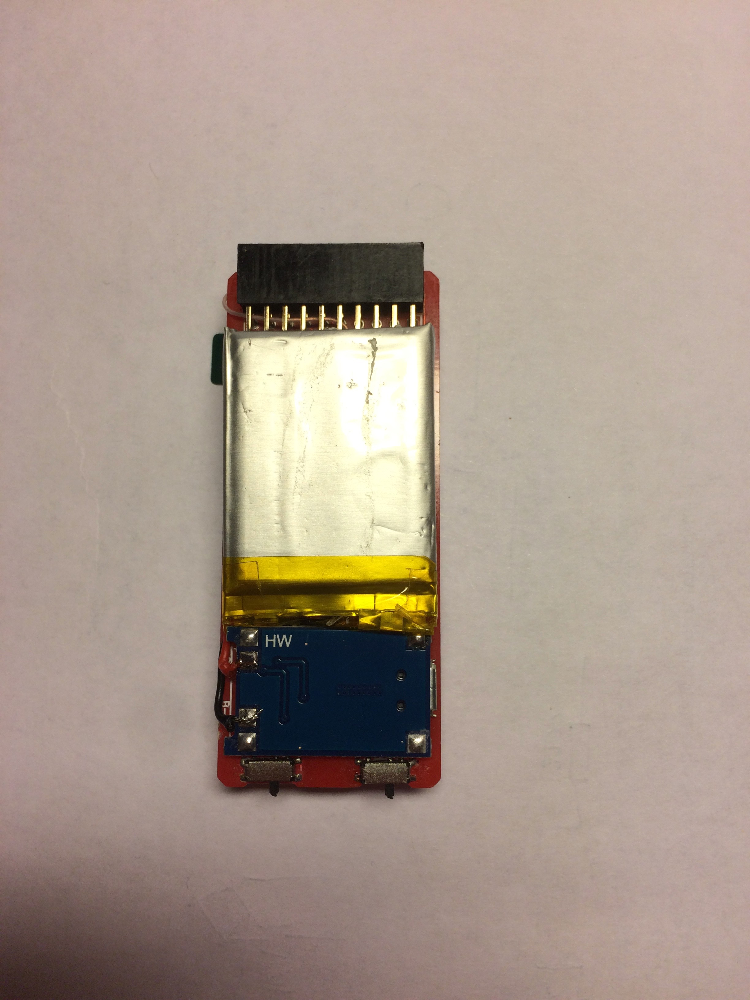
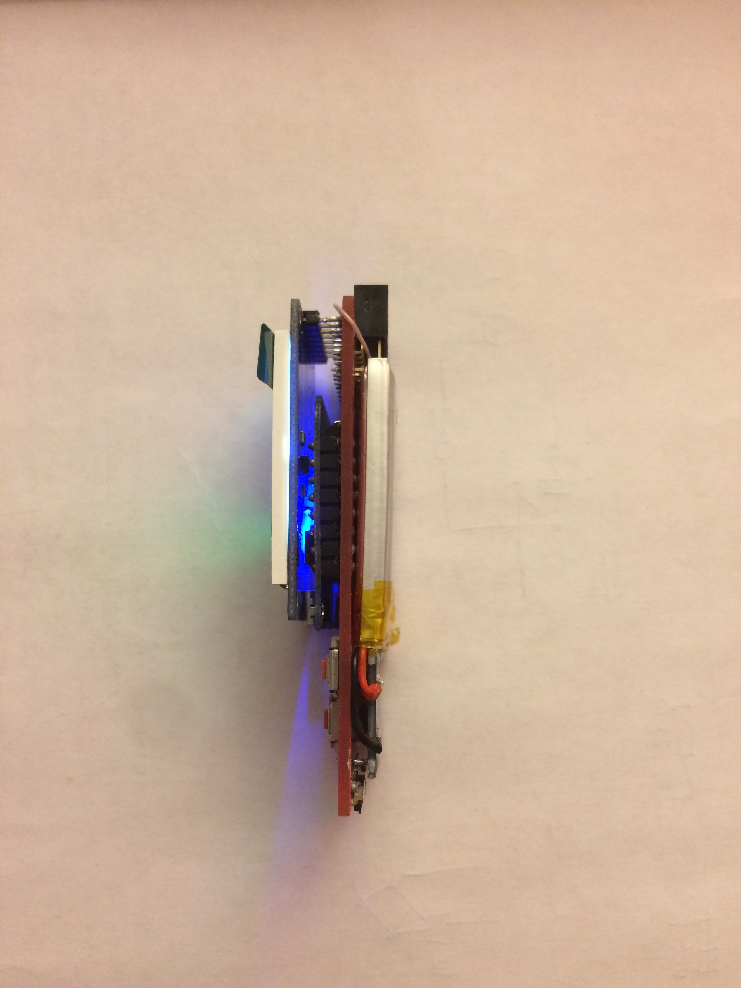
11Solder and set battery to B+ and B- of TP4056 charging controller
Be careful!
B+ is for RED battery wire
B- is for BLACK battery wire
![]()
![]()
-
12Congratulation! Mission complete ) Have fun!
Adjust sound volume by variable resistor at the bottom of the PCB between two side switches.
It's easy to ajust the volume runing the "Sound test" program in LGE package or playing any other sound or music. Avoid too load adjustment due to minor distortions and vibrations.
Remember that there are TWO USB connectors. The one at the side-bottom is only for charging the battery! You can not use it for updating the firmware of microcontroller.
Another one is on microcontroller module for updating the firmware, you can not charge the battery with it.
![]()
![]()
ESPboy - RetroGaming&Software development MuliTool
For IT geeks, retro game fans, makers. Open source, portable, modular to explore, create, learn, code & play
 RomanS


Discussions
Become a Hackaday.io Member
Create an account to leave a comment. Already have an account? Log In.