-
1Check the video build instruction
-
2ESPboy Kit and parts
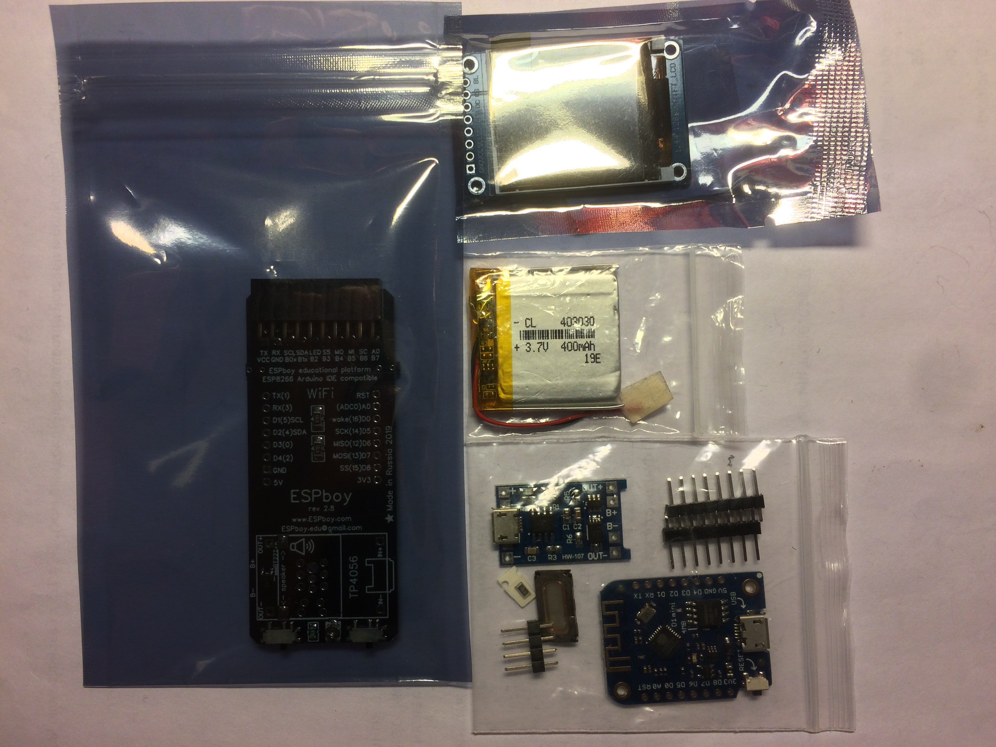
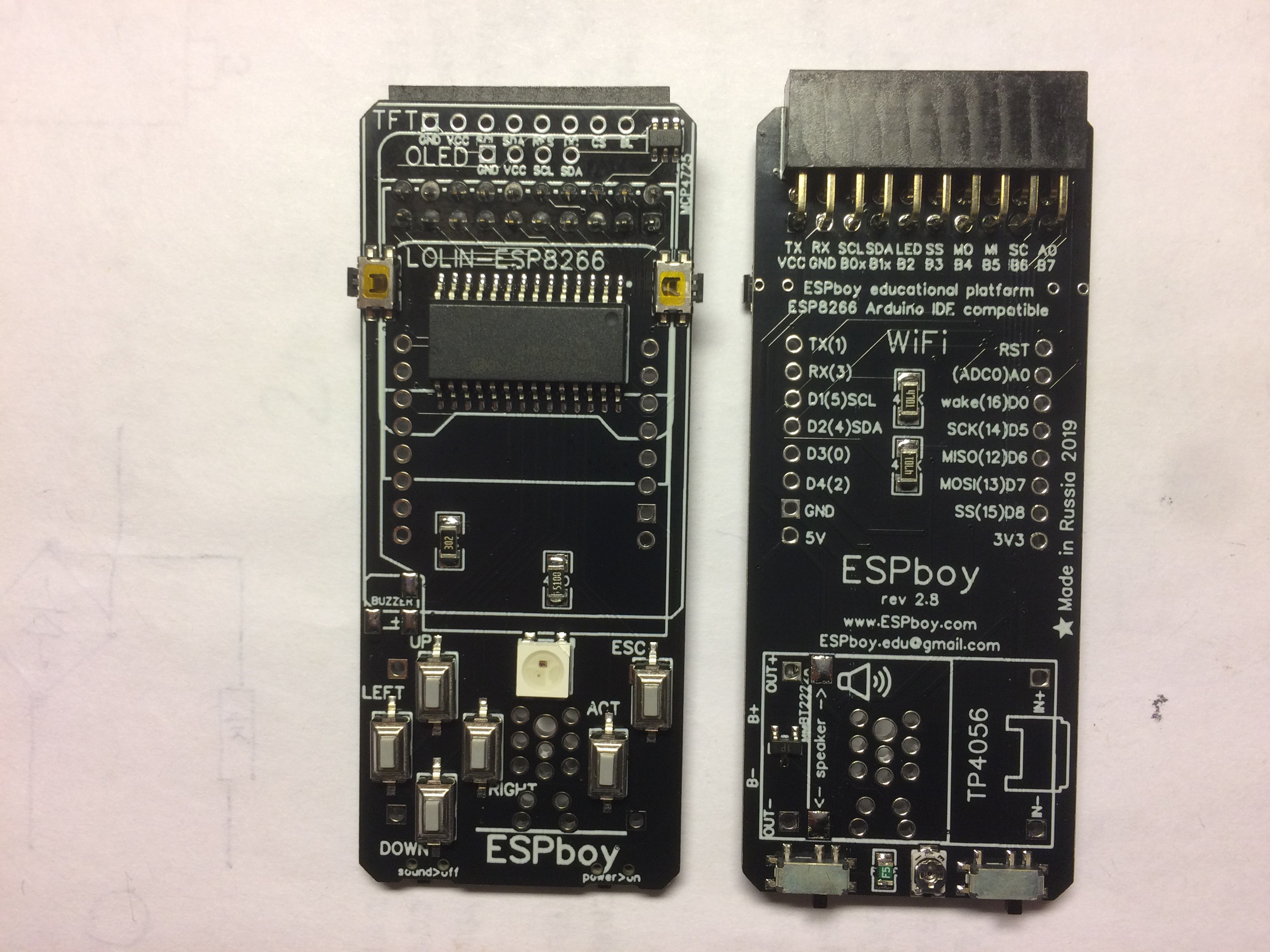
You can get ESPboy Kit with partially preassembled PCB where is soldered most of small components.
Only 3 modules and speaker should be soldered in following order:
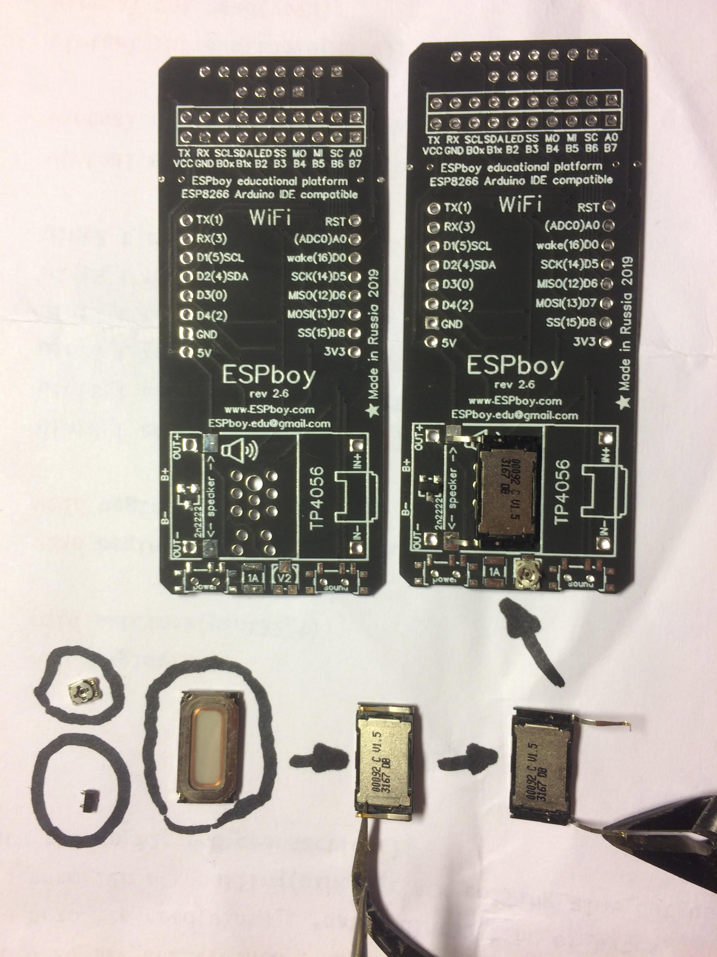
1. speaker (as you can see on black PCB pictures, not buzzer, as at red PCB pictures)
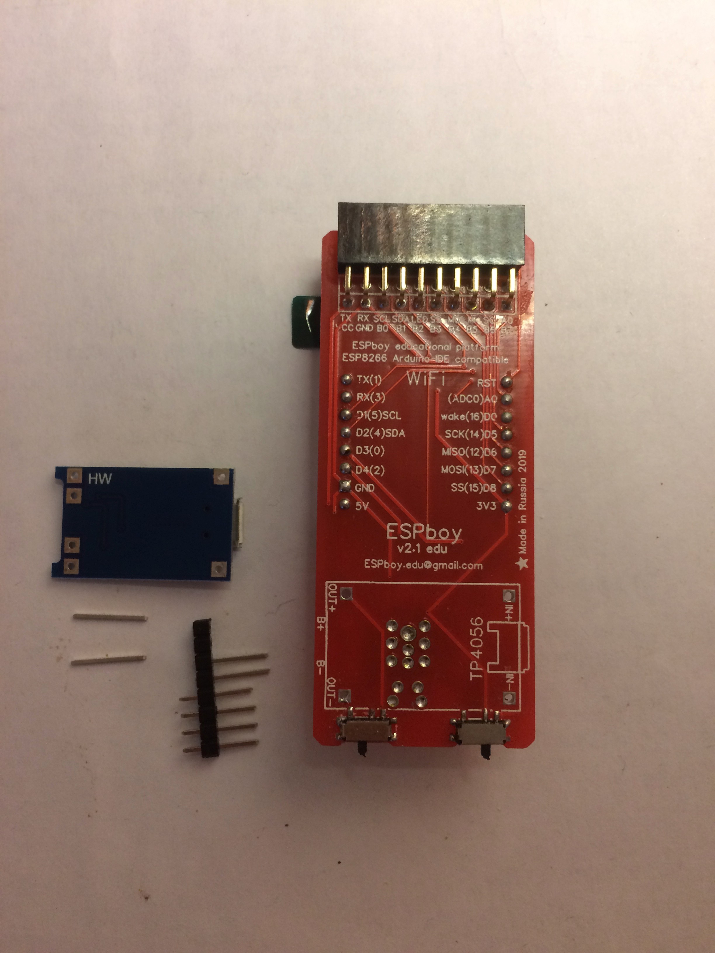
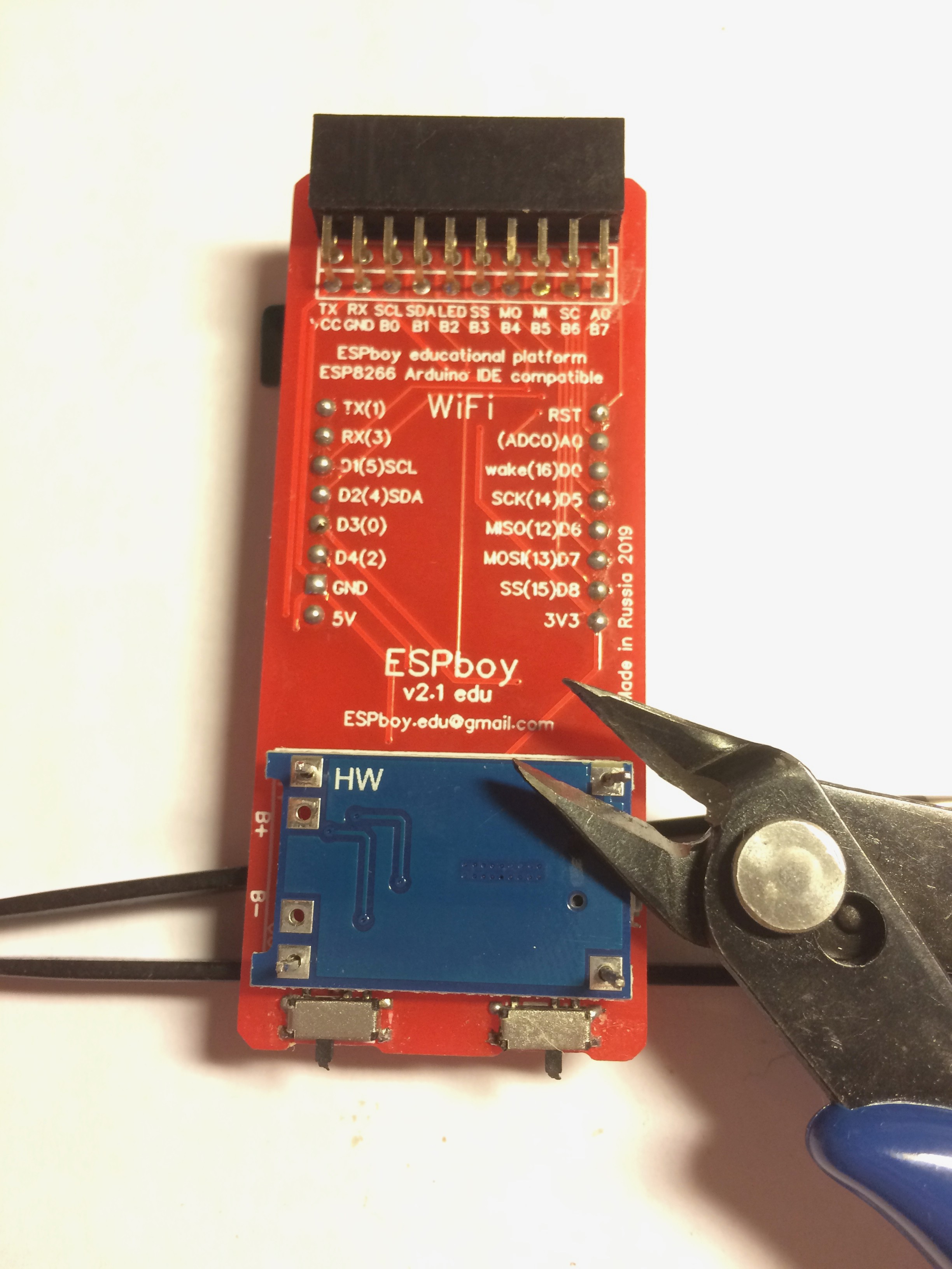
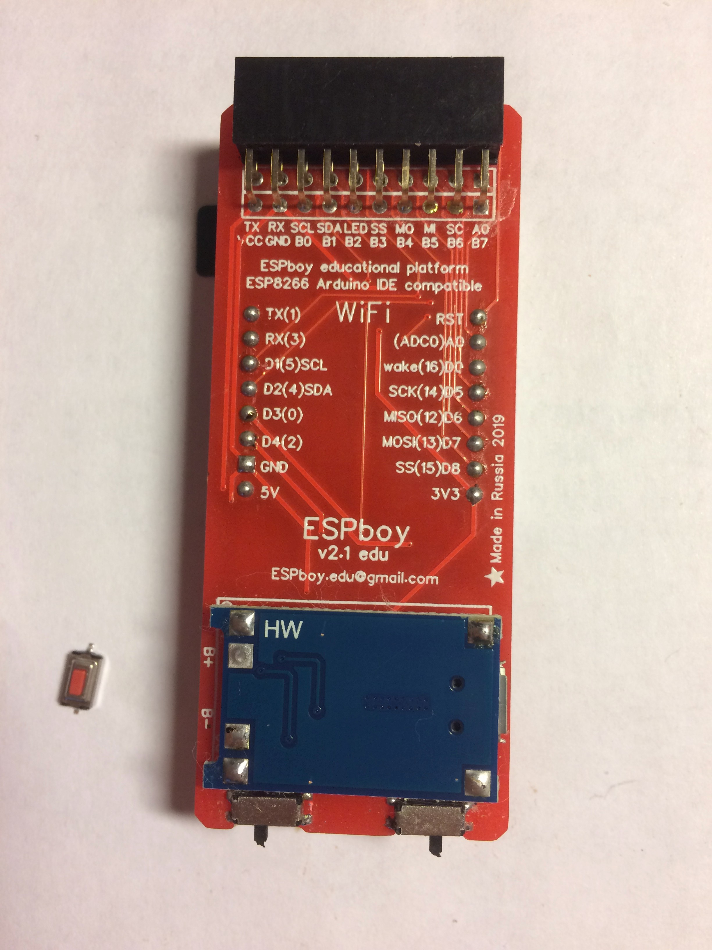
2. TP4056 battery charging module (don't forget to replace R3 resistor according the following info)
3. WeMos D1 mini (LOLIN) microcontroller module
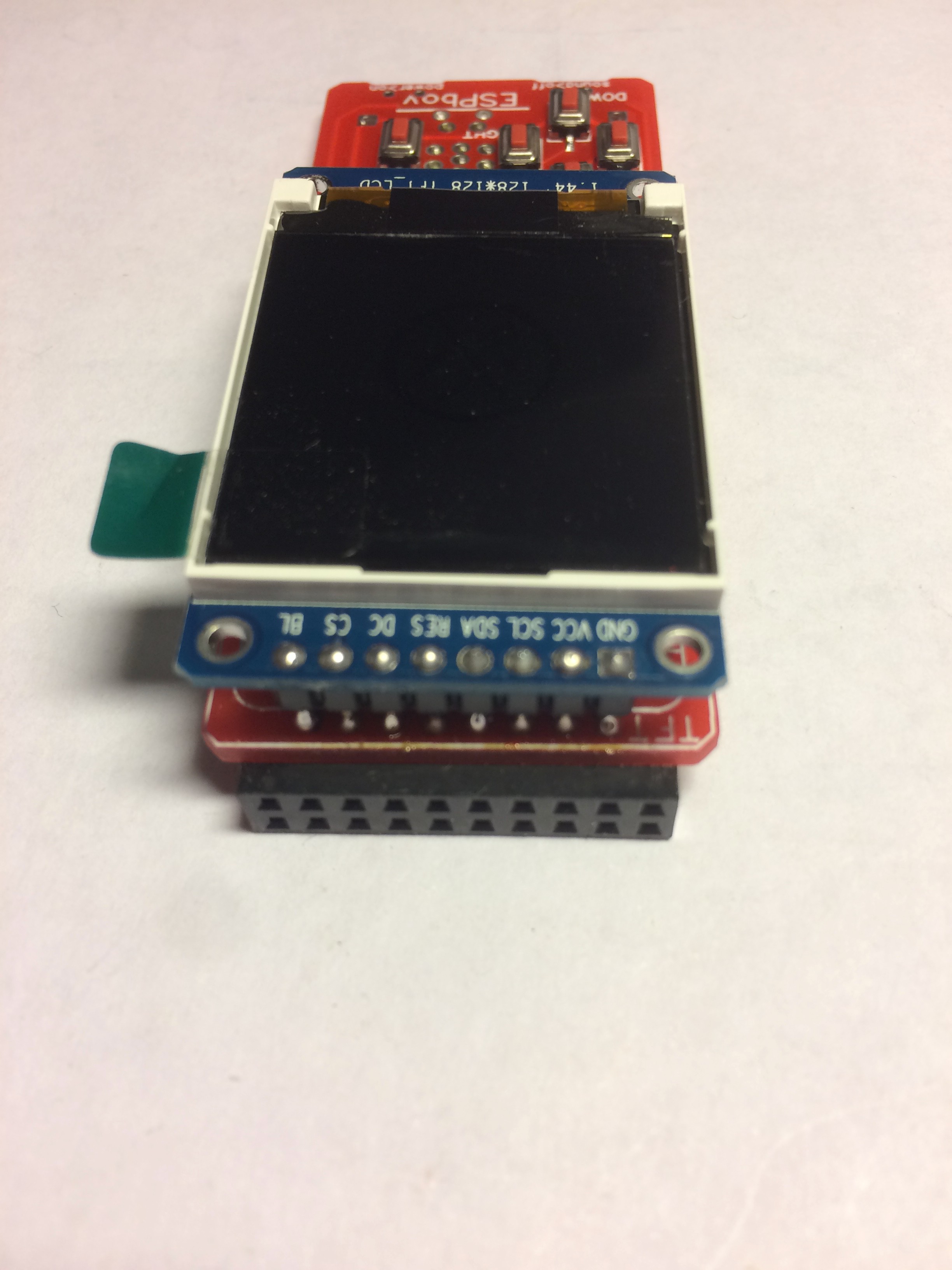
4. LCD display module
Official ESPboy Kit:

PCB with most of small components presoldered

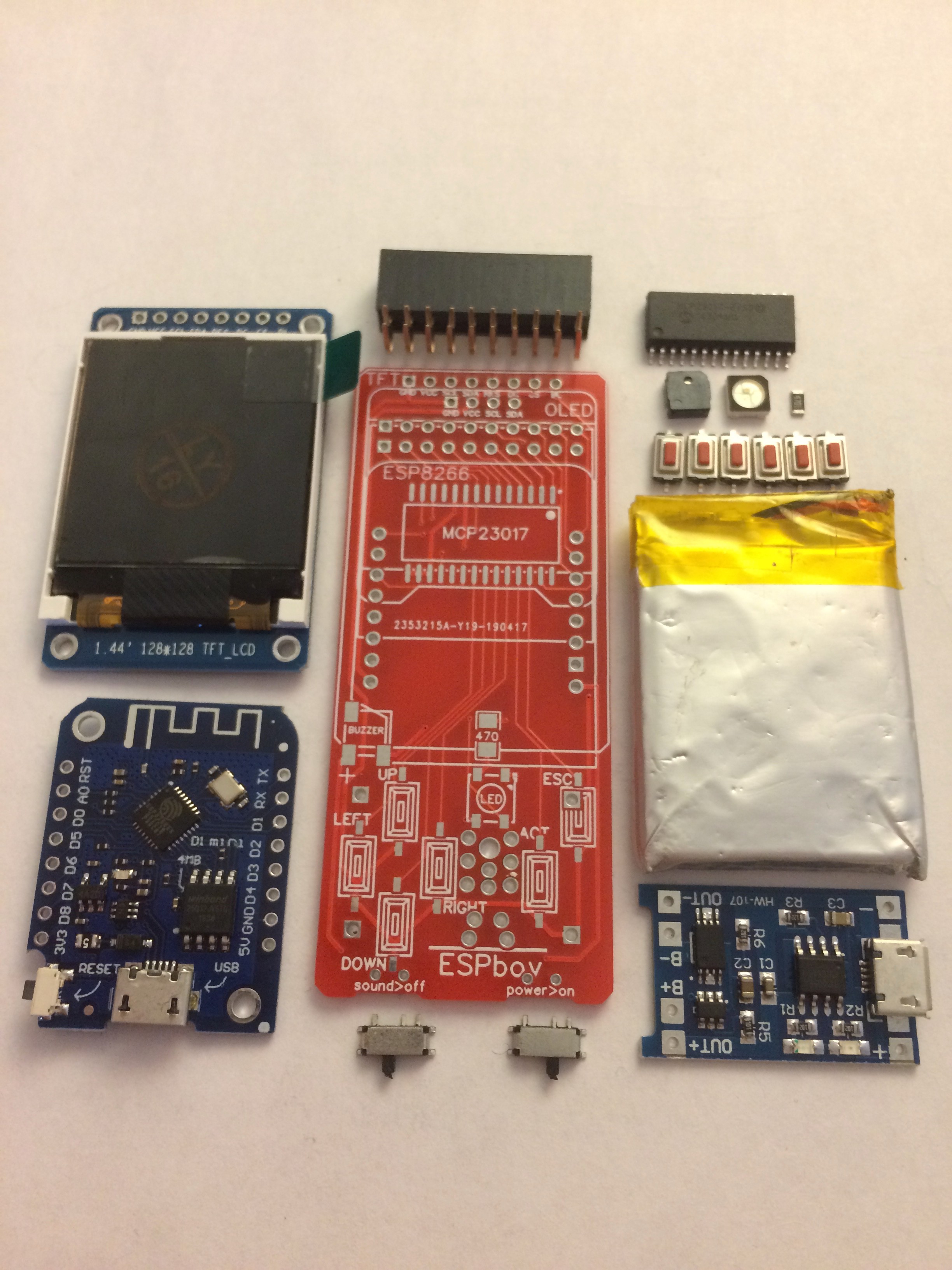
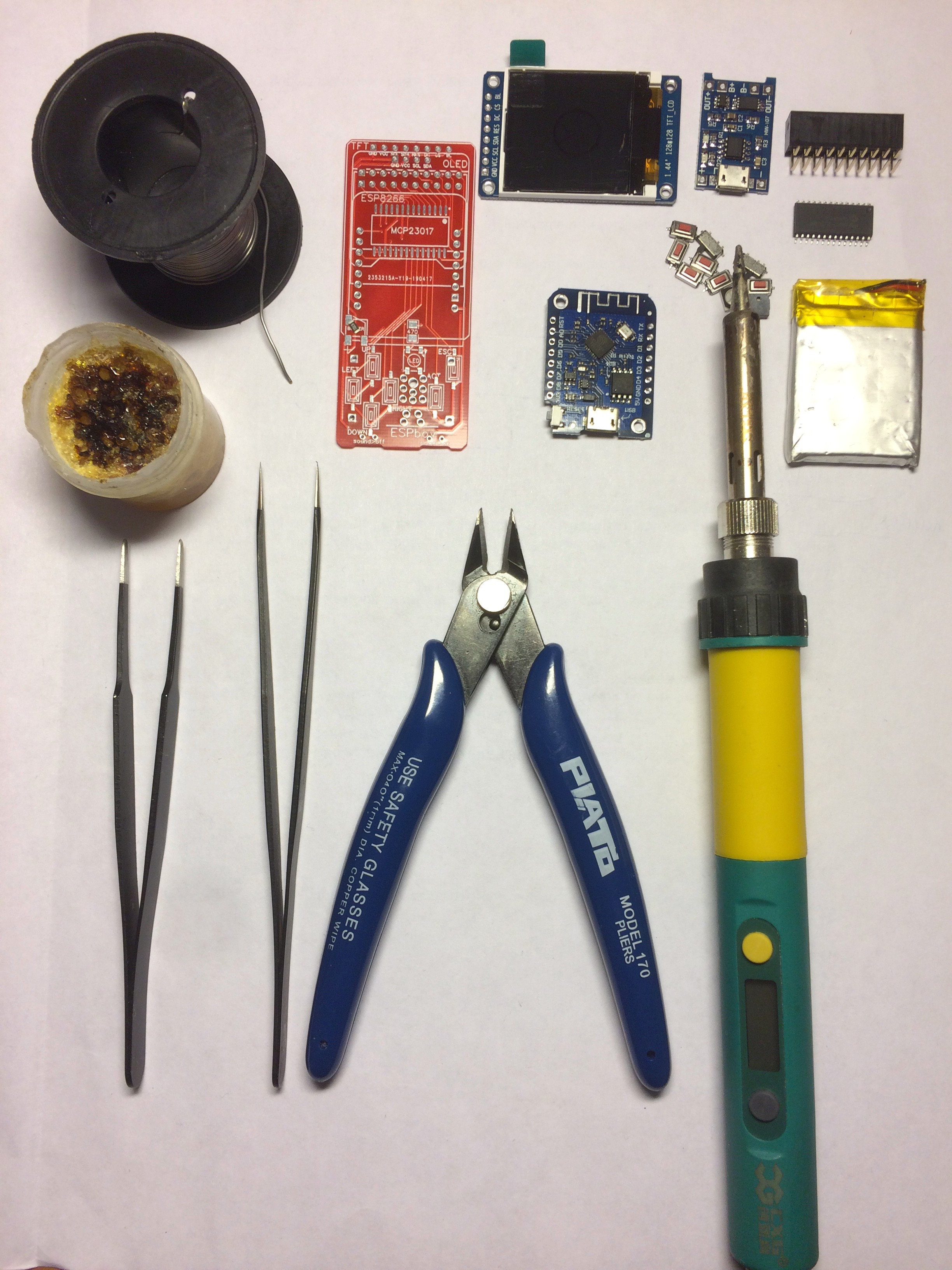
Or you can order the ESPboy PCB or buy it clean and also buy all components separately

-
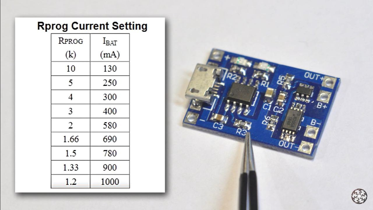
4Change R3 at TP4056 bat charger to setup right charging current
Change R3 resistor at TP4056 battery charger to set up battery charging current according to the table.
Charging current (I bat) should be half or less of battery capacity.
If your battery has 600mAh (check your battery), you have to setup charging current not more than 300mA by changing R3 to the resistor with 4kOhm or more, according to the table

-
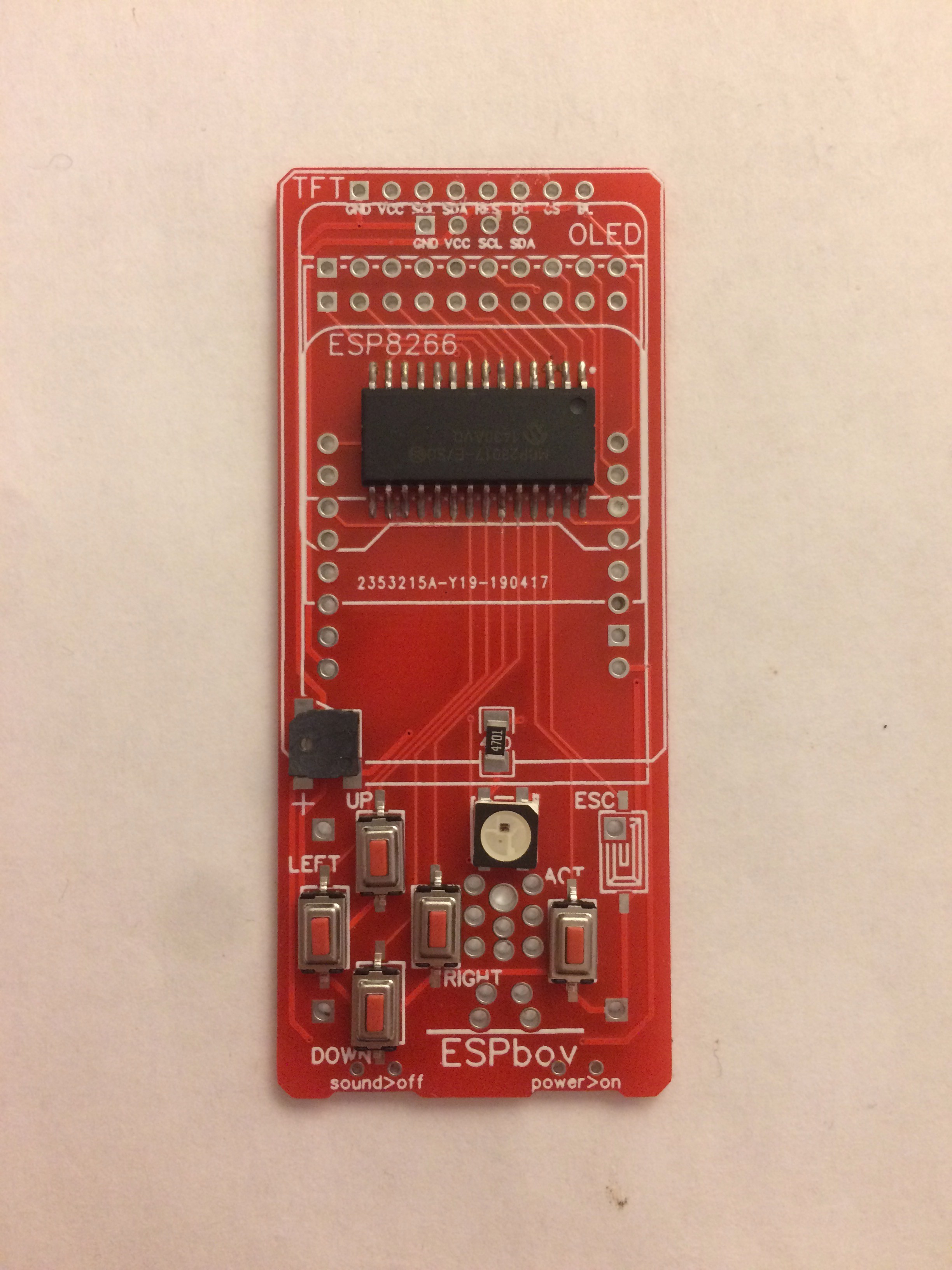
5Solder MCP23017, buttons (except one!), LED, buzzer (or speaker), resistor
The buzzer as you can see at the red PCB does not used in ESPboy anymore.
The speaker, amplifier transistor, variable resistor (for volume adjust) and fuze is installed in modern versions and no any buzzer.
Let's solder this parts.
First you have to unbend and straighten the speakers contacts, cut them a bit and solder on the back side of this PCB to the place marked "speaker".
PUT THE PIACE OF ISOLATING TAPE ON THE BACK SIDE OF THE SPEAKER
Than solder the transistor to the place marked "MMBT2222A" or "2n2222"
And solder variable resistor to the place marked A1 and fuze at the bottom edge of the PCB.
Don't forget to adjust the sound volume after the assembly.

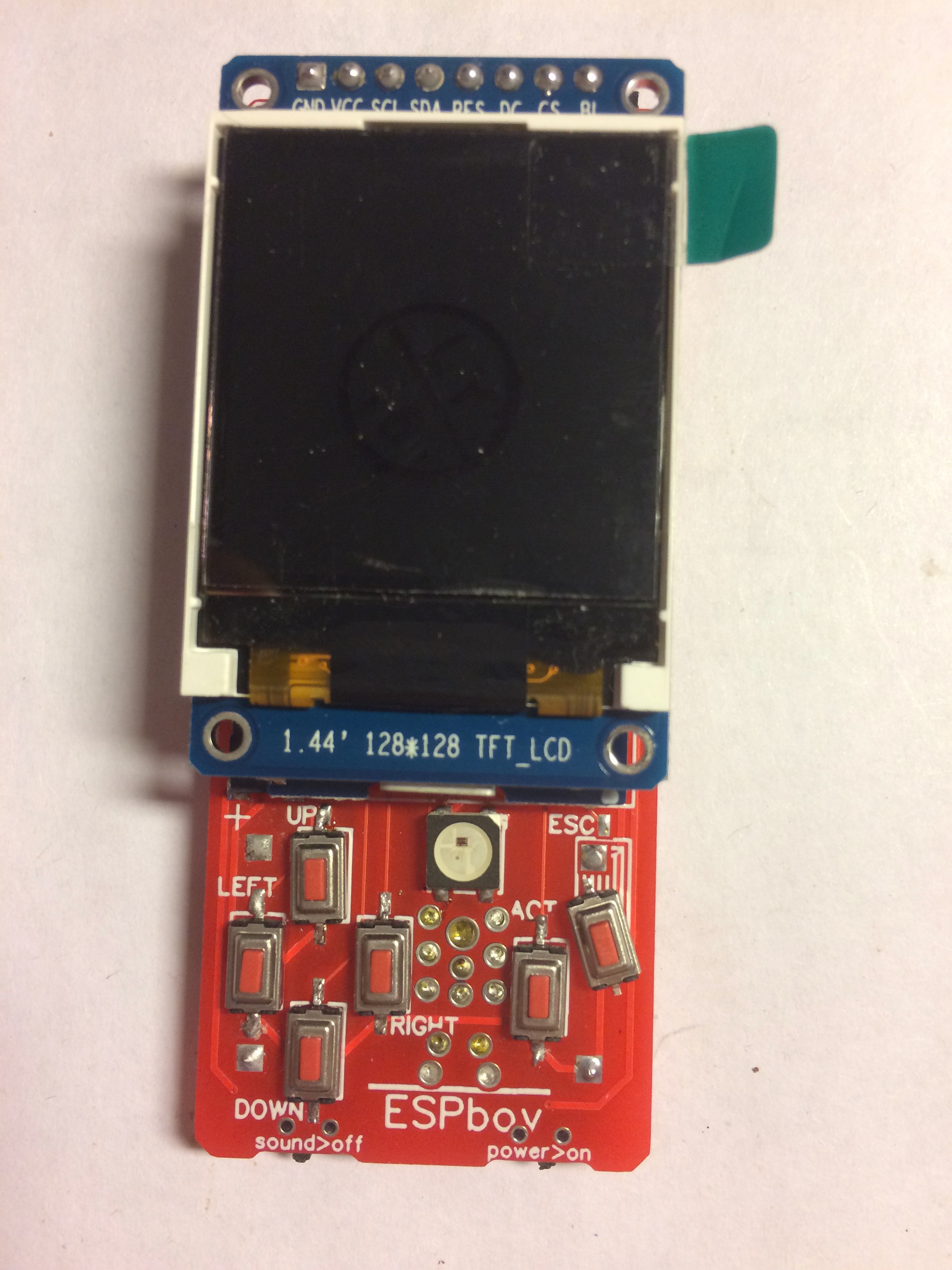
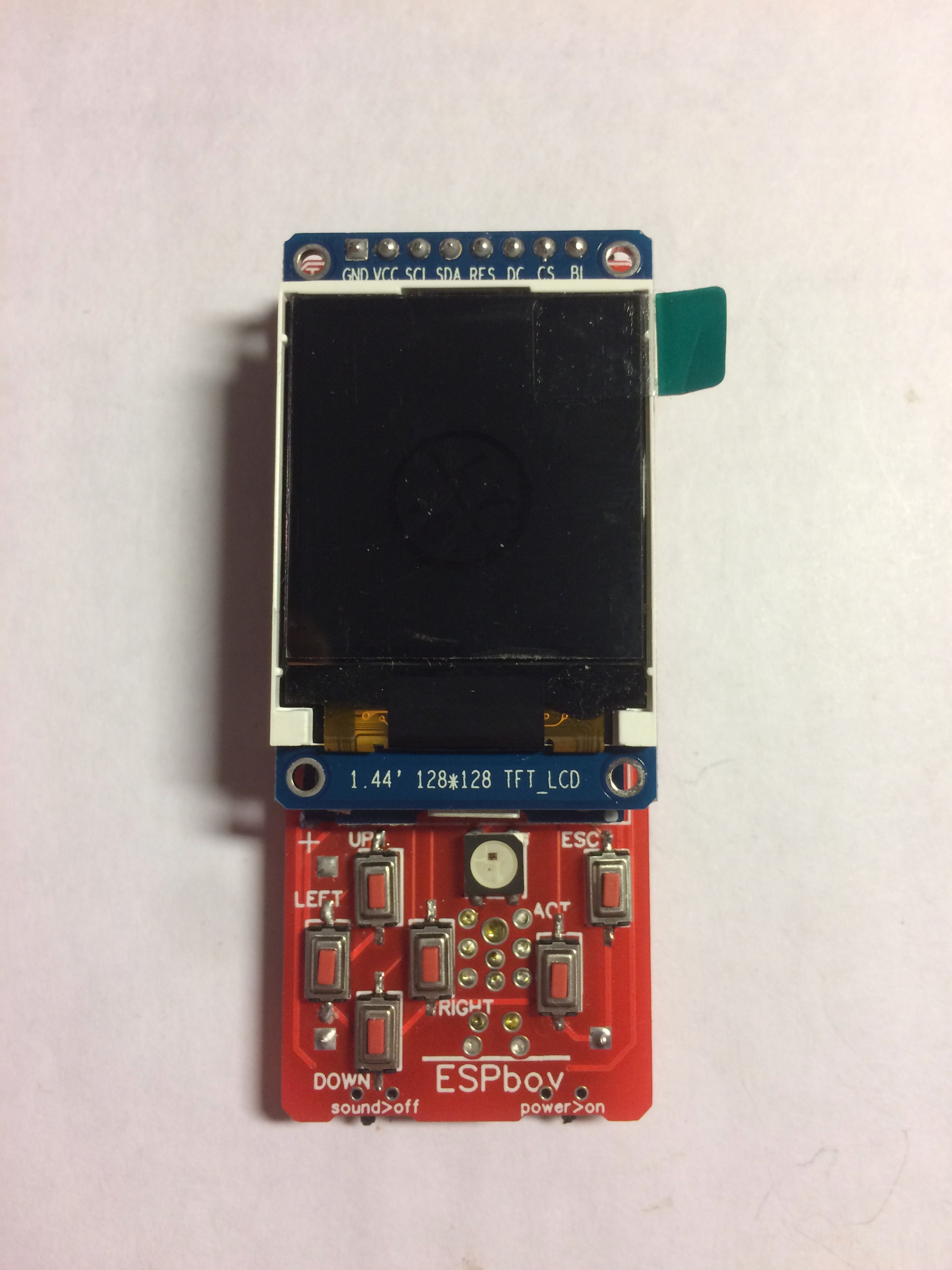
Following pictures continue to show assembly the old PCB with only buzzer version of ESPboy. The modern ESPboy PCB's does not supports the buzzer!

-
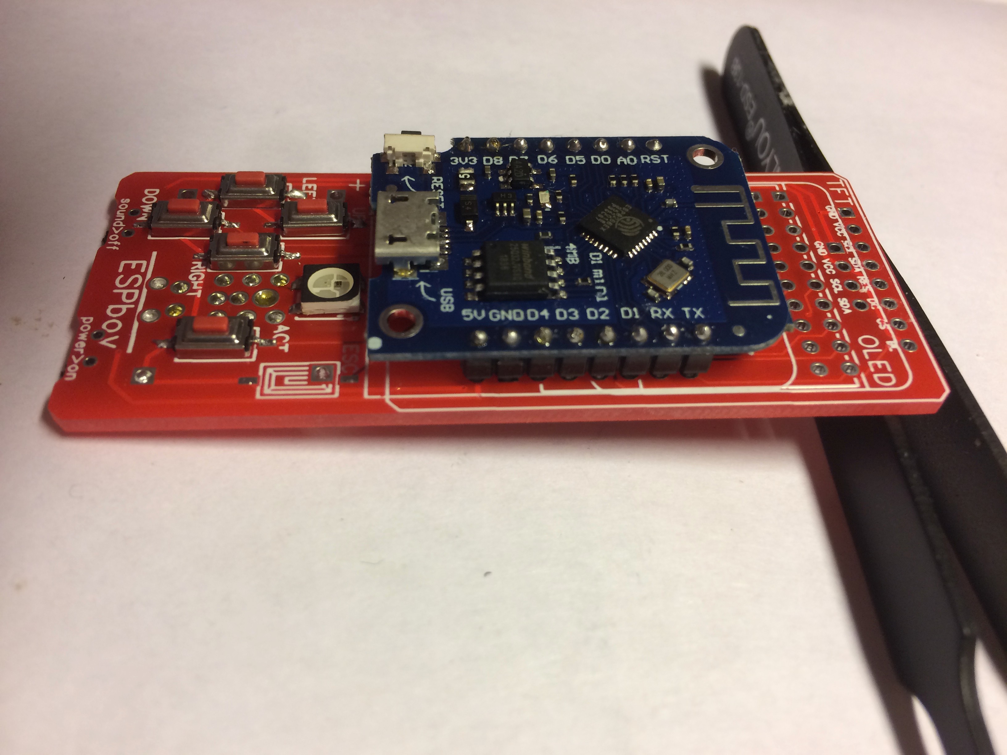
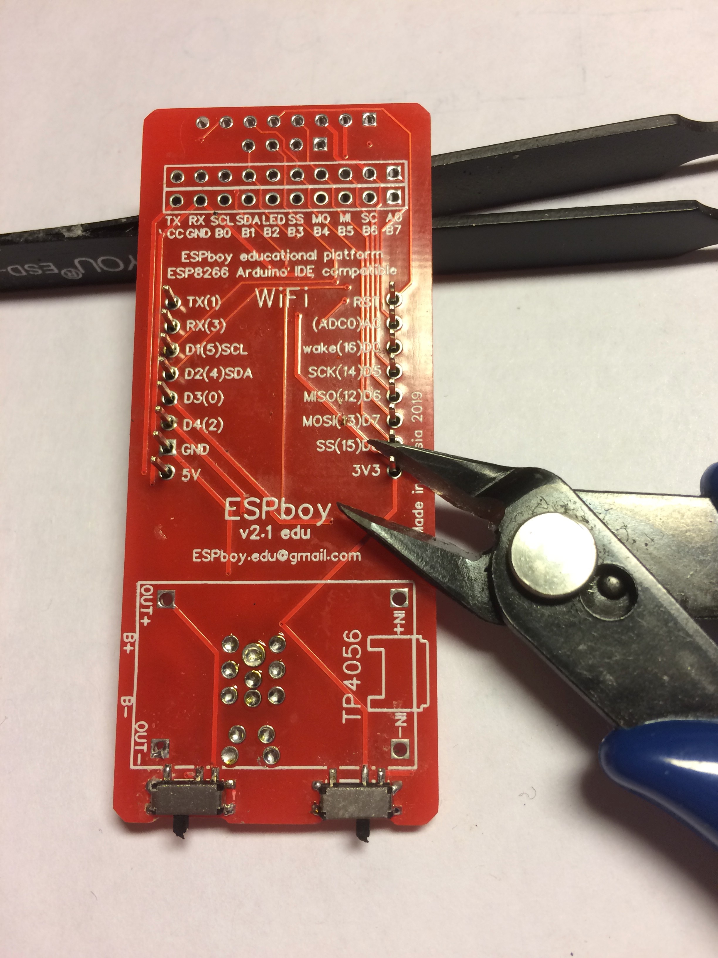
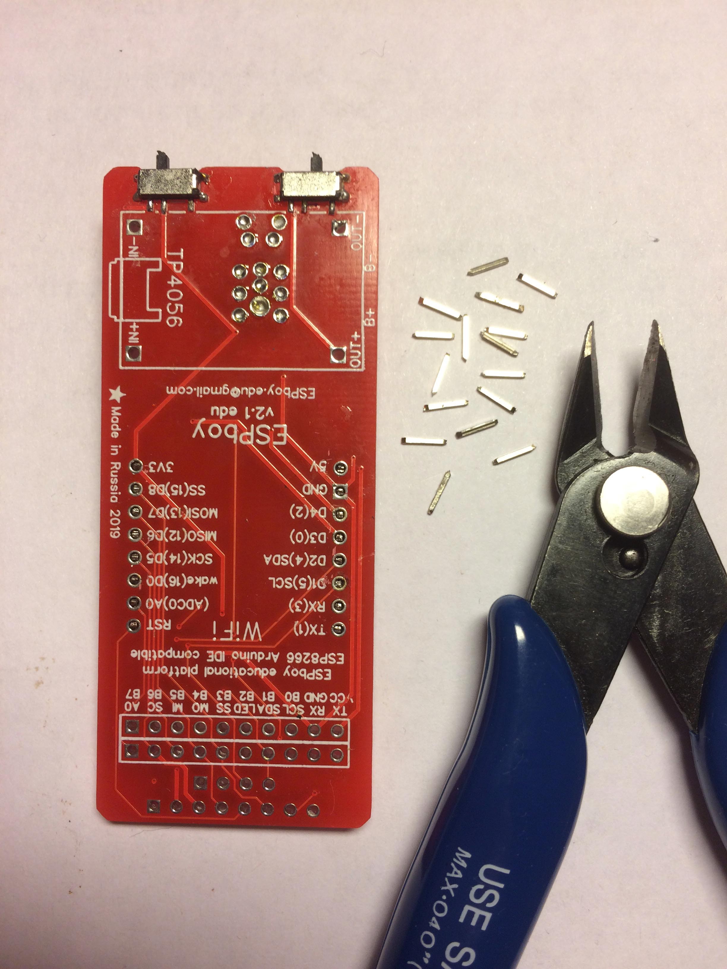
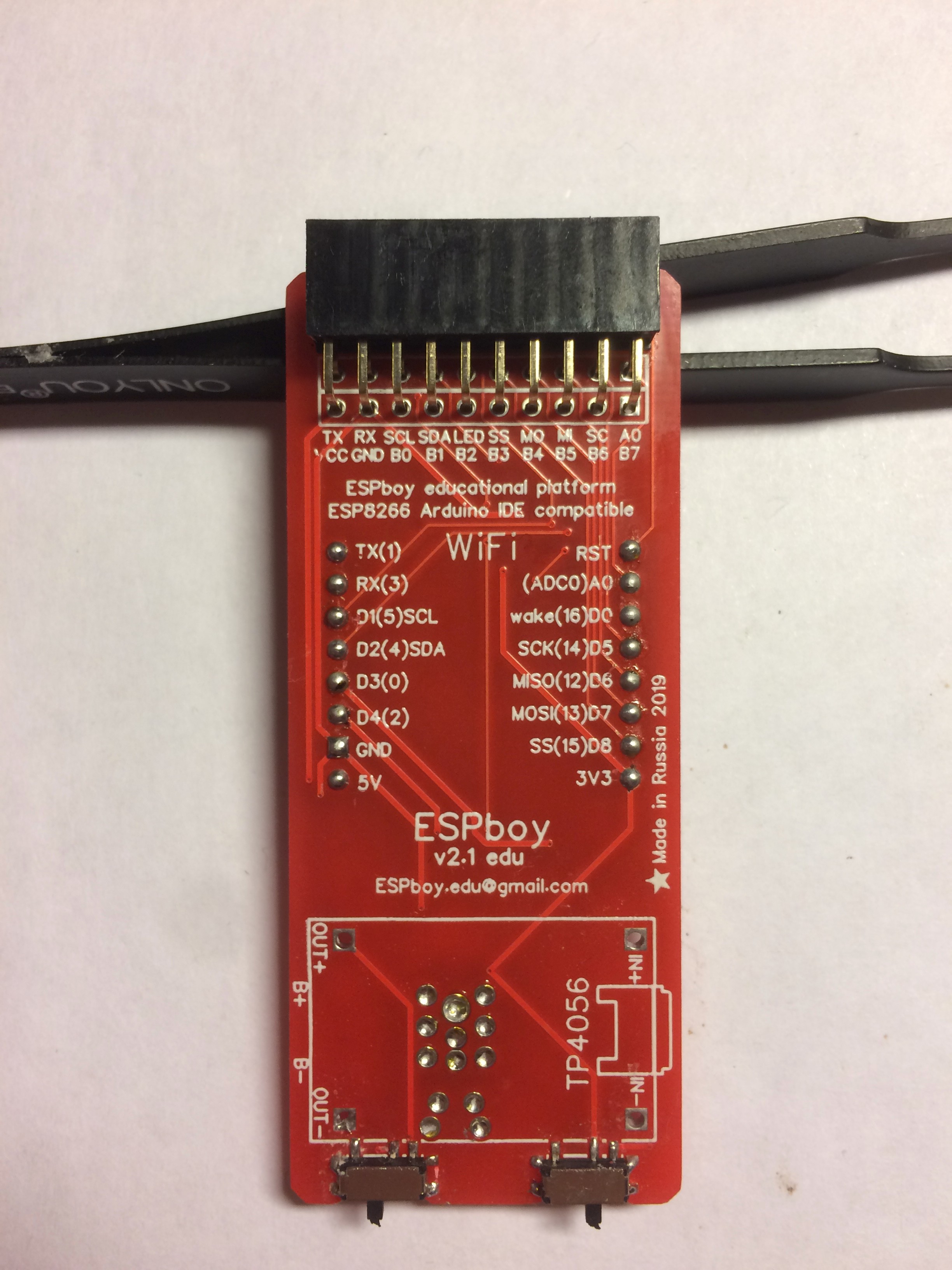
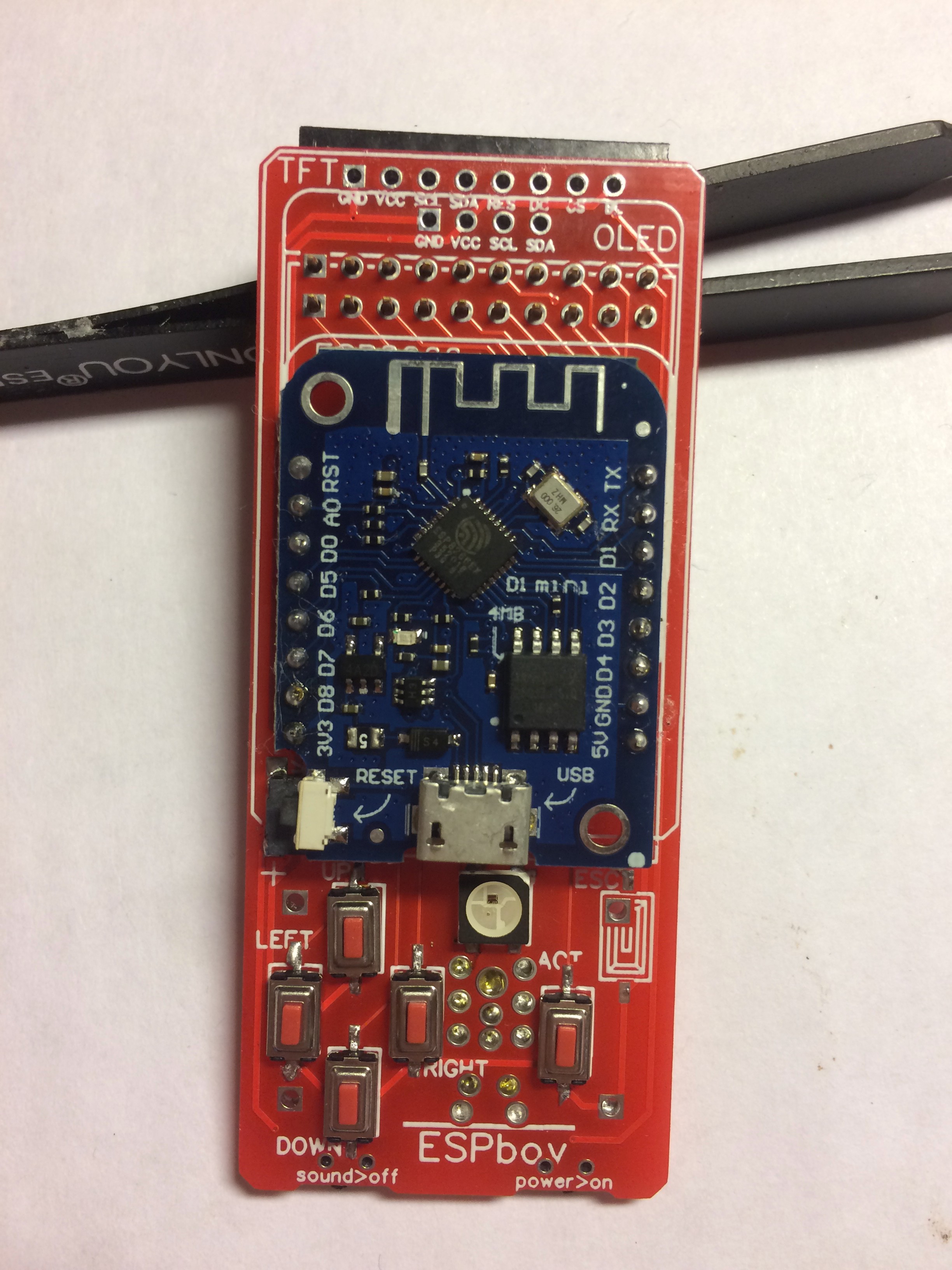
7Solder LOLIN (WeMos mini) microconroller and set header
ESPboy - RetroGaming&Software development MuliTool
For IT geeks, retro game fans, makers. Open source, portable, modular to explore, create, learn, code & play
 RomanS



Discussions
Become a Hackaday.io Member
Create an account to leave a comment. Already have an account? Log In.