-
Relational Operators
04/27/2019 at 07:31 • 0 commentsThe conventional relational operations compare numerical or boolean variables and return a boolean value based on the result of that comparison. The possible variations of relational operations are:
if a then...
if !a then...
if a > b then...
if a !<= b then... (same as above)
if a < b then...
if a !>= b then... (same as above)
if a >= b then...
if a !< b then... (same as above)
if a <= b then...
if a !> b then... (same as above)
if a == b then...
if a != b then...Further, a couple of new relational operator would exist. The first is:
if a == NEUT then...
Using '?' to represent this operator is nicely consistent.
if a then...
if ?a then...
if !a then...The second one is !! (ternary negation) which differs from boolean NOT. It returns FALSE for a positive input, returns NEUT for a 0 input and returns TRUE for a negative input.
In a boolean system some of these operations are redundant and aren't generally implemented in languages. These same redundancies exist in a balanced ternary system because the basic laws of arithmetic haven't changed.
The behavior of the relational operators is well defined in each language for booleans and integers, but needs to be explored when comparing a boolean and a kleene. As mentioned in other posts, I favor booleans that are forced to contain only a 0 or 1 rather than the "soft" booleans where any non-zero value is TRUE. This is how Python and stdbool.h in C do it. I also favor expanding this concept to the kleene data type so that only -1 is FALSE, only 0 is NEUTRAL and only 1 is TRUE. Any attempt to assign a kleene a different value would result in a negative value being clamped to -1 and a positive value being clamped to 1.
When comparing a kleene and a boolean there are a couple of things to consider. So far I have been considering that a boolean FALSE would continue to be represented by a 0 but I now realize this could cause serious problems such as:
bool x = FALSE //contains 0
kleene y = FALSE //contains -1x //returns FALSE
y //returns FALSEx > y //returns TRUE... uh oh...
x == -1 //returns FALSE
y == -1 //returns TRUE... dangx == y //returns... FALSE? Let me think about it...
Now how about comparing a boolean to a kleene:
bool x = FALSE //contains 0
kleene y = NEUT //contains 0x == y //returns TRUE... oh hell...
After some more consideration I now see that one of two things would have to happen. Either a boolean would have to use -1 as the FALSE value to avoid irrationalities like the ones demonstrated above, or the relational operators would have to do type checking and translate accordingly.
I favor the type checking approach rather than just asserting that -1 is the new boolean FALSE. This is because it would simply break too much code. Even the simplest things like "int x = 0" in C would break. So would any code that counts down to 0 and does comparisons to make a decision based on the countdown. Off-by-one errors would be everywhere. Therefore, type checking looks like the solution.
The next question is, if a boolean were compared to a kleene, what would the return type be? On one hand it could always be a boolean since every one of the above operators always resolves to either TRUE or FALSE. On the other hand, what would happen in a case like this:
boolean x = FALSE
kleene y = FALSEx = x == y //returns a TRUE... boolean?
y = x == y //returns a TRUE... kleene?This would definitely be language specific. Python doesn't have any problem with changing a variable's type depending on the situation. C++ just ignores you and leaves the variable type alone if you do something like trying to add 1.5 to an integer. In cases where the return value is not being assigned to an existing or newly instantiated variable then it would be fine to internally consider it a boolean in its limited scope. For example:
kleene x = FALSE
kleene y = FALSEif x == y
{do something...
}
The datum returned by the == operator is going to exist temporarily and with limited scope. It would probably be safest to consider it a boolean since that is the more limited of the two options.
As for comparing a kleene and a kleene, the simple answer is that the operators behave exactly as one would logically expect, and return either TRUE or FALSE, but not NEUT.
kleene x = FALSE
kleene y = NEUT
kleene z = TRUEprint (x > y)
FALSE
print (y >= x)
TRUE
print (x < z)
TRUE
That takes care of most of the relational operators but there is one more that is perfectly suited to a balanced ternary system. This is the "spaceship" operator that is generally denoted by <=> in the languages that support it. This is the "three-way" comparison. Let's say that the expression "a <=> b" is being evaluated. It returns an integer with a -1 if a is less than b, or it returns 0 if a is equal to b, or it returns 1 if it is greater than b. The only difference would be that in our hypothetical system it would return a kleene with a value of FALSE, NEUT, or TRUE.
if a <=> b == FALSE, then a < b
if a <=> b == NEUT, then a == b
if a <=> b == TRUE, then a > bRelational Operations Equivalent Three Way Operations
if a > b then... if a <=> b == TRUE then...
if a !<= b then... if a <=> b == TRUE then... (same as above)
if a < b then... if a <=> b == FALSE then...
if a !>= b then... if a <=> b == FALSE then... (same as above)
if a >= b then... if a <=> b != FALSE then...
if a !< b then... if a <=> b != FALSE then... (same as above)
if a <= b then... if a <=> b != TRUE then...
if a !> b then... if a <=> b != TRUE then... (same as above)
if a == b then... if a <=> b == NEUT then...
if a != b then... if a <=> b != NEUT then...if a then... if a == TRUE then...
if ?a then... if a == NEUT then...
if !a then... if a == FALSE then...
I know that the three-way operations look more complex and appear to be equivalent, but there is a difference. Based on some work I've previously done on the appropriate status flags needed for a ternary processor, it is possible to do any of those comparisons in a single operation. On the binary side, some of those take two separate comparisons, which actually means: do the first comparison, store the result in a register, do the second comparison, store the result in a register, compare the two results for the final answer, jump/branch or don't based on the result. Using the three way operators it would simply be: do the comparison, jump/branch or don't based on the answer. Six operations turn into two.
Ultimately, I think it will be this kind of thing that defines the difference between binary and balanced ternary systems. You just get more computation out of each action. The more I research it, the more this becomes clear.
-
Unary Operators
04/26/2019 at 07:19 • 0 commentsIn a recent post I introduced the Kleene data type as an addition to the boolean data type. In my hypothetical system both data types are available and bools would continue to operate exactly as they do now with 0 representing FALSE and 1 representing TRUE. Boolean logic works just fine on its own terms, there's no need to mess with it.
In this post I will explore how existing unary operators would work in a balanced ternary system and what additional unary operators are possible with a three valued system. Specifically, the ones that alter the value of a variable or return logical data about the variable. I will not address special purpose unary operators for casting, indirection, etc. and I will look at bitwise and tritwise operators in a later post.
Here are the most common unary operators and what they do:
x++ increments a numerical variable
x-- decrements a numerical variable
-x returns the negation of the value
+x returns the value
!x returns a boolean TRUE or FALSE value opposite the truth value of the variableThe logical negation operator (!) is the only logical operator on the list. It could be adjusted to return a kleene type instead of a boolean, but I don't think altering the behavior of existing operators is a good idea. The other four are arithmetic operators, not logical ones and would work the same way in a ternary system as they do on a binary one.
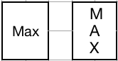
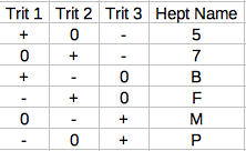
In a ternary system though, there are 27 unary logical operators. Of course many would be of little or no use, but all of them should be thoroughly explored. To talk about all these new operators we will need a vocabulary to use. It would be too complicated to figure out symbols for each operation and keep track of them so I will use function-style syntax and each unary operation is assigned its heptavintimal name. To reiterate, here are the heptavintimal (see my earlier post called "counting") values for each single-input gate and their truth tables:
![]()
For my immediate purposes in writing these posts I'll use the format "logic_x(variable)" indicating a logical operation as opposed to a tritwise operation with 'x' standing in for the hept name. Using this function/hept syntax, the way to perform a logical inversion on variable x is logic_5(x). When I later take a look at tritwise operators I would use tritwise_5(x) to perform a tritwise inversion on variable x. This formatting is just for clarity and probably wouldn't be well liked.
Applying any of these operations to a kleene would of course do exactly what the truth table above states. At this moment I am of the opinion that applying one to a boolean should cause a compiler error. It's probably best not to try to mix kleenes and booleans. If a boolean is adequate for your purposes, use one and apply existing operators. If the flexibility of a kleene would benefit you, use a kleene and apply the above operators as desired.
Example pseudocode snippets:
kleene x = TRUE
print logic_5(x)FALSE
kleene x = FALSE
print logic_5(x)TRUE
kleene x = NEUT
print logic_5(x)NEUT
The question is what would each one mean when applied to a numerical variable? The conventional NOT operator can be used on numbers and it has the property of treating the number as if it was a boolean. If the number was non-zero, its boolean negation would be FALSE and it returns a 0 value. If the number was zero, its boolean negation would be TRUE and it returns a 1. This behavior should remain unchanged.
Probably the most sensible way to do this is to follow that convention, but because the the 27 unary operators follow Kleene logic, they would return a kleene data type. They would treat negative numbers as FALSE, zero as NEUT and positive numbers as TRUE.
Example pseudocode snippets:
int x = 7
print logic_5(x)FALSE
int x = -4
print logic_5(x)TRUE
int x = 0
print logic_5(x)NEUT
The specific example of the logic_5() logical operator used above could be given its own symbol since it is the ternary equivalent of the boolean ! (NOT) operator and would probably be used fairly often. I would suggest !! for ternary negation which is specifically three-valued to distinguish it from boolean NOT which is only two valued. It would also act differently to boolean NOT when used as an arithmetic operator:
int x = 5
int y = -5
int y = 0print !x
FALSE //because x is non-zero
print !!x
FALSE //because x is positive
print !y
FALSE //because y is non-zero
print !!y
TRUE //because y is negative
print !z
TRUE //because z is 0 (boolean FALSE)
print !!z
NEUT //because z is 0 (ternary NEUTRAL)
-
Data Type Sizes and Memory Access
04/26/2019 at 06:56 • 2 commentsIn my previous post I proposed a series of primitive data types with only three possible sizes: 1 tryte (9 trits), 3 trytes (27 trits) and 6 trytes (54 trits).
Simplifying the number of data type sizes is not just an aesthetic desire for design elegance. It could also potentially improve the performance of reads from RAM. Conventional memory devices are designed to access chunks of data that are multiples of a byte. This is because reading from memory is agonizingly slow compared to the speed of a modern processor. If a memory device accessed each bit individualy it would have to do eight separate actions to store a single byte and each one of those actions would be at the same slow rate (slow compared to the processor). The most time-efficient solution would be to only ever deal with chunks of memory the same size as the largest possible data type. That way there is no decision making process or any need for multiple reads. However, this would waste lots of space since even a char would take up 8 bytes (64 bits).
There are various architectures, but most RAM devices take the middle road and store data in individual bytes (never bits) while providing access to 4 or 8 bytes at a time. These groups of bytes are called a chunk. If the processor is storing a char, it only uses one of the bytes in the chunk, a short would use two, etc. The problem is that this can lead to misalinged data storage. For example, an integer takes up four bytes but could span accross the boundry between two four-byte chunks in memory. When this happens the processor has to read both chunks in, then do a series of logical shifts on both chunks to remove the unwanted bytes from each chunk and finally combine the two chunks to recover the original integer. You end up having to perform half a dozen processor operations just to get the data you originally wanted to perform an operation on. Having fewer data sizes means fewer misalingments overall and fewer operations necessary to recover misaligned data.
If we use our 9-trit, 27-trit, 54-trit example above, a memory device that presented 3-tryte chunks (27 trits) would only have one boundary that could be crossed and only two ways to cross it. One way is that a 3-tryte data type could be misaligned with a 3-tryte chunk. The other is that storing a 6-tryte data type would always span two chunks, but might also be misalinged with the chunks and therefore span accross three chunks. Therefore, three reads would be needed to recover the data. This is analogous to a 64-bit double being misaligned with the 4 byte chunks in memory. The two chunks with most of the double would need to be read as well as the chunk with the overlapping piece of the double.
If a memory device presented 6-tryte chunks instead of 3-tryte chunks then both situations would still be possible, but in the case of the misaligned 54-trit data type, only two reads would be necessary since a 6-tryte variable couldn't span three 6-tryte chunks no matter how misalligned it was. The downside is that more shifts would be needed to correct a misalignment and more space would be wasted by data types smaller than 54 trits.
Of course, this all presupposes the availability of memory devices that not only store ternary values but also present chunks in multiples of three rather than two. In the meantime, an intermediary device to do translation between a prototype ternary processor and a conventional memory device wouldn't be exceptionally difficult to throw together. This would support proof-of-concept work on a ternary processor.
-
Primitive Data Types
04/26/2019 at 06:52 • 0 commentsPrimitive data types are an interesting subject to tackle. They are technically defined by programming languages, not hardware, so I am a little out of my field. Nevertheless, it's vital to explore the possibilities and variations that come about with a balanced ternary system. Everything I put forward here is really just intended to get some of my ideas documented. The implementation details would be up to the designers of the programming languages, a task I am not really qualified to undertake.
When I say primitive data type, I'm talking about the "C style" types that map directly to objects in memory of a pre-defined size (some portion or multiple of the processors word length). They can be manipulated directly by individual processor instructions, like in assembly. I am also limiting this post to value types and not reference types such as pointers, references, classes and such.
The hypothetical systems I am thinking about would have word lengths of 27 trits or 54 trits. These would far exceed the capacity of a 32-bit system or a 64-bit system respectively. In a previous post I said a 45-trit system would be sensible because it would exceed a 64-bit system and is divisible by both 3 and 9, but then I realized it is not an even multiple of 27. Moving up to 27*2=54 trits would probably be the next logical step up from a 27-trit word length.
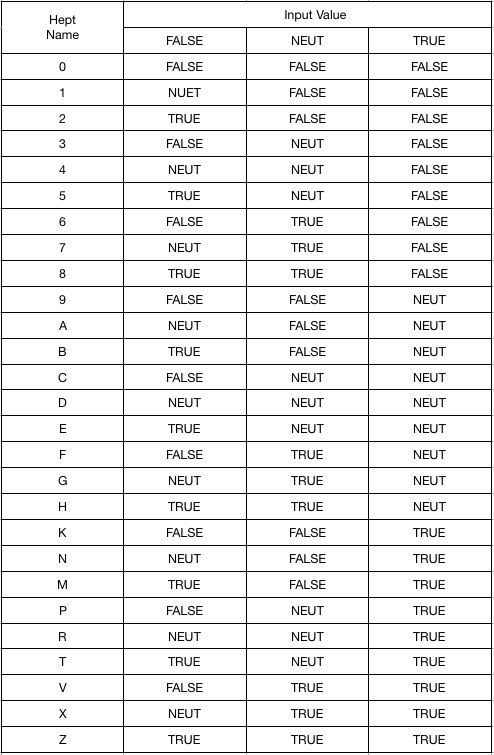
Let's start with the usual lineup of commonly recognized primitive data types. The values given are common mappings, but not necessarily true in all implementations. I'm using C style primitives because that is the lowest level programming language that most people are acquainted with.
![]()
Breaking this down, we have several integer types, either signed or unsigned of various sizes. Then there is a pair of special integer types for portability across systems that could have dissimilar word lengths. Next we have a special 8-bit type for ASCII characters. Then there are some floating point types and the boolean type.
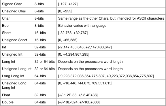
Now on to the primitive data types of our imaginary world where 27-trit and 54-trit balanced ternary computers, microcontrollers and digital signal processors are commonplace. First off, all this signed and unsigned stuff can go out the window! Balanced ternary numbers are natively signed or unsigned by their value alone. Therefore, we would only need the following integer types:
![]()
That handles signed and unsigned numbers well beyond 32-bit or 64-bit equivalents. The "word" type also allows programs written for the smaller architecture to run on the larger without worrying about weird integer problems. Just like with existing systems, programs written for the larger architecture could still get bugs due to truncation if compiled on the smaller architecture. The Tryte is useful to have because there does need to be an efficient scheme for packing arbitrary data.
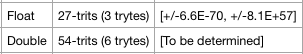
We would also need floating point number types:
![]()
The 27-trit float is not just in my imagination. A formal proposal has already been written and submitted for peer review. The 54-trit float is total fantasy at this point but that word length should be capable of exceeding the range and precision of the x86 80-bit double double. It would definitely not exceed the range/precision of a 96-bit or 128-bit long double.
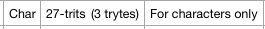
Next, we should have data types for human readable characters. I suggest a char type that is the full 27-trits but is explicitly not an integer. It would be large enough to hold a full-sized UTF-32 Unicode character. This could seem rather wasteful of space, but that isn't the same major concern it once was. Further, the 9-trit tryte exists and could be used to allow a string of tiny UTF-8 or ASCII characters taking up whole 27-trit chars to be efficiently packed if they needed to be transmitted or if space constraints were severe. That is more of a language specific implementation detail.
![]()
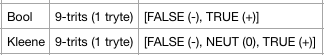
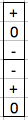
But how do we handle boolean values on a balanced ternary computer and how to handle the relative "truthiness" of 0 in a balanced ternary system? I propose two "factuality" data types:
![]()
Note that I am adopting NEUT or NEUTRAL as a label for the 0 value. I have been using "intermediate" in earlier posts, but it just takes too long to write and the abbreviation makes it look like you are talking about integers.
In some languages, like C (prior to C99) you don't have an actual boolean data type at all, but the comparison operators will treat integers with any non-zero value as TRUE and integers with a value of 0 as FALSE. With C99 you can include stdbool.h and get an actual boolean data type where any non-zero value that is assigned to it is changed to a 1 so that the variable can only contain a 0 or a 1. Python does essentially the same thing. I strongly favor the C99/Python way of handling bools and encourage the same behavior with Kleenes except that the FALSE value would be represented by a string of zeros followed by a - in the least significant trit, a NEUTRAL would be represented by all zeros and TRUE would be represented by a string of zeros followed by a + in the least significant trit.
One should be able to cast a bool into a Kleene with a 0 value converting into a - so that FALSE conditions are maintained as FALSE. A Kleene would have to have NEUT clamp down to FALSE or up to a TRUE if one were cast to a Bool. Or the compiler could just throw an error (seems like a better idea to me).
Using a three-valued bool-like data type is actually not very original. They've been around since the 70's and are currently used in many programming languages including Perl, PHP, Ruby, Haskell and others. It is currently in the C++20 proposal as well so we may be seeing it in C++ soon. These are returned by a special comparison operator, usually denoted by <=> or <==> (spaceship operator), which compares two values and returns an integer value -1 if x < y, integer value 0 if x == y or integer value 1 if x > y. In C, the functions strcmp, memcmp and qsort return the same thing. The output of these functions is essentially a kleene data type. A kleene however, would be general purpose, not just constrained to a few specialized comparison operators.
-
Gray Codes
04/21/2019 at 07:56 • 0 commentsGray codes are any bit (or trit, qubit, etc.) sequence that changes in only one position between any digit-pattern and the next. This included the transition between the last pattern and the first in the sequence. Each code represents a specific value, but not necessarily the same value as if you simply counted the bit pattern normally as a number.
There are a number of uses gray codes such as error detection and correction, modulating digital sequences onto analog signals (i.e. radio) and the transmission of data between components with different clock rates.
There are a number of different binary gray codes. Here are some examples for various lengths:
![]()
As you can see, each pattern in the sequence only changes in one bit position at a time. This includes the switch from the last position back to the first position.
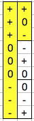
Let's see if you can do the same thing in a balanced ternary number system. I won't bore anyone with my path from "no clue" to "no problem". Instead I'll just jump straight ahead to the method I found to construct a balanced ternary gray code for any arbitrary number of digits.
First, we need to know which patterns of trits to throw out right away. Any pattern which does not include all three trit values (-,0,+) in equal numbers is obviously not going to work. So we can immediately toss out all patterns other than the following, given in sequence and with their heptavintimal name:
![]()
Any one of the above forms a 1-trit gray code by themselves. Thus there are 6 different 1-trit gray codes. To form a 2-trit gray code, simply take one of the above...
![]()
...follow it by another one that starts where the last one ends (two possible options)...
![]()
... and follow that by one more that starts where the last ended AND ends where the first one began...
![]()
...Now take the first of those three patterns, put it in the next most significant digit position, and stretch it out to three symbols for each symbol...
![]()
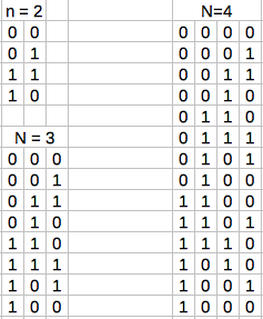
... and voila! You made a 2-trit gray code! How about 3-trits? Take your existing code and now copy the least significant digit position twice more, tripling it's length...
![]()
... now remember how we stretched out the first triplet in the 2nd digit position? Do that again with the second and third triplets.
![]()
... and finally take the first symbol, place it in the next most significant digit position, and strrreeeccchhh it out to 9 symbols per symbol...
![]()
... and you have a 3-trit gray code. Wash, rinse, repeat. Want an 847 billion value gray code? Just keep doing that until it is 25 trits wide. Or more, or whatever. The figures to the right show the pattern of changes as being regular and consistent.
As a side note, as long as you consider that swapping from - to + or from + to - is a shift of only one degree, then every ternary gray code is also only shifting one degree of value at any given time. If you consider that such a transition is shifting two values, then some transitions (like - to 0) are 1 degree while others (- to +) are two degrees.
-
More on Ternary Logic
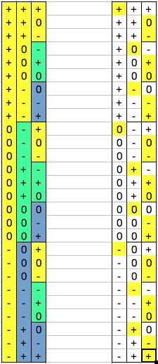
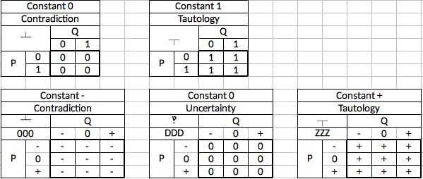
04/20/2019 at 07:16 • 0 commentsTo wrap up the subject of logic (for the foreseeable future), this is an enumeration of the 16 binary connectives and their Kleene logic equivalents as well as a few extras. The Kleene truth tables given here consist of the original four that Kleene defined with the remainder being logically consistent extensions that follow the same pattern while matching up against the remaining binary connectives. Thus we have one balanced ternary connective that corresponds to each binary connective.
I include the gate name, logical connective name, traditional logic symbol for that type of connective and the truth table. On the ternary gates I also include the generic three number/letter name.
![]()
As you can see there is one additional connective which I have named "uncertainty". It always outputs an uncertain value. I have assigned the interrobang as its logic symbol (naturally). Of course, these connectives have no logical usefulness so they are only included for the sake of completeness.
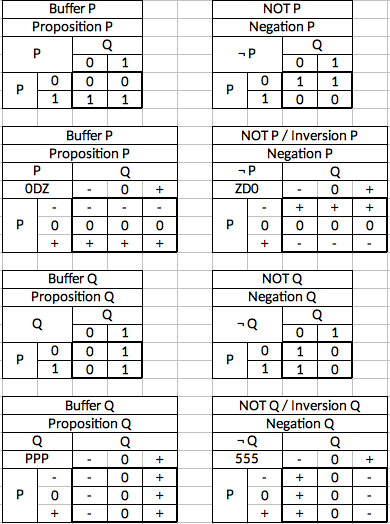
![]()
These gates also have no particular use but are documented regardless.
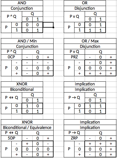
![]()
These are the four connectives explicitly defined by Kleene as ternary extensions to the existing binary connectives. These are covered in detail in the post previous to this one. The only new data here is the ternary gates generic names and the symbolic logic symbols for the connectives.
![]()
These gates are the inversion of the AND gate and the OR gate. The ternary versions are not connectives explicitly defined by Kleene, but are logical extensions of them.
![]()
These gates are the inversion of the XNOR gate and the Implication gate. The ternary versions are not connectives explicitly defined by Kleene, but are logical extensions of them.
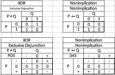
![]()
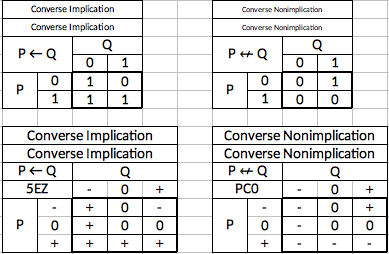
And finally, two gates which are not trivial, but which are not defined by Kleene or simply inversions of gates defined by Kleene. Nevertheless, the ternary versions of the binary connectives can be logically deduced. Where implication is the truth table for the rule "If P is true, then Q cannot be false", Converse Implication is the truth table for the rule "If P is false, then Q cannot be true". This is not the inversion of Implication, but rather a reversing of its logical assertion. Converse Nonimplication is simply the inversion of Converse Implication.
Finally, we'll take up two alternative gates that Kleene developed in later years are part of a system eventually known as "weak Kleene logic". In these, the basic logical structures are the same except that an uncertain input always "casts doubt" on the result. In other words, an uncertainty ALWAYS results in an uncertain output. He explicitly defined the truth tables for conjunction (AND gate) and disjunction (OR gate). I include them here as well as their inversions. We can call these the weak Min, weak Max, Weak NAND and weak NOR.
![]()
That's it for symbolic logic! I don't plan to come back to it unless there is some compelling reason, but we will see some of these concepts again when it is time to look into
bitwisetritwise operations. -
Ternary Logic
04/19/2019 at 07:21 • 0 commentsIn earlier posts I made some comments about using Kleene logic in ternary computer systems and that it was "more appropriate" for balanced ternary math. These statements could be misleading and this is a good place in the sequence of documentation to take up the subject of logic and logical operations in a balanced ternary computer.
Boolean logic has it's roots going back to the classical era, but was initially formalized by George Boole in the 1850's as a mathematical approach to human thought. Boole proposed that statements or concepts could be either true or false and that, using some logical conclusions based on truth or falsity, you could perform mathematical operations on non-mathematical subjects. The key here is that this was originally intended to be a philosophic tool, not an engineering one. That's why the terminology may seem a bit unfamiliar.
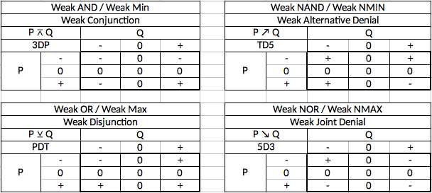
What we now call "boolean algebra" is actually a well defined set of extensions to Boole's work. The 16 possible binary gates come from this algebra. In the field of formal logic these gates are called "connectives". Let's take a look at these logic gates again, but this time in the context of formal logic. Note that the inputs in logic texts are traditionally denoted as P and Q instead of A and B.
![]()
As gone over in my post on 2-input gates, most of these gates are either logically useless, or are redundant. The redundant ones can be built using one or more of the other gates in combination with the 1-input inverter.
When we are trying to extend this system to include a third value, what we want is a logic system where the equivalent ternary connectives are "most-like" the most commonly used binary connectives. From my research, the ternary logic system most closely approximating binary algebra is Kleene logic.
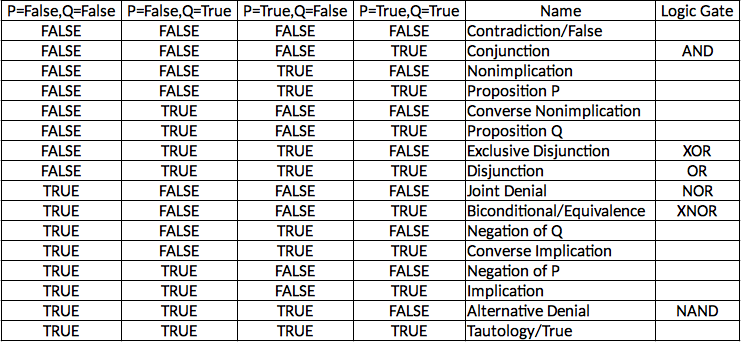
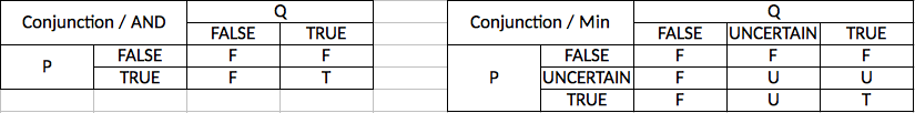
Kleene's thee-valued logic originally only included connectives that corresponded to Conjunction (AND gate), Disjunction (OR gate), Biconditional (XNOR gate) and Implication (no common gate for this, but it is equivalent to "B OR Not A"). The rest of the 16 connectives can be deduced from these four. Let's compare them to their binary equivalents:
![]()
As you can see, there is a close similarity between the two. Anything with a false input results in a false output and only where both inputs are true is the output true. An uncertain input denies a true output but does not overide a false one. Thus the definition of conjunction (a joining or union) is required to achieve a true output. Also, both connectives have the effect of outputting the lowest input. This is why the ternary version is referred to as the Minimum gate, or Min gate.
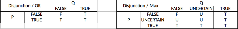
![]()
In this case, the similarity is still there but the effects are reversed. Anything with a true input results in a true output and only where both inputs are false is the output false. An uncertain input denies falsity, but does not override a truth. Thus the definition of disjunction (a separation or lack of union) is maintained by allowing a true output even in the face of disagreement. Both have the effect of outputting the highest input. There ternary version is referred to as the Maximum gate, or Max gate.
![]()
Here again, we have a strong similarity. Where the inputs agree unambiguously the output is True and where they disagree unambiguously the output is false. Where an uncertain input is present, the agreement or disagreement cannot be determined and the output is uncertain. I don't know of anyone having coined a really appropriate name for this gate so I am currently just referring to it as the XNOR gate, the same way I would the binary version.
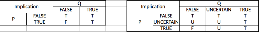
![]()
As expected, there is similarity here as well. The entire concept of logical implication can be summed up as "if P is true, then Q cannot be false". As we can see, the binary version expresses this as the output always being true except in the one case where P is true, but Q is false. The Kleene logic interpretation is predictably extended to three values where the basic law remains the same but we get an uncertain output if it cannot be determined with certainty that both conditions of the law have been met. With this gate, there isn't even a binary gate name to steal, so I'm just borrowing the Boolean algebra name and calling it the Implication gate, or Imp gate.
When you get down to practical application, the "choice" of ternary logic systems turns out to be mostly a matter of labeling. Remember, all 19,683 possible two-input gates could be produced and used. That means that *any* ternary connective from any three-valued logic system can be produced with ternary circuits. Therefore any ternary logic system can be implemented if desired. Maybe an alternative system will turn out to be extremely useful in some niche application. In that case it can be implemented without great difficulty. We aren't really limiting ourselves by using Kleene logic, we're just picking Kleene's terminology for which truth table corresponds to which binary gate.
A later post will enumerate all of the ternary equivalents to the 16 binary connectives, two more connectives proposed by Kleene at a later date, and some additional gates that follow logically from the others.
-
Two Input Gates
04/17/2019 at 07:37 • 0 commentsBefore getting into the ternary 2-input gates, it is useful to review the binary 2-input gates for comparison. Binary 2-input gates have two inputs, each of which have two possible states, and have an output with two possible states. This means that there are 2^2=4 possible input conditions and 2^1=2 possible output conditions for a total of 2^4=16 possible gates. These gates are:

The six gates with all upper-case names are sometimes called the "named gates" and are generally the only ones used in circuit design along with the single input NOT gate (binary inverter).
Six of these "gates" aren't really gates at all: Constant 0, Constant 1, A, B, Not A, Not B. Constant 0 and Constant 1 are just a value with no modification. A and B are just the A or B input itself without any modification. Not A and Not B are the same as a single-input inverter placed on the wire in question. These six gates don't actually have any logical value as two-input gates.
The six gates with a star are universal gates, meaning that all other gates can be created using combinations of just the one type of gate. You may read in some places that the NAND and NOR gates are the only universal binary gates but this is not strictly true. NAND and NOR are the only ones that are in general use but the two "A AND/OR Not B gates" and the two "B AND/OR Not A gates" are also universal. However, they can be created using one of the other "named gates" and one or more inverters. It's much easier to just ignore them and only use the named gates and inverters.
The above data are enough to form the basis of all binary logic circuits. The amazing thing is that this is a small enough data set to keep in your head, but is powerful enough to build any circuit of any complexity that doesn't require memory (more on that in a later post).
This is not the case with ternary 2-input gates. With these, each gate has 3^2=9 possible input conditions and 3^1=3 possible output conditions for a total of 3^9=19,683 possible gates. These gates are... just kidding, I'm not going to list them all. The scope of the data set is large enough that just talking about it requires the standardization of some vocabulary and a consistent way of representing the gates.
First, I represent a truth table like so:

The input labeled A can be -, 0, or +. The same goes for input B. The output is whichever of the nine x's matches the inputs. If A is + and B is -, then the bottom left result is the output. As with the names of the single-input gates, I have borrowed this format from Dr. Douglas Jones from the University of Iowa.
Here is a real example of a Min gate (minimum gate) which computes the lesser of the two inputs.
 Gate")
Easy!
Naming gates also needs some attention. First, I devised a way of giving each of the 19 bazillion gates its own unique name without overlap or having to memorize much of anything. You take the output box of nine values and divide it up into 3 rows. Each row now has a pattern of three trits. As detailed in my earlier post on single-input gates, each of the 27 possible sets of three trits has a unique letter or number assigned to it using the heptavintimal (base-27) number system. Thus each two-input gate has a generic name consisting of exactly three letters and/or numbers. The Min gate above has the following horizontal patterns from top to bottom:

Therefore the generic name for a Min gate is a 0CP gate. This way you only need to memorize or have a reference table of 27 different symbols in order to uniquely identify the 19,683 different gates.
Of course some gates will be used far more often than others and it is convenient to have colloquial names for those. In this case, unlike boolean gates, I have adopted using first letter capitalization instead of all letters capitalized. This is to avoid confusion between a generic name and a colloquial name. For instance, there is a common gate called the Max gate which is the opposite of the Min gate. It calculate the largest of the two inputs. However, M, A, and X are all valid heptavintimal values, meaning that MAX is a valid generic gate name. To avoid confusion, generic names are all-caps and colloquial ones are first-letter capitalized only. I expect that over time, more gates will gain de-facto "official" names which is just fine. I simply wanted to ensure there was a way to keep it all from getting mixed up.
Let's get a few obvious things out of the way. Several gates have no logical value. Examples are the three gates that always output the same value and the two gates that alway output one of the two inputs.
As for universal gates, there are 3,773 of them. Thanks to the good people at http://twistedoakstudios.com/blog/Post7878_exploring-universal-ternary-gates for figuring that out so I didn't have to! With over 19,000 gates to choose from and almost 4,000 of the universal, there is a wealth of options for any need.
Finally, a word on logic diagrams. It is obviously not worth it to try to come up with special symbols for each gate because nobody would ever be able to tell them apart. Instead, I favor a simple box with the name of the gate inside. If it is using a generic name, the all-caps letters would go from top to bottom. If it is a colloquial name, the letters would go from left to right and only the first letter would be capitalized. That would help keep them from getting confused while also reinforcing the top row, middle row, bottom row sequence of generic naming.
![]()
-
Ternary: Past and Present
04/14/2019 at 20:06 • 0 commentsCalling this a "history" would be misleading. I'm not trying to set forth a comprehensive chronology of the development of ternary logic or technologies. Rather, I simply want to quickly mention some of the key aspects of ternary development. The point is to make it better understood that, while the combination of binary circuits and boolean logic are the dominant digital technology, they are not the only digital technology that has ever been implemented. Every single component needed to build a microprocessor has been implemented with ternary technology at some point in time. It can be done because it has been done. It just hasn't become popularized or mass produced. It may never be, but that doesn't mean it's not interesting to try.
With that being said, let's take a look at the development of digital technology in general. Note that I use the term digital in its strictest sense. It only implies discrete values, not necessarily binary values. I consider that modern digital technology required the junction of two previously unrelated sciences. One was electronics and the other was formal logic. Before Claude Shannon became known as the father of communication theory, he was working with telephone switching equipment. Even earlier than that he had been exposed to the then little-known Boolean logic. In 1937 he made the connection that binary telephone switches could implement Boolean logic and therefore could be used to do algebra and arithmetic. Analog computers already existed at that time, but this revelation wiped them into obscurity and paved the way for the digital revolution. From that point forward, the combination of binary circuits and Boolean logic have been essentially synonymous with digital computers.
When I talk about ternary computers, I am talking about the combination of ternary circuits and Kleene logic. Kleene logic is named after Stephen Cole Kleene (pronounced KLAY-nee), who is probably better known for inventing regular expressions and for his work with Alonzo Church on lambda calculus. It is a system largely based on De Morgan algebra. It was developed over time, but the key point is that by 1938 Kleene logic formally incorporated the concept of an uncertain or unknown value and handled them in a predictable and consistent way. Also very important is that Boolean logic fits in as a subset of Kleene logic without alteration. Every Boolean logical function works as expected within the larger context of Kleene logic.
Kleene is not the only mathematician to extend Boolean logic to more than two values but I chose his formal definitions as the most appropriate for a ternary computer. This is because, if you map the values False, Unknown, and True into the balanced ternary numerical values -1, 0, and 1 and then do arithmetic with them, they come out correctly. Other multi-valued logic systems I studied were not consistently appropriate for balanced ternary arithmetic.
If we look at the types of instructions that a processor actually executes and skip all the ones that relate to the operation of the computer itself (I/O, interrupts, program flow, etc.) you pretty much just have math operators and logical operators. In my concept of a ternary processor, math operators are balanced ternary arithmetic and logical operators are Kleene logic. I won't go into Kleene logic itself because the parts that actually pertain to computing will be explained in a later post on 2-input gates.
That pretty much wraps it up for the logic part of a ternary digital computer system, but what about the hardware? It turns out that there has been much more development in this area than most people realize.
In 1840 an Englishman named Thomas Fowler built a fully functional wooden calculator that used balanced ternary arithmetic to simplify tax assessment calculations. Along with this, he published a pamphlet detailing addition and subtraction algorithms in balanced ternary.
Between 1958 and 1970 Nikolay Brusentsov built at least 50 fully functional balanced ternary computers at Moscow State University. Every part of these computers worked on the principals of balanced ternary arithmetic except for main storage. Some documents suggest that these were natively binary and translation between binary and ternary was done with intermediate I/O devices.
Storage devices such as ROM, RAM, Flash memory, etc. that use three or more values per storage element have been consistently available since at least 1984. The SSD's in modern computers can store up to 16 different values per storage element.
A vast array of communications protocols use anywhere from 2 to over 500 different values. In the field of radio communication, above-binary modulation has been ordinary for decades.
Ternary flip-flap-flops, 1-input gates, 2-input gates, sample-and-hold circuits, etc. have all been demonstrated with CMOS, NMOS, analog switches, multiplexors, discrete transistors, voltage comparators, op amps, etc. They have even made their way into some commercial products (I've found ternary circuits in some signal switching chips).
So if non-binary storage device, non-binary I/O devices, , non-binary modulation methods and non-binary signal control devices exist in use today, why isn't it more obvious? It's because processors are all still binary and these other devices are required to do translations between binary and whatever non-binary system they happen to use. Next time you plug in your Samsung SD card, you could be using a binary device, an 8-level device, or a 16-level device. They are all powers of two because that makes the translation easier, not because some other number of levels isn't feasible.
As far as I can tell, the real reason so many things have gone non-binary, but processors haven't, is because of cost/benefit analysis. It makes sense for a serial communications chip to use more signal levels if it makes it faster without introducing errors. The comm chip doesn't need to do math or logic on those values. But processors need to process numbers. The manipulation of these numbers is their whole purpose and the decades of research and development that have been put into getting every last scrap of performance out of the binary/boolean system would be wiped out in a second if they switched to another number base.
Existing math algorithms wouldn't work, new logic problems would crop up, new physical engineering problems, etc. etc. etc. Everything from sorting algorithms to parity checking would have to be rebuilt from the ground up. It took decades just to get everybody to agree on a floating point standard and nobody wants to go through that again. And then they would have to figure out how to make the solutions technically feasible in silicon. In other words, it's just too damn much trouble.
If anyone is really serious about getting ternary processors off the ground, it would help to recognize the scope of what they are tackling. It is no less than redesigning several large chunks of computer science almost from scratch...
Sounds like fun.
-
Single Input Gates
04/14/2019 at 07:30 • 0 commentsSingle-input gates (called in some contexts "monadic gates" or "unary functions") take one input and produce one output.
In binary logic, there are technically 2^2=4 possible single input gates, but two are trivial and one is of little interest as a logic gate. One, which we could call the "true" gate, would output a 1 no matter what the input. Another, which we could call the "false" gate, would output a 0 no matter what the input. Then there is the buffer which takes in a 0 or a 1 and outputs the same value. People who are into formal logic would call this the "identity" gate. It has not use as a logic gate but is useful at the circuit level for signal integrity and timing purposes. This leaves only the inverter as a useful logic gate. If it is given a 0, it outputs a 1 and if it is given a 1, it outputs a 0. Here is the truth table:
Input = 0 Input = 1 Output = 1 Output = 0 Ternary single-input logic gates have three possible input values and three possible output values for each input value. Thus, there are 3^3=27 different single input gates. Three of them are trivial and one is the ternary equivalent of an "identity" gate that just outputs what it is given. This leaves 23 that are of interest as logic gates. The 27 gates are as follows:
Designation Input - Input 0 Input + 0 - - - 1 0 - - 2 + - - 3 - 0 - 4 0 0 - 5 + 0 - 6 - + - 7 0 + - 8 + + - 9 - - 0 A 0 - 0 B + - 0 C - 0 0 D 0 0 0 E + 0 0 F - + 0 G 0 + 0 H + + 0 K - - + N 0 - + M + - + P - 0 + R 0 0 + T + 0 + V - + + X 0 + + Z + + + Notice that the designations are *not* numerical values. The ternary number --- does not equal 0, nor does -+- equal 6. They simply distinguish one gate from another. The designations are ripped off directly from Dr. Douglas W. Jones at the University of Iowa. His site http://www.cs.uiowa.edu/~jones/ternary/ formed much of the foundation for my own work. Most of the remainder of this post is based on his work found at the above linked site.
The designation scheme is called heptavintimal which is a term modeled on the word "hexadecimal" for a number system with 27 values. The letters where chosen from the set of ASCII characters least likely to be confused with another value such as the letter O being mistaken for the number 0 or the letter I being mistaken for the number 1. These characters should always be upper-case just like in hexadecimal.
These "hept" numbers fill the same need that hexadecimal numbers fill in binary systems. They are a convenient way to refer to otherwise bulky amounts of data. One hept number is equal to three trits in the same pattern as given above. Because the gate names and the hept numbers align, you only need to learn one system for both purposes and we won't need 27 separate logic symbols for the various gates. A box with an "E" in it lets you know that the truth table for the gate is - => +, 0 => 0, and + => 0. Likewise, seeing "EEE" in a "hept-editor" would tell you that the ternary value you are looking at is 9 trits with values +00 +00 +00.
Let's run through some of the interesting gates:
the 0-gate, D-gate and Z-gate are the trivial ones that have no logical value. They always output the same thing regarless of input. The P-gate is the equivalent of the buffer which always outputs whatever was input. This also has no logical value, but would, like the binary buffer, be useful for signal integrity and timing. The 5-gate is the ternary equivalent of the binary inverter and produces the compelement of the input. -'s become +'s and vice versa, while the 0's remain the same.
In 0-Gate D-Gate Z-Gate P-Gate 5-Gate - - 0 + - + 0 - 0 + 0 0 + - 0 + + - The 2 and 8 gates deserve special mention as they both invert the -'s and +'s (like the 5-gate does) but the 2-gate treats the 0 as a - whereas the 8-gate treats 0 as a +. These can be used as binary to ternary converters with different thresholds. The 2-gate could be called the negative ternary inverter and the 8-gate could be called the positive ternary inverter. The 5-gate can be distinguished as the simple ternary inverter. Thus the three types of inverter are the NTI, STI, and PTI.
In 2-Gate 8-Gate - + + 0 - - + - 0 The 7 and B gates are also of particular note. They produce the function of incrementing (7-gate) and decrementing (B-gate).
In 7-Gate B-Gate - 0 + 0 + - + - 0 Gates 2, 6, and K share a useful property in that they output + in only one case but - in both other cases. These can serve as decoders where they only output a + under one specific condition. 2-gates output + on a - input and can be called an "Is False" gate. 6-gates are + only for a 0 input and could be called an "Is Intermediate" gate. The K-gate outputs + on a + input and could be called the "Is True" gate.
In 2-Gate 6-Gate K-Gate - + - - 0 - + - + - - + Dr. Jones calls the 6-gate the "Is Unknown" gate, implying that 0 is logically an "unknown" value. I avoid calling 0 "unknown", "indeterminate", "invalid", "don't care" or any other similar term because the value of any logic symbol is contextual. In some particular data type or algorithm, 0 may in fact be used for an unknown value. But in general cases where there is no particular context I prefer to use the neutral term "intermediate", meaning simply that it falls between - and +.
Gates V, N, and 8 have a similar relationship. They output a - only in one case and output a + otherwise. Therefore they can be called the "Is Not" gates. V outputs a - only when it receives a - and could be called the "Is Not False" gate. N outputs a - only when it receives a 0 and could be called the "Is Not Intermediate" gate. 8 outputs a - only when it receives a + and could be called the "Is Not True" gate.
In V-Gate N-Gate 8-Gate - - + + 0 + - + + + + - Gates C and R can be called clamps. The C-gate clamps the + down to 0 and could be called a "Clamp Down" up while the R-gate clamps the - up to 0 and could be called the "Clamp Up" gate. The convert the range of values from false-true into false-intermediate (C-gate) or from false-true into intermediate-true (R-Gate).
In C-Gate R-Gate - - 0 0 0 0 + 0 + These are the most notable gates but one other point deserve mention. The gates in which each input value corresponds to only one output value (such as 7 or B) have the property of being reversable. This is accomplished by passing the output through the same gate either one or two more times (depending on the gate) at which point the output is the same as the original input. The gates where one input value corresponds to more than one output value (such as C, R, or 8) do not have this property and are not reversable. The only reversable gates are 2, 5, 7, B, F, N, and P.
Ternary Computing Menagerie
A place for documenting the many algorithms, data types, logic diagrams, etc. that would be necessary for the design of a ternary processor.


 Gate")