 ben
ben-
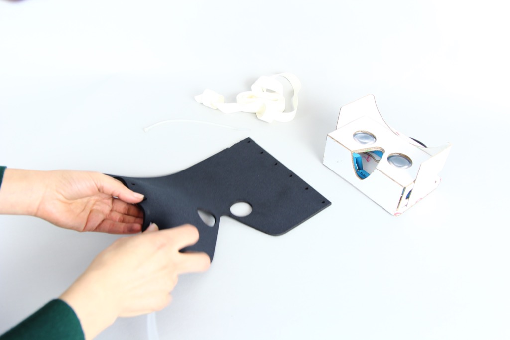
1Make a comfortable, light blocking mask for the Google Cardboard
In our testing we found that the standard Google Cardboard design lets in too much light, and is a poor fit for many different shapes of nose and forehead.
To solve this, we created this optional add-on. Just print out this file as a template for cutting neoprene or foam with a pair of scissors. We do not recommend using a laser cutter as this can be a health-hazard if you select the wrong materials!
![]()
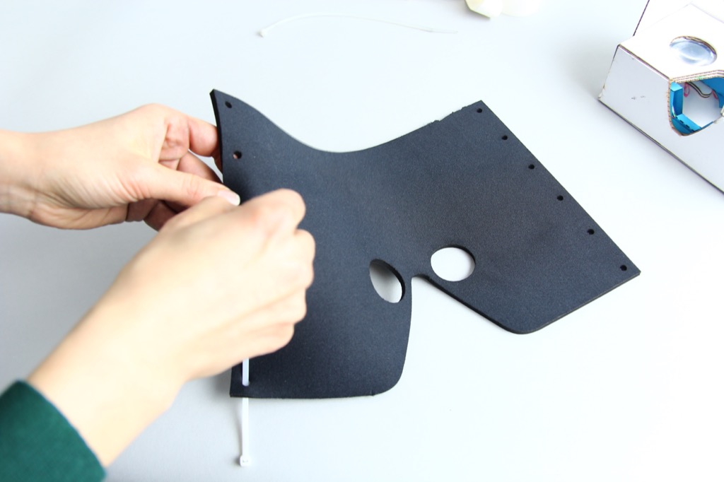
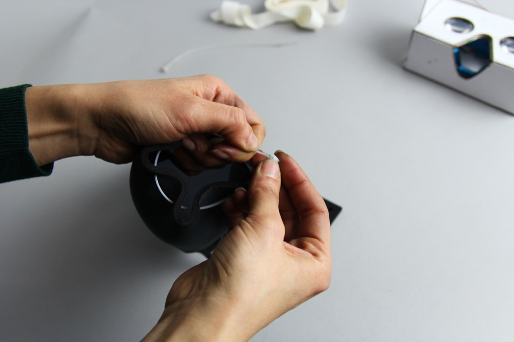
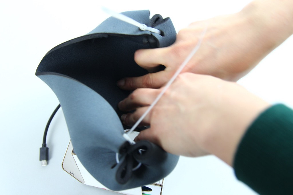
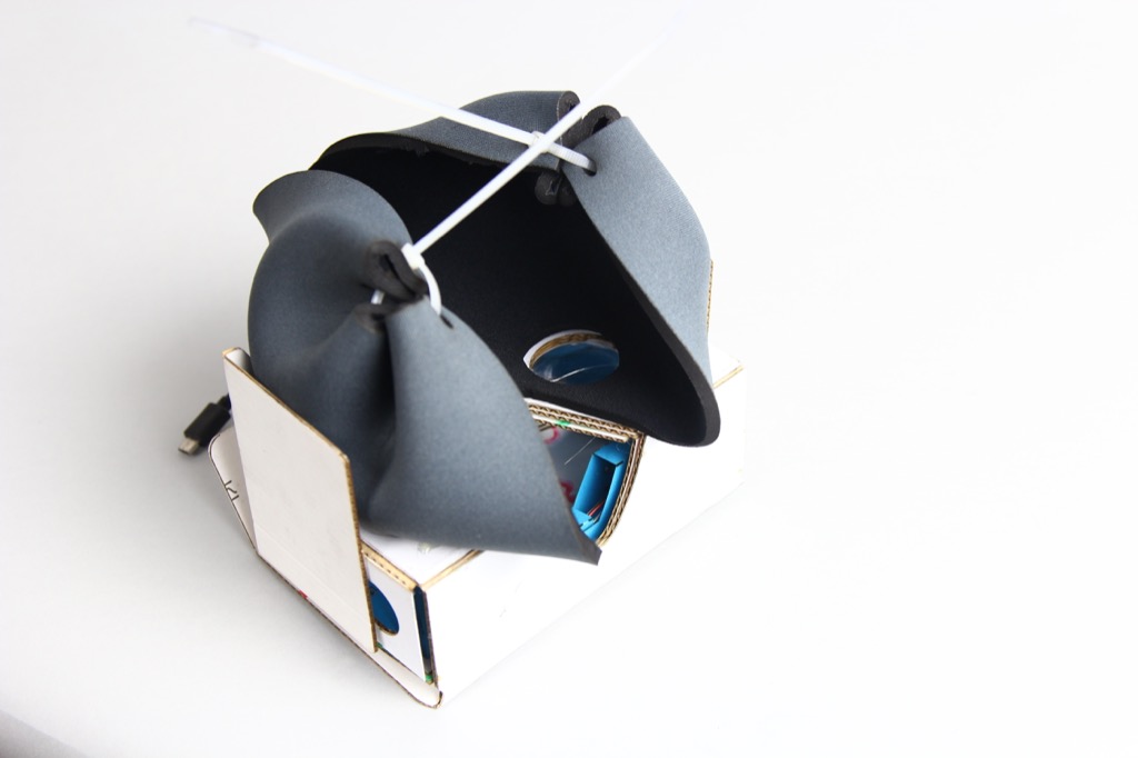
Next, take a simple clip-tie and thread it through the holes as though you were sewing...
![]()
Don't pull it too tight. The tighter you pull it, the more extreme the shape will become...
![]()
![]()
-
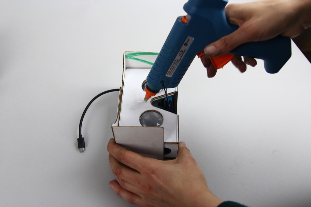
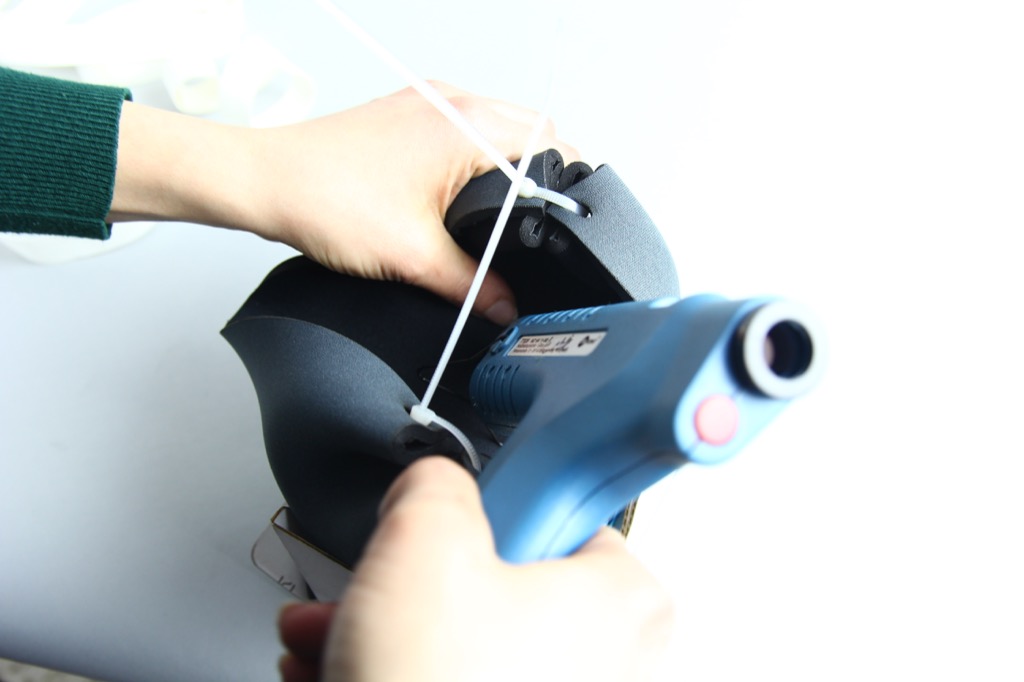
2Fix the mask to the headset...
Grab a glue-gun and just press the shape into position...
![]()
![]()
![]()
Great!
-
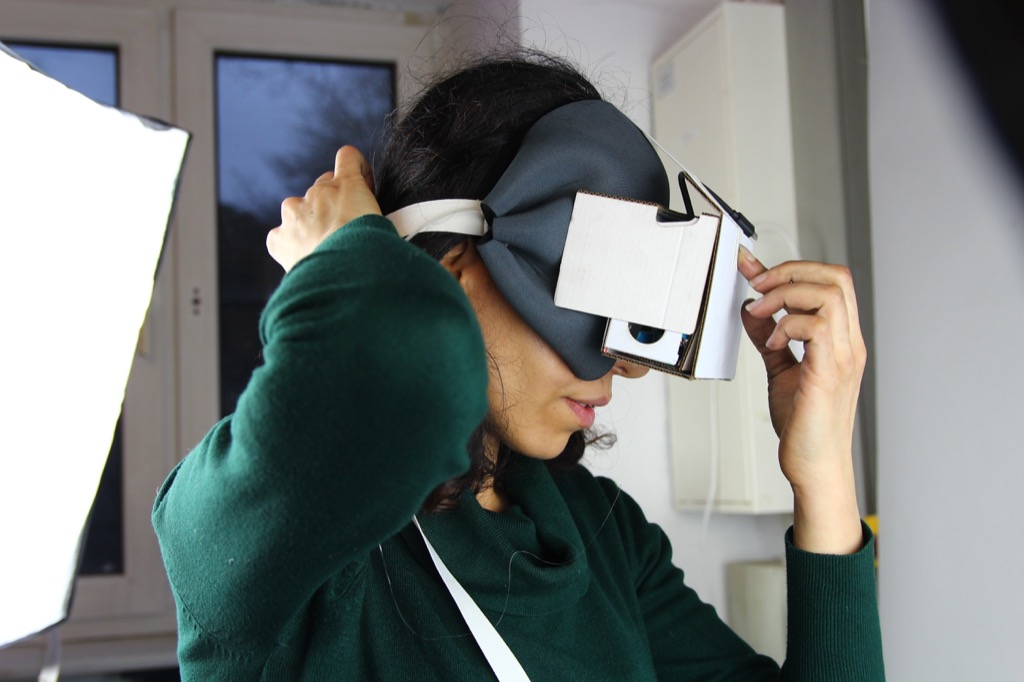
3Optionally, add some straps to hold it tight...
If you like, you can glue some extra head straps to hold the headset in place...
![]()
Use whatever straps you can find, that fit your needs/headsize...
![]()
![]()
![]()
-
4Now let's get the electronics ready...
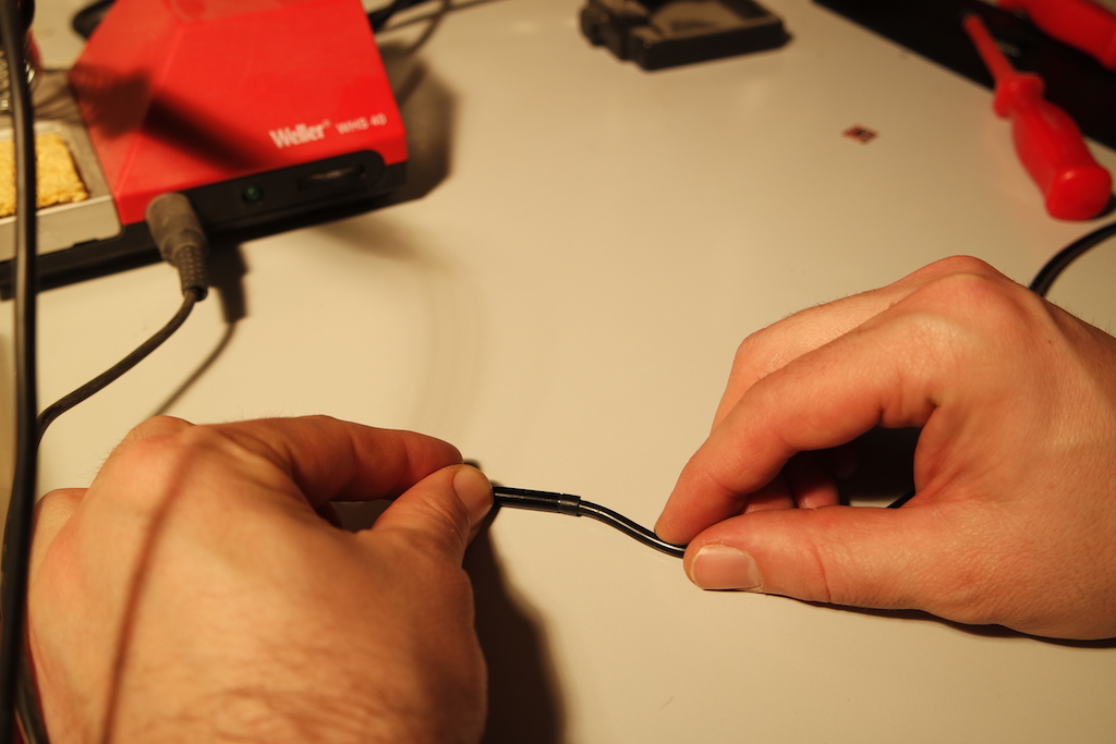
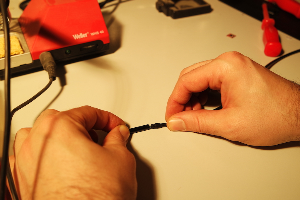
To keep things affordable, we use simple endoscopic cameras which you can find for around $6. First, you need to get the camera out of the casing. In these more modern (water proof) designs, you can simply "wobble" the cable at the end of casing to break the glue joint holding the casing onto the cable.
![]()
![]()
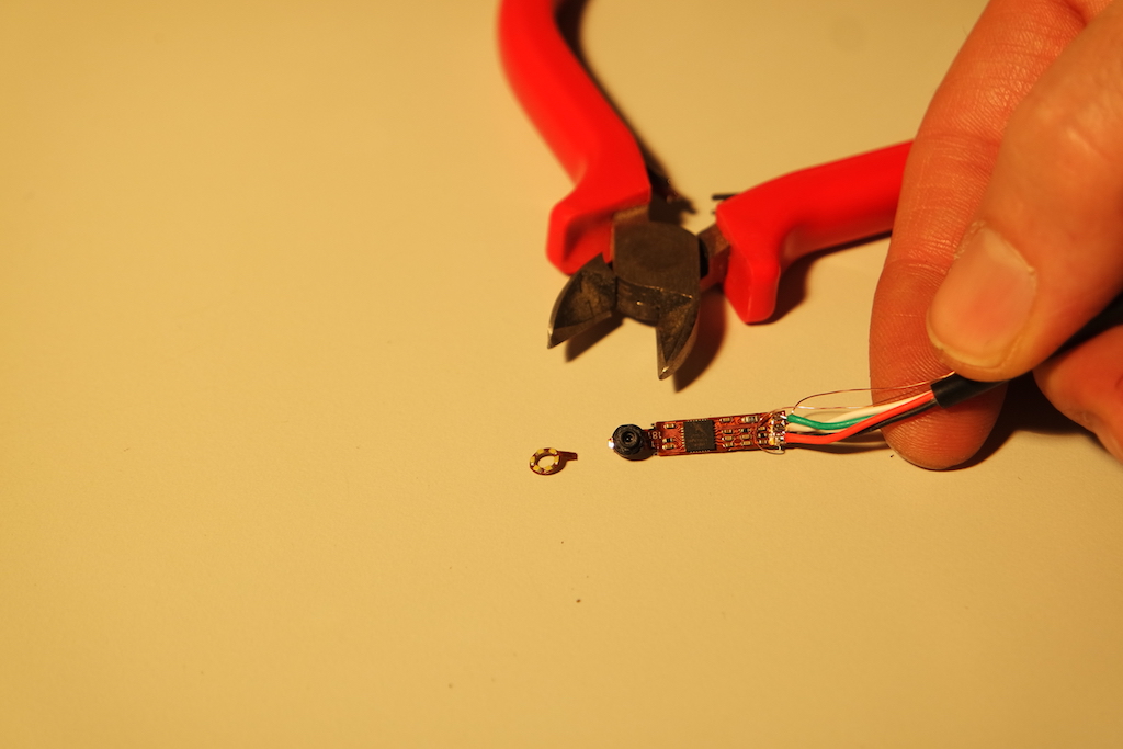
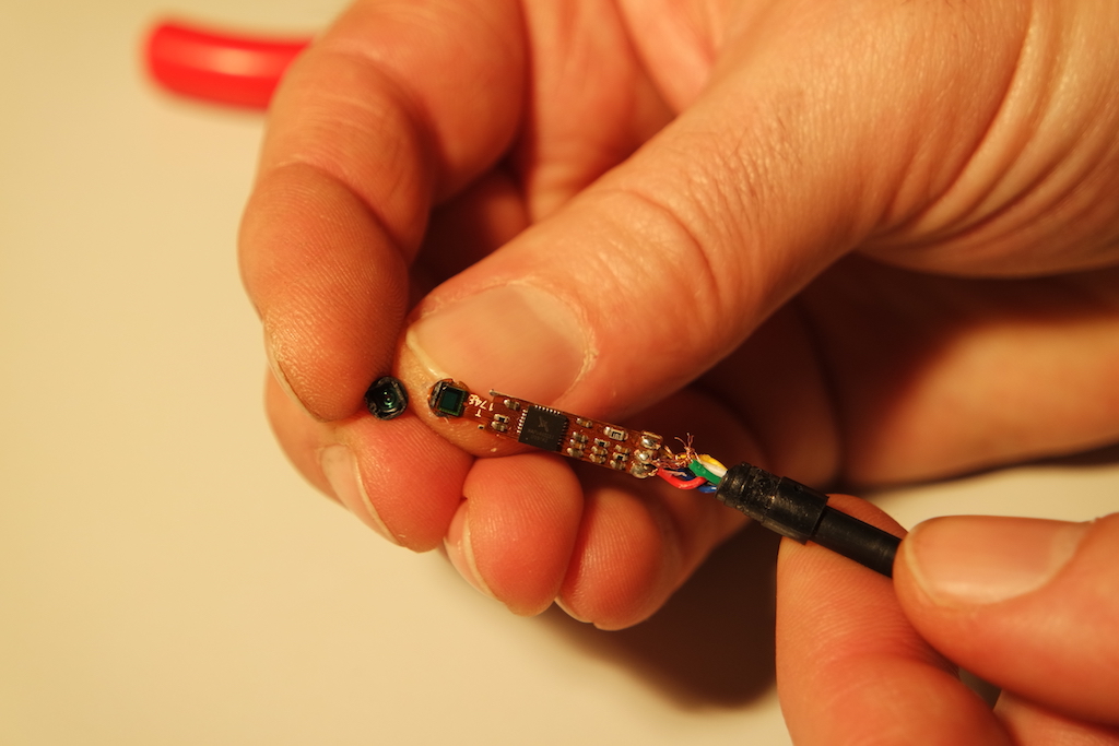
You'll then be able to carefully slide out the camera and the attached PCB.
![]()
![]()
-
5Now lets modify the electronics...
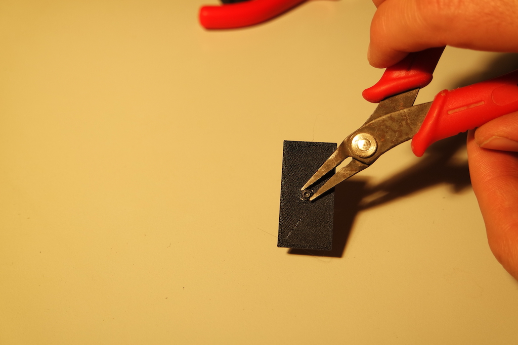
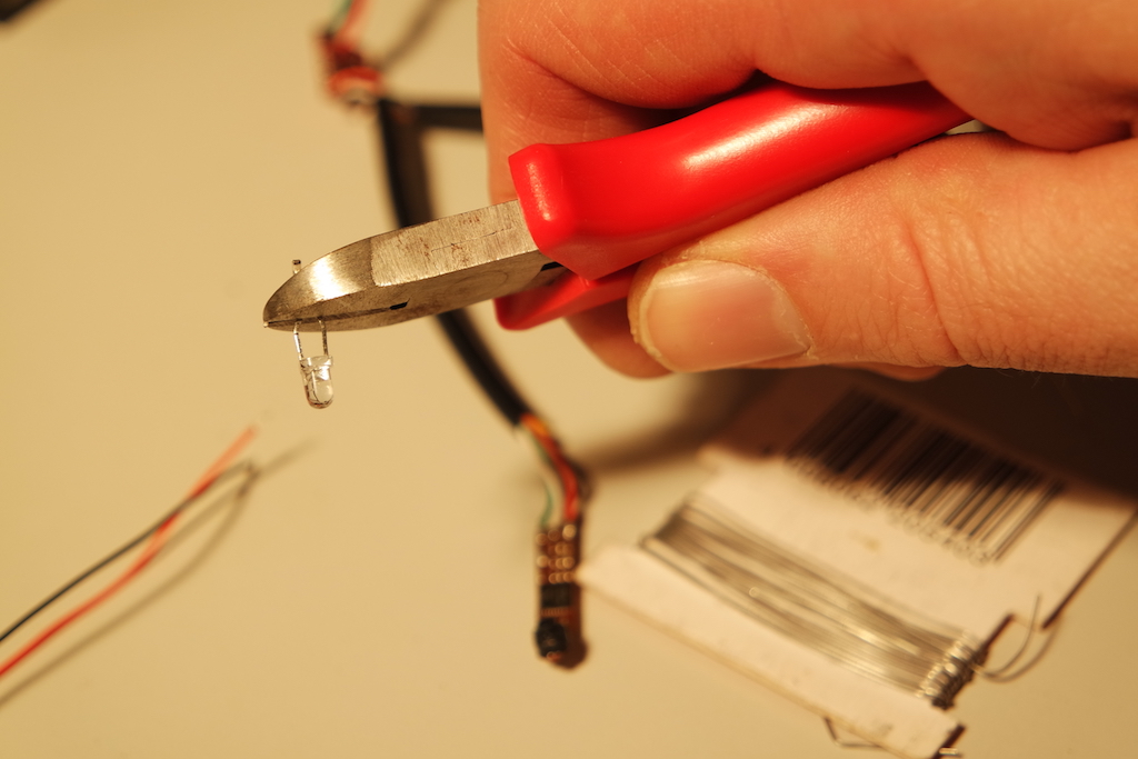
The endoscopic cameras come with a tiny ring of LEDs. These will be replaced later by an Infra Red (IR) light source. Simply clip off the LED ring.
![]()
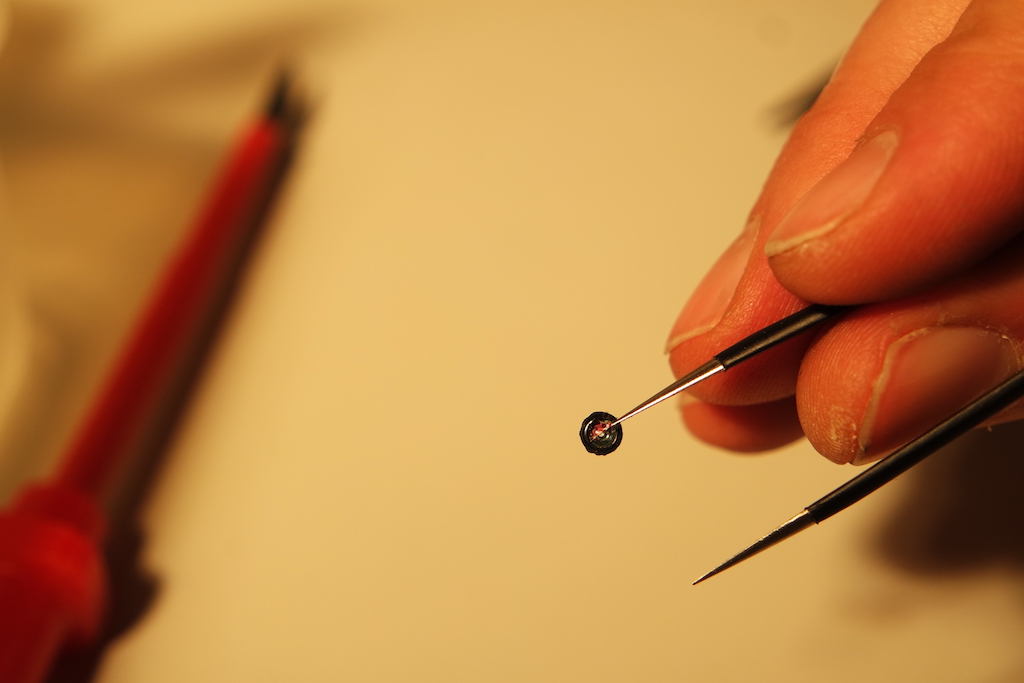
Next, we need to unscrew the lens on the camera so that we can remove the IR filter. Why? IR light isn't seen by the human eye, which makes it great for illuminating the pupil without distracting the user. However, these cameras (almost all cameras) have an inbuilt IR filter which blocks infra-red light, so it needs to go!
To remove the filter, we use the handy 3D printed aide you can get here
![]()
![]()
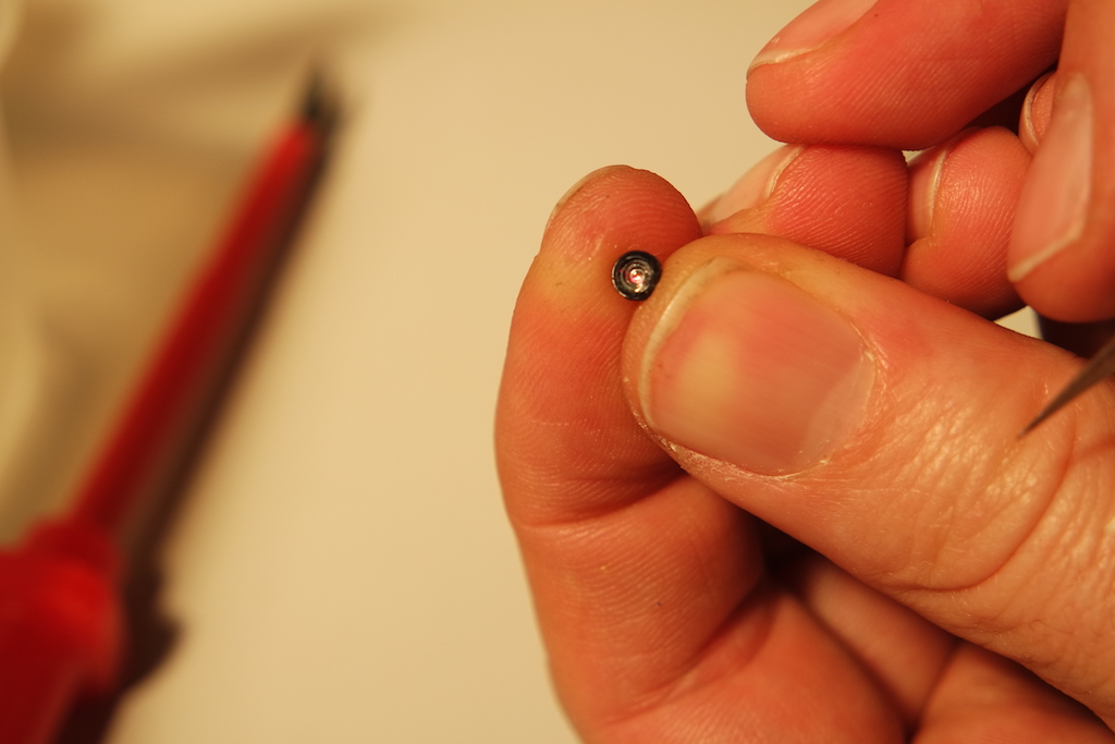
Now comes the hard part. You need to smash out the filter. Just poke it until it breaks and take out the pieces. More elegant suggestions are welcome ;-)
![]()
![]()
Make sure you clean the lens before continuing...
![]()
-
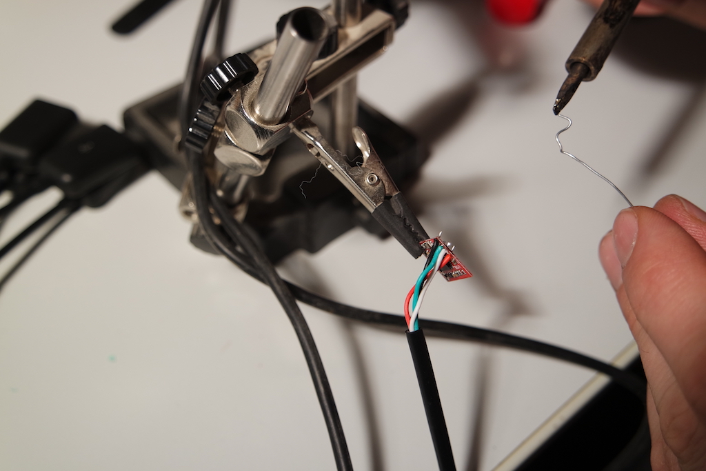
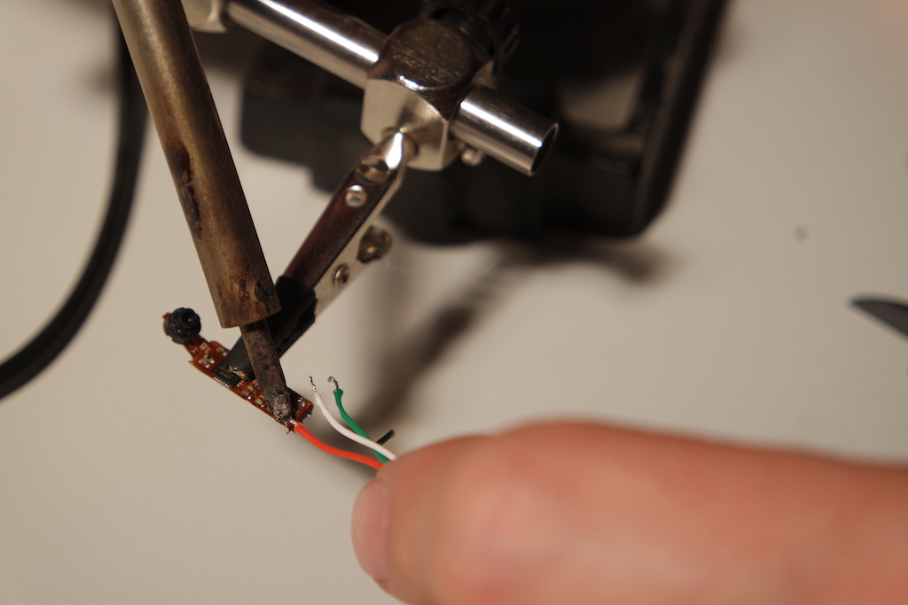
6Now lets get soldering...
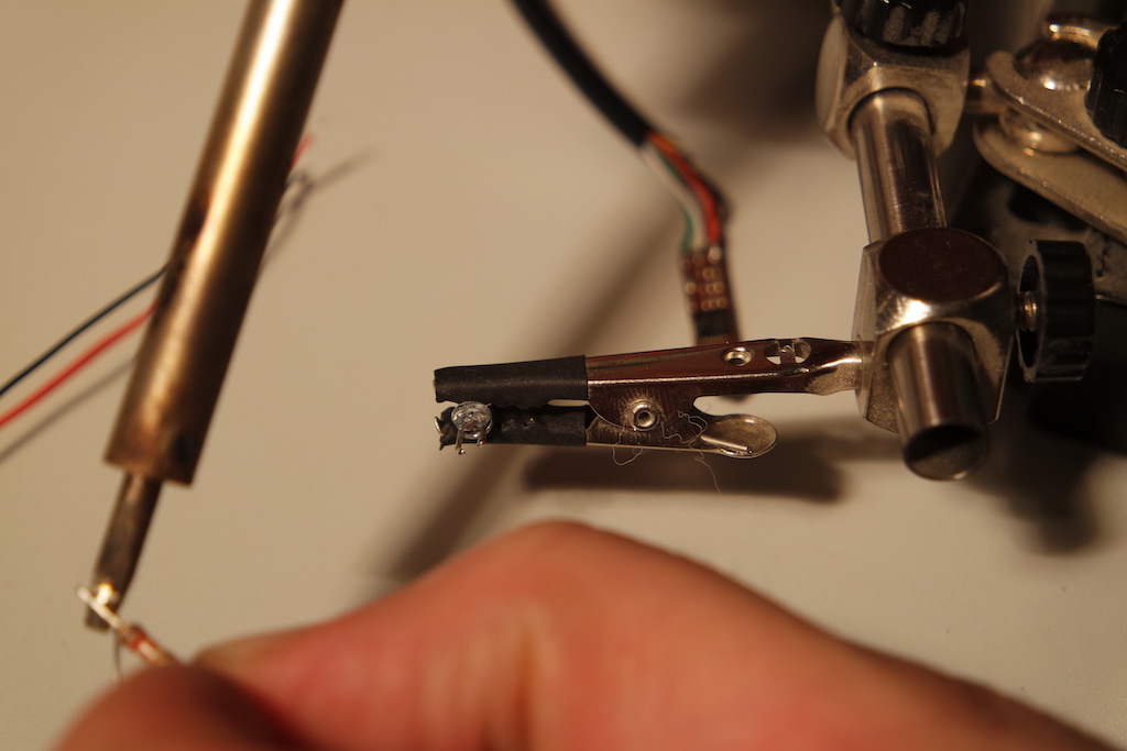
Now we can use the power supply to the LED array to power an IR LED. Make sure you calculate the right resistor value for your choice of IR LED. Infra-red can be harmful for the eye! This is a good source of information for your calculations.
![]()
![]()
![]()
![]()
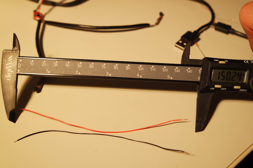
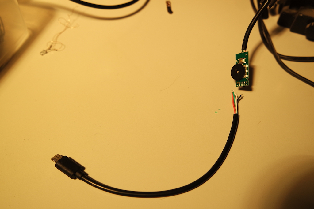
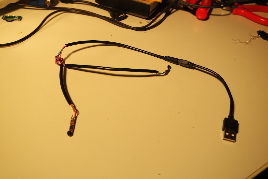
You can reuse the usb cable. The larger "illumination dial" at the main USB connector is superfluous. The chip controlling image processing and USB transfer is the one right next to the camera!
![]()
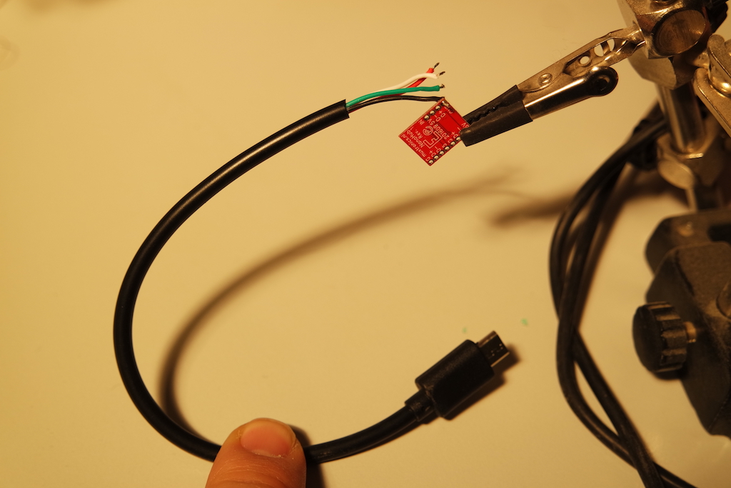
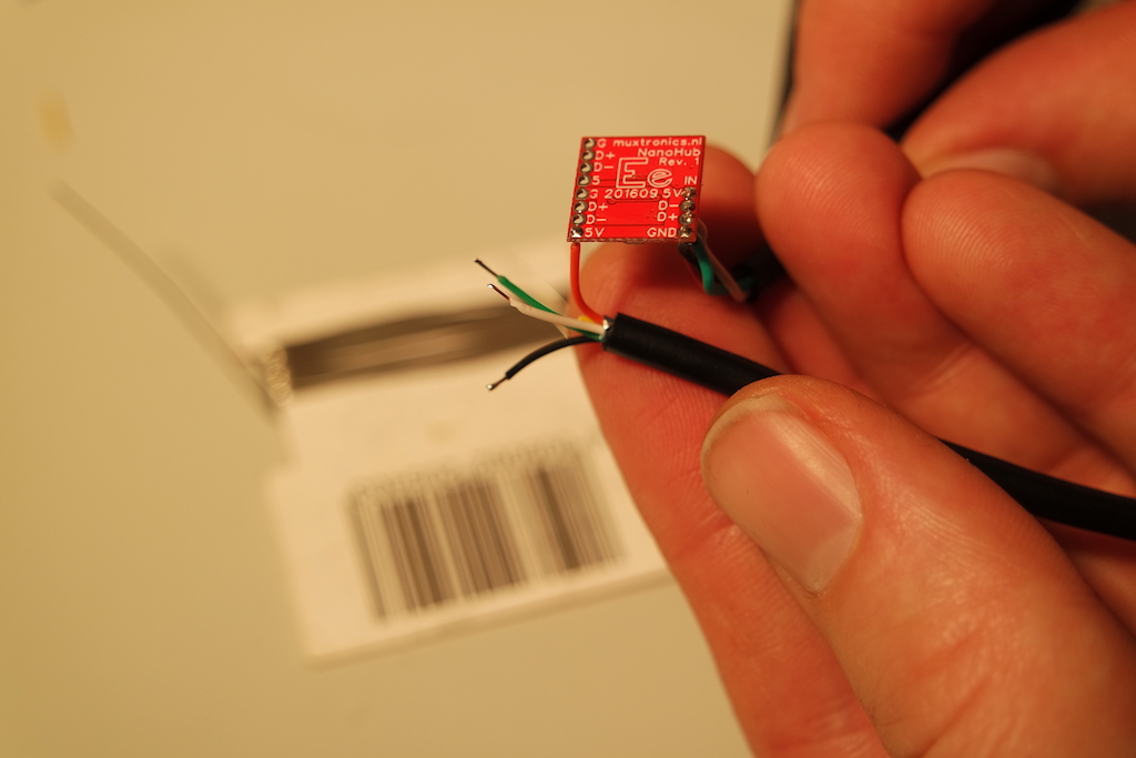
Solder this up to the nano usb hub of your choice. In this case theNanoHub from Berkel en Rodenrijs!
![]()
![]()
![]()
![]()
![]()
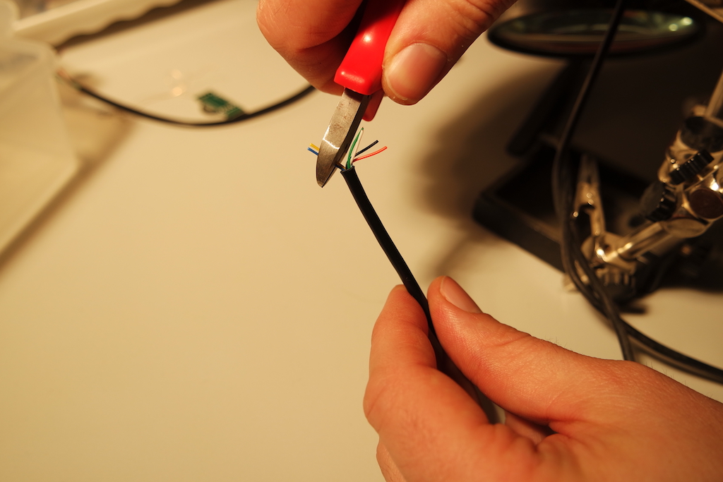
You'll do this again for the two cables which connect to the cameras. They need to connect to the camera PCB and also the nano hub.
![]()
![]()
![]()
![]()
![]()
![]()
![]()
![]()
![]()
-
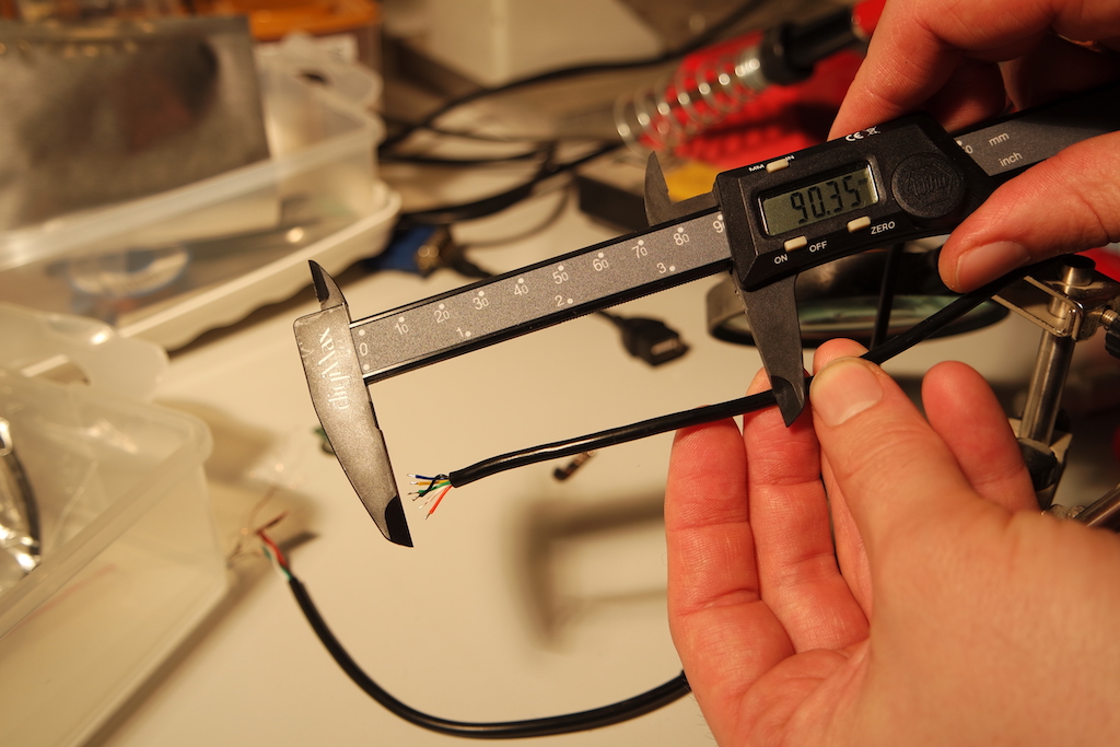
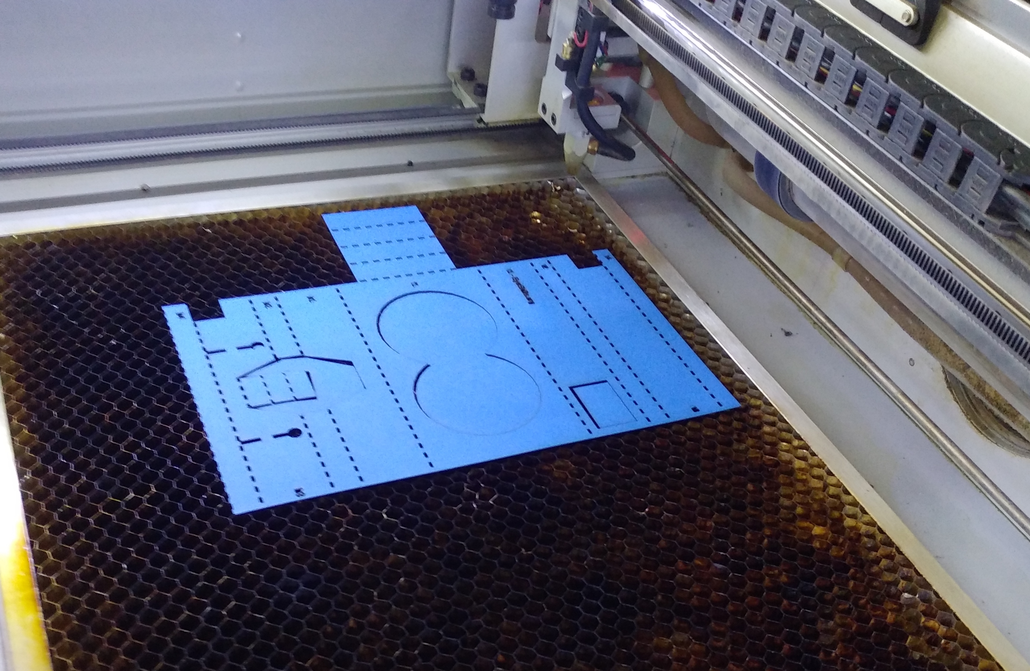
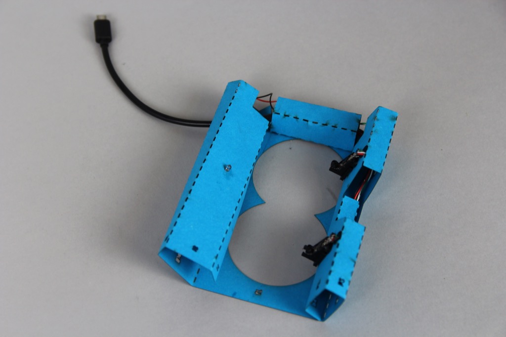
7Now lets cut and fold the core to mount these parts...
Laser cut this file. You can print this out and cut along the lines with a knife, or feed it into a laser cutter. We recommend using 2mm stiff card.
![]()
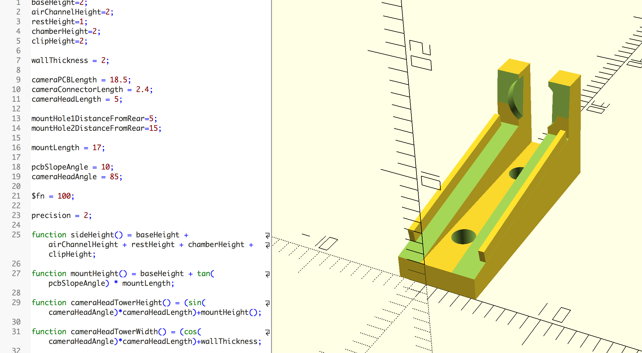
If you wish to 3D print the camera mounts, you can download the OpenSCAD files here. Printing with PLA filament is fine.
![]()
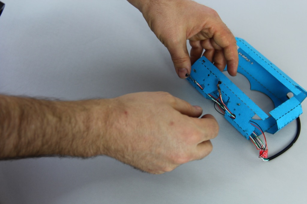
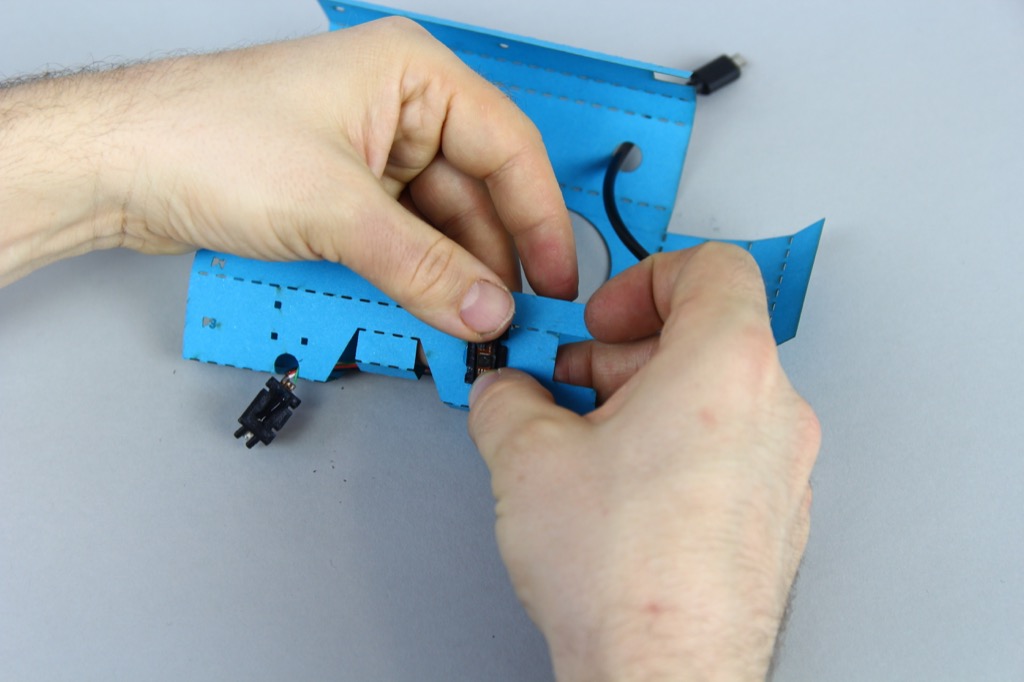
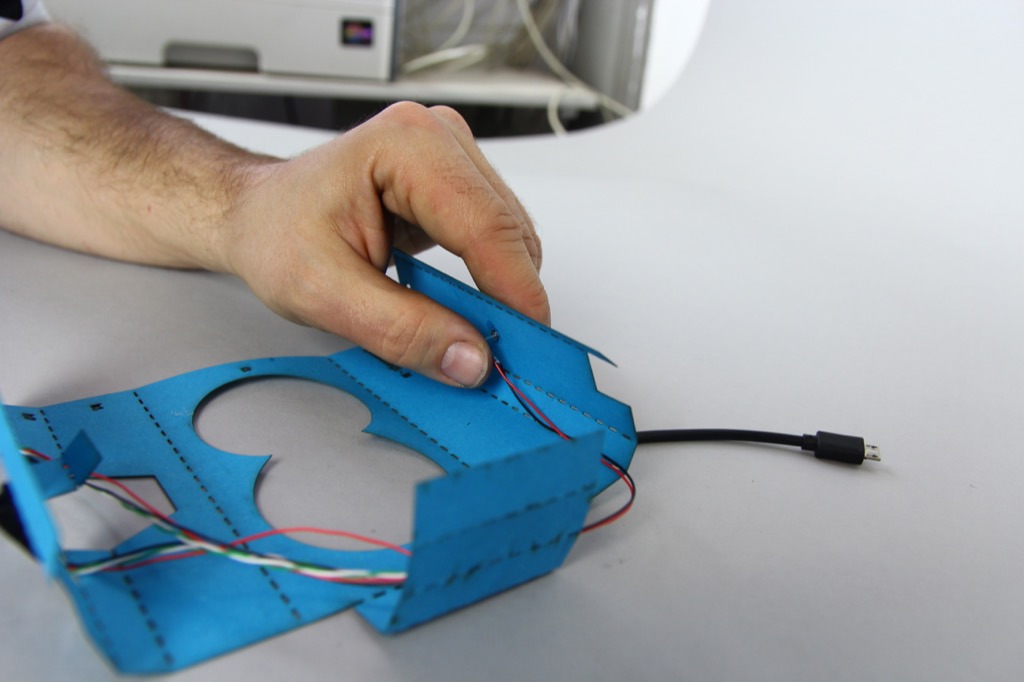
After you have assembled the electronics you will need to feed them into the cardboard core.
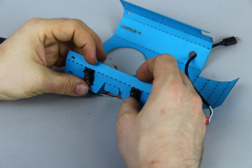
First, feed the camera PCB and lens units through the feed holes at the front of the core (b3).
![]()
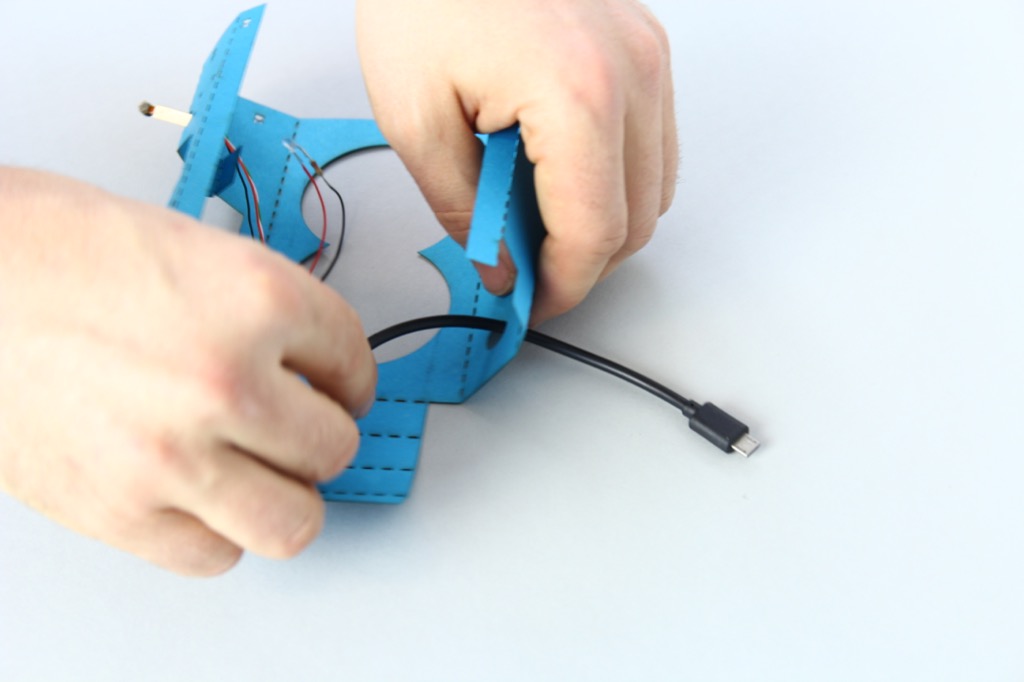
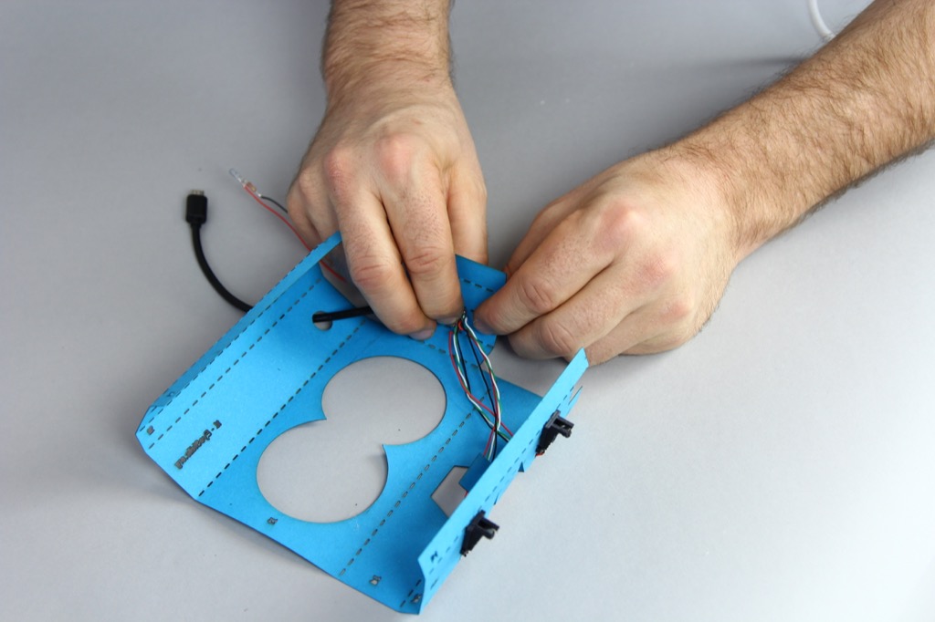
Next, feed the USB plug through the output hole at the top of the core (t1).
![]()
![]()
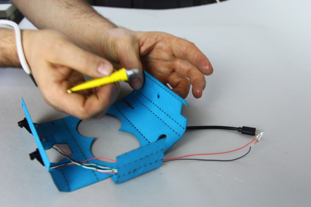
Now glue along the edges of the camera holders (leaving space for the heat to dissipate along the central channel)...
![]()
![]()
... and mount the camera lens and pcb unit into the appropriate slots on the camera holder.
![]()
![]()
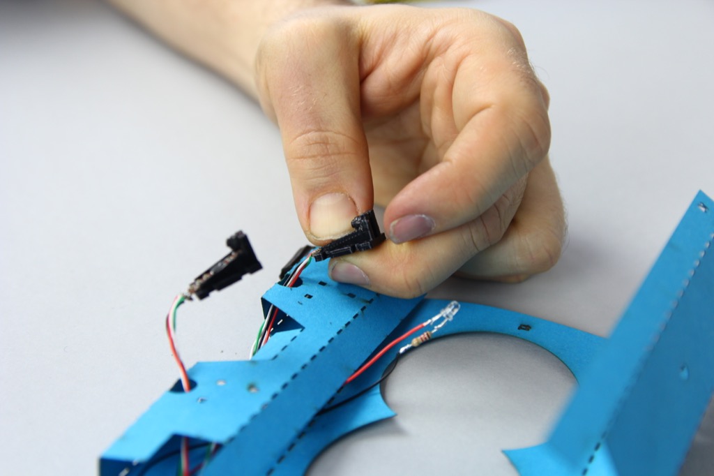
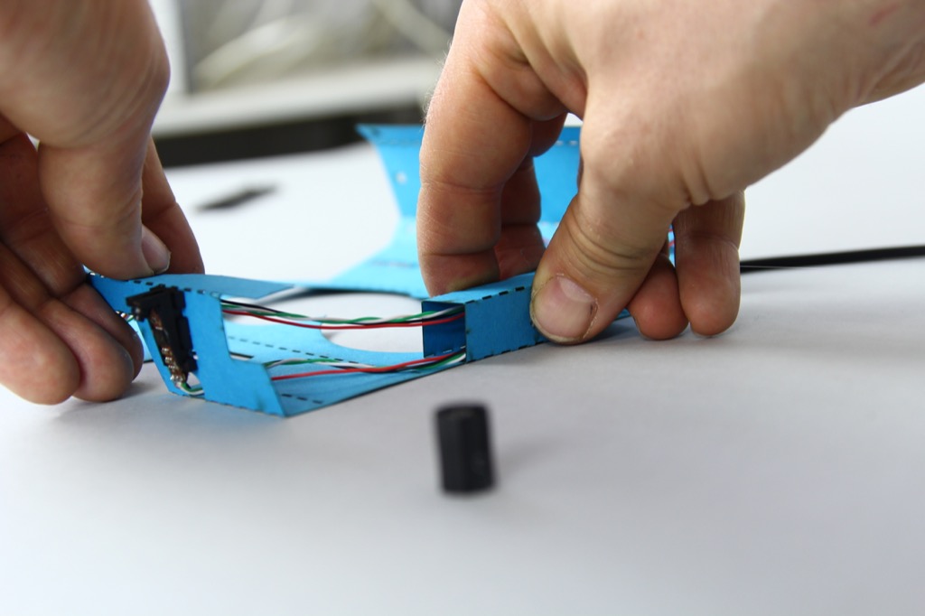
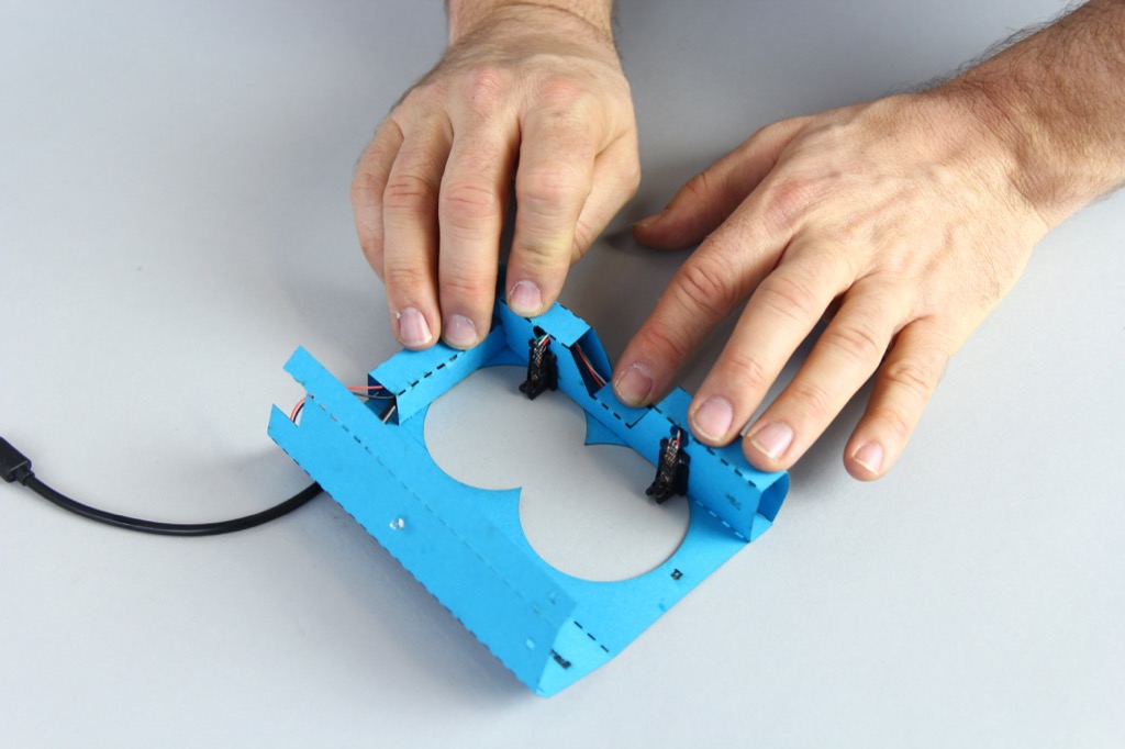
Once you have both cameras in position, you can mount the camera mounts on the core itself. Use the installation assistant to ensure that the module are mounted facing in the right direction and also in just the right position.
![]()
![]()
![]()
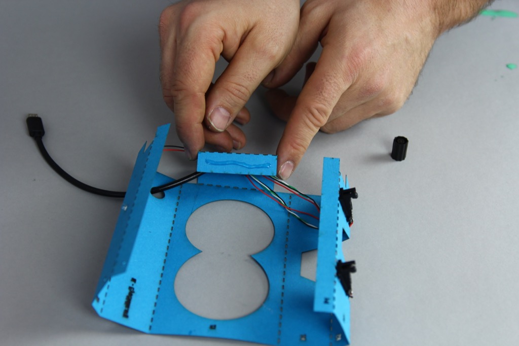
Next we're going to glue the nano-hub into position in the cabel channel that runs between the bottom and top of the core.
![]()
![]()
After that, we will afix the Infra Red LED at the top of the core which illuminates the eyes.
![]()
![]()
![]()
-
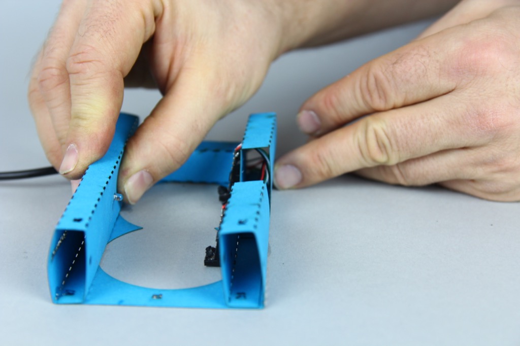
8Time to glue it all together!
First, glue and fold the cable channel which holds the usb hub.
![]()
![]()
Next, glue and fold the "nose guard" around the cable coming from the left most camera.
![]()
After this, you can glue and fold the rest of the base unit...
![]()
Now you just need to glue and fold the upper-most section.
![]()
![]()
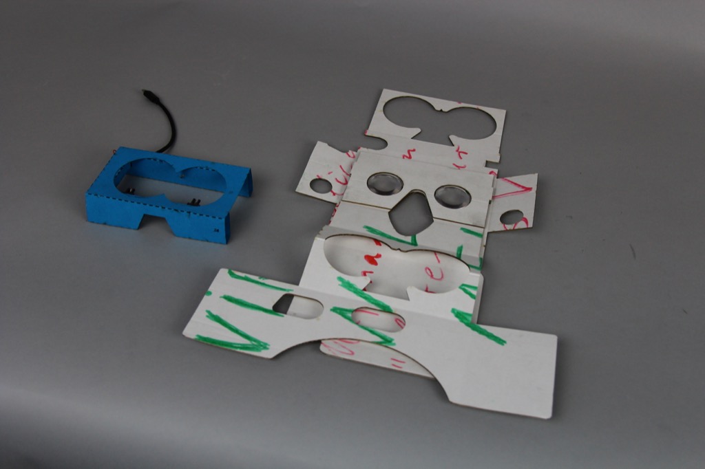
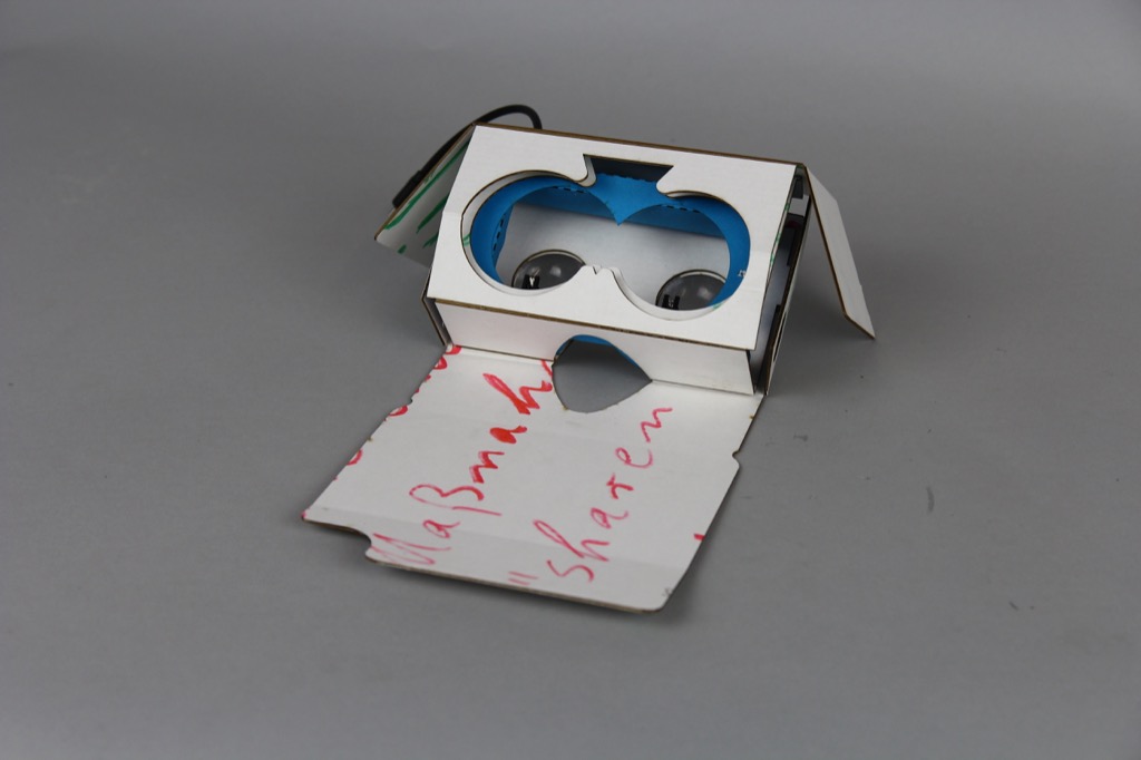
Now you are ready to place it inside the unfolded Google Cardboard V2, and fold it in.
![]()
![]()
As you may have noticed, there are several areas which could be improved. The core needs sides to glue the surrounding cardboard against, and the IR LED positioning will probably need to be rethought. It may also be desirable to add additional tabs to improve the structural firmness between the top, bottom and cable channel. Feel free to adapt the OpenSCAD design and send us an updated copy! :-)
EyeTracktive - Eye Tracking for Google Cardboard
An ultra-low-cost eye-tracking insert for Google Cardboard V2! Unleash the power of the eyeballs!


Discussions
Become a Hackaday.io Member
Create an account to leave a comment. Already have an account? Log In.