Scott Swaaley
-
Assumptions are like butt cracks ...
07/02/2019 at 21:56 • 0 comments... everyone has them and they really could use a good wiping now and then.
The more we talk to potential consumer customers, the more they forward us to their friends that have industrial or light manufacturing shops. The more we talk to those folks, the questions we get about a three-phase solution. We spent the first few conversations thinking "No - silly - our device is for little grinders, not huge industrial machinery."
But then, something magical happened - we remembered that we were presumptive idiots and began to test some of our assumptions. It turns out that there is this whole world of relatively small three-phase bench grinders like this Dayton model or this Jet model. Now why on earth would you make a fractional horsepower grinder compatible with 3-phase 480V service!? It draws only 1.1 amps at that voltage!
While we haven't answered that particular question yet, it has become very apparent that these small industrial three-phase grinders need love more than the single-phase consumer models we had originally targeted. We therefore have an announcement ...
Grinder Minder is now Poly-
AmorousPhase and is Going IndustrialAnd as luck would have it, this makes our job easier, for two main reasons. First, poly-phase circuits draw less current per phase so we can downsize our electronics even further. Second, poly-phase motors don't have start capacitors, run capacitors, or centrifugal switches ( >2 phases = directional starting torque) so we don't have to mess with the impact of those variables or worry about capacitor fatigue. All in all ... we're golden.
This is a mind-shift for us so we're going to go back to the drawing board to - you guessed it - validate the assumptions we made when designing as a consumer device. Once we identify some new hardware we'll back with more news. We did find this beautiful honey though ...
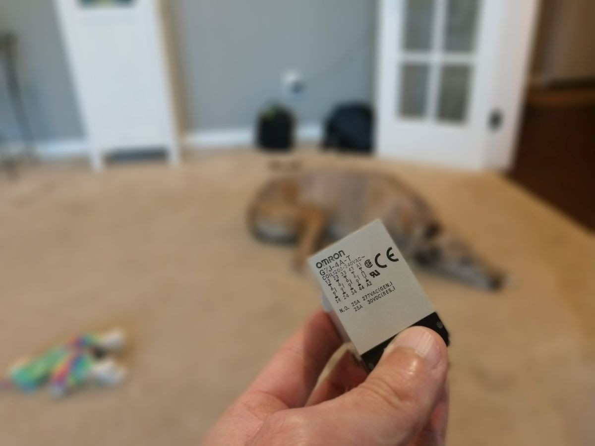
![]()
And no - not the sleepy greyhound - the compact, 4 pole, PCB-mountable, UL508 Recognized, 5HP capable relay. I think I'm in love.
-
Wait...who are we doing this for again?
06/24/2019 at 16:52 • 1 commentIf there's one thing we like almost as much as making, building and braking, it's sharing what we're doing with others. For the most part, people like to hear about something different from their day to day trade, and listen in. But as anyone in this community knows, it's always more fun to share a project with someone who is -REALLY- into what you're doing. Not for the focus and interest (though that's always awesome) but more for the insight they can provide. And lately, we've heard the same message from a few of these folks. First, what we're doing is very awesome -- it seems a lot of people in the industry of heavy power tools are highly aware of the dangers, and know a friend who was injured when safety measures weren't observed, or when they weren't enough. The second message these folks shared was that our target market is off base. According to these folks, the biggest need for tool safety is not in the at-home market, but instead in the bigger, more powerful tools which require 3-phase power.
When we started out, we made assumptions about our customer and target market. Now we're seeing real data which contradicts our assumption, and we have a decision to make: Do we trust our starting impression of the market, or do we jump in on some customer research? Given our timetable and our goals (and the spirit of the product development competition we're in) we think customer research is going lead to the best outcome. So what's next? We're going to sit down with some more people and try to answer the question "Who would see the most value in a tool braking solution?". Updates to come...
-
Two steps forward, one step burnt.
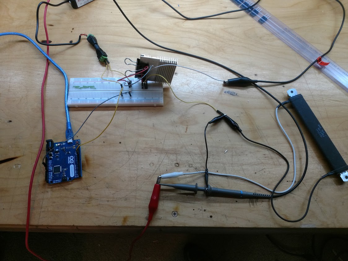
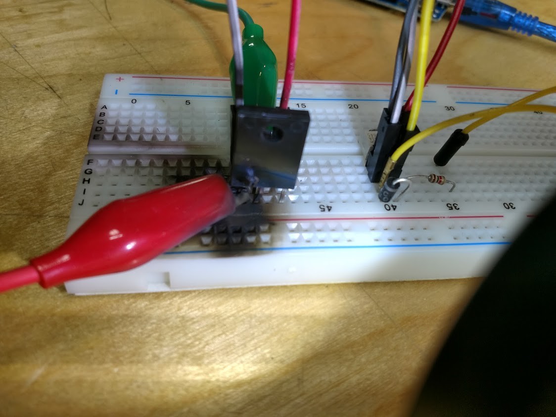
06/02/2019 at 04:45 • 0 commentsToday was all focused on testing out the braking effects of a pulsed rectified sine wave on a motor. But to do such a test, we needed a circuit which would be able to switch fully rectified mains at a frequency several times higher than 60Hz. Our first circuit was composed of a power MOSFET for switching the power on and off, a bridge rectifier to give us a full wave rectification of AC power, an Arduino to give us a cheap and easily configured square wave, and an optocoupler to protect the Arduino from accidents. We used a bar-style 50 ohm resistor for the load to just start testing, to be replaced with the grinder once the circuit was doing the basics correctly.
![]()
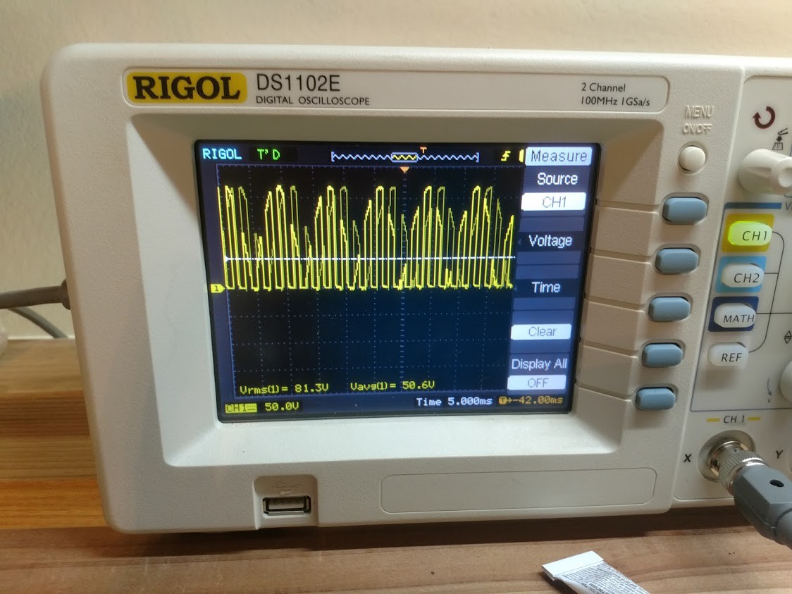
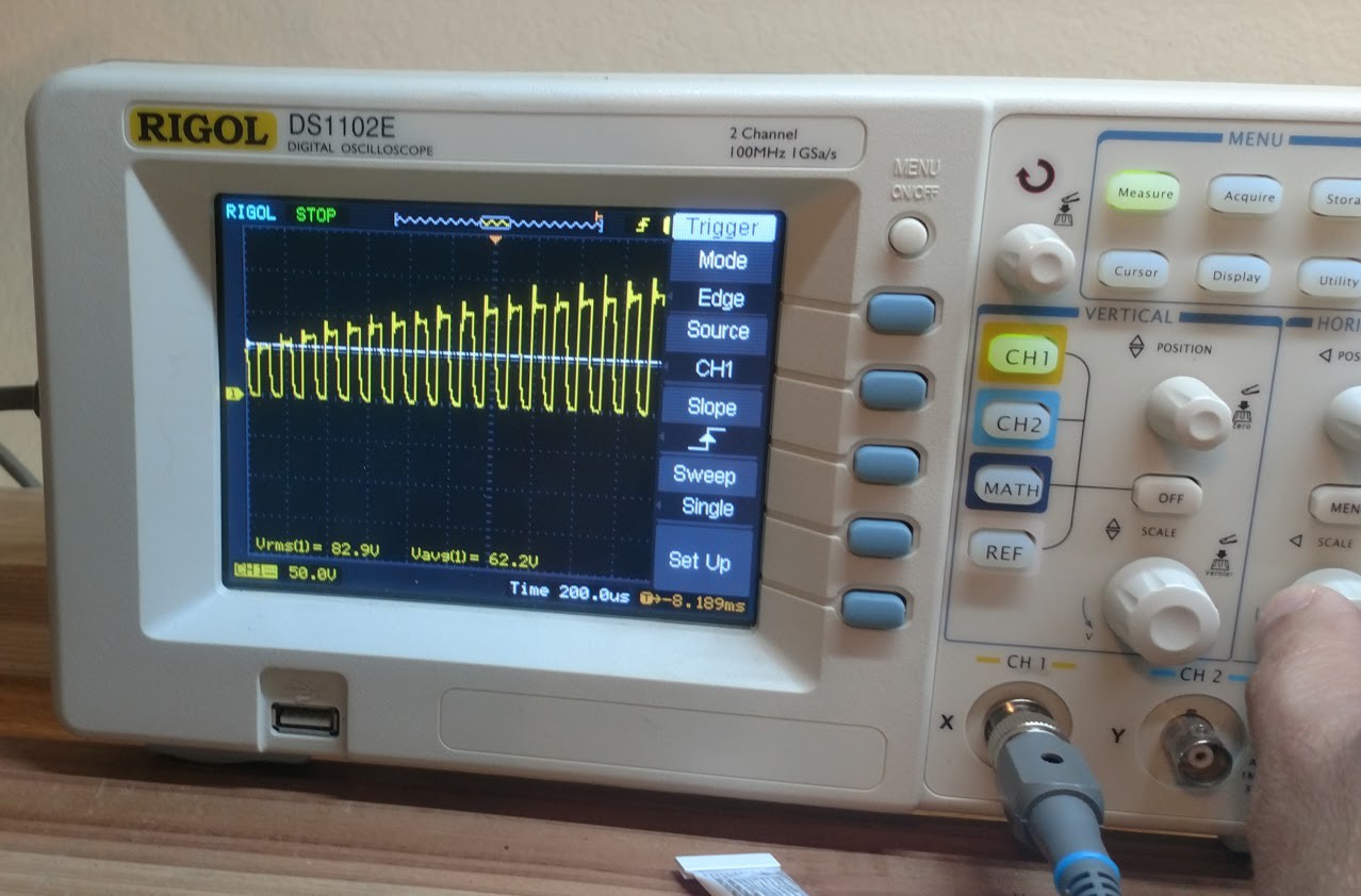
We configured the Arduino to produce a roughly 500Hz square wave with 50% duty cycle, and kicked on the power. Our first test went off without issue, producing a very nicely chopped up sine wave, and a little heat from the resistor.
![]()
We wanted our later motor tests to have a wider envelope in terms of tested frequencies (upwards of 5kHz), so we configured the arduino to send out a faster signal. At this point, we just started seeing the fully rectified wave from the rectifier. We tested to ensure the optocoupler hadn't failed closed, and found no fault. Then we double checked it's timing limitations. Unfortunately, the time to turn on was ~10μs, while the time to turn off was ~50μs, which gives us a frequency limitation of 1.6kHz. So, we thought hard about the actual need of the optocoupler, and decided to do without it.
![]()
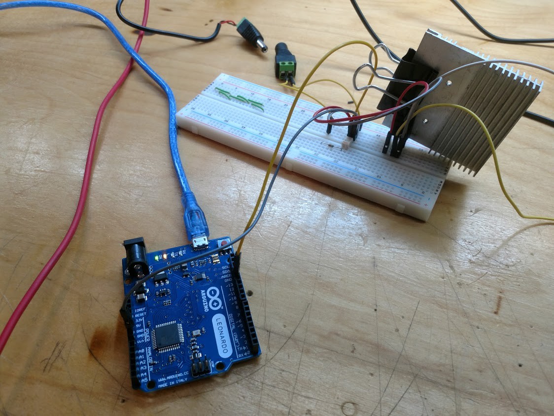
Having bypassed the optocoupler, we ran the test again, and sure enough, we landed a very nice higher frequency chopping of the sine wave.
![]()
With our basic test completed, it was time to hook up the Grinder and see what happened.
It actually worked quite nicely, altogether. Sure, we had a lot of inductive kickback whenever we turned the MOSFET back off, and the flywheel diode we had got a little toasty from dropping that current on it's return trip, but altogether, it was at step in the right direction. This is where we started having a few issues.
![]()
To start, our flywheel diode broke down from heat on the second test. We were treated to some arcing and charred breadboard before we shut it back down. We found that the diode, the mosfet, and the Arduino were shot (Blew the cap right off the FTDI chip). We replaced the smoked parts, went to a larger protection diode, added a optocoupler with a faster response time, and directly soldered the connections to the pins of the MOSFET.
![]()
Again ready to proceed, we kicked on the power, and immediately blew the MOSFET and charred the heck out of the pulldown resistor on the MOSFET gate. Whoops.
-
Motor Characterization
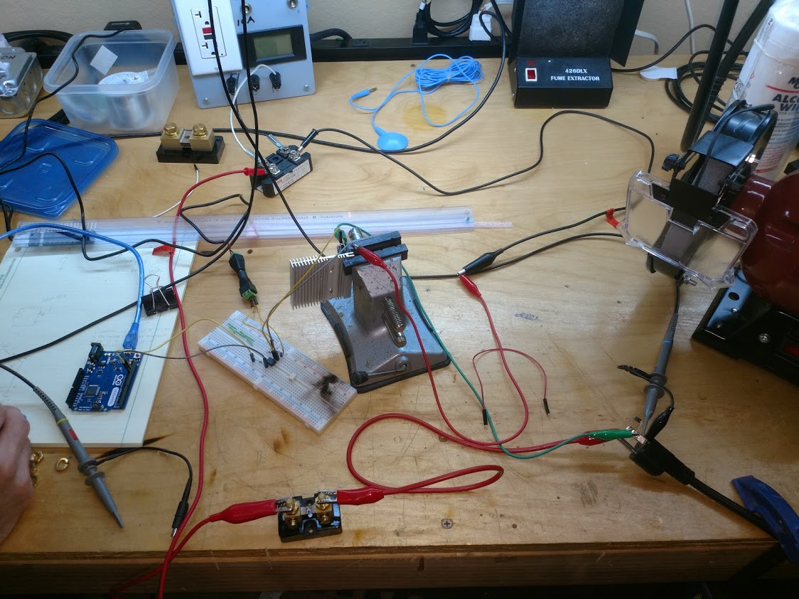
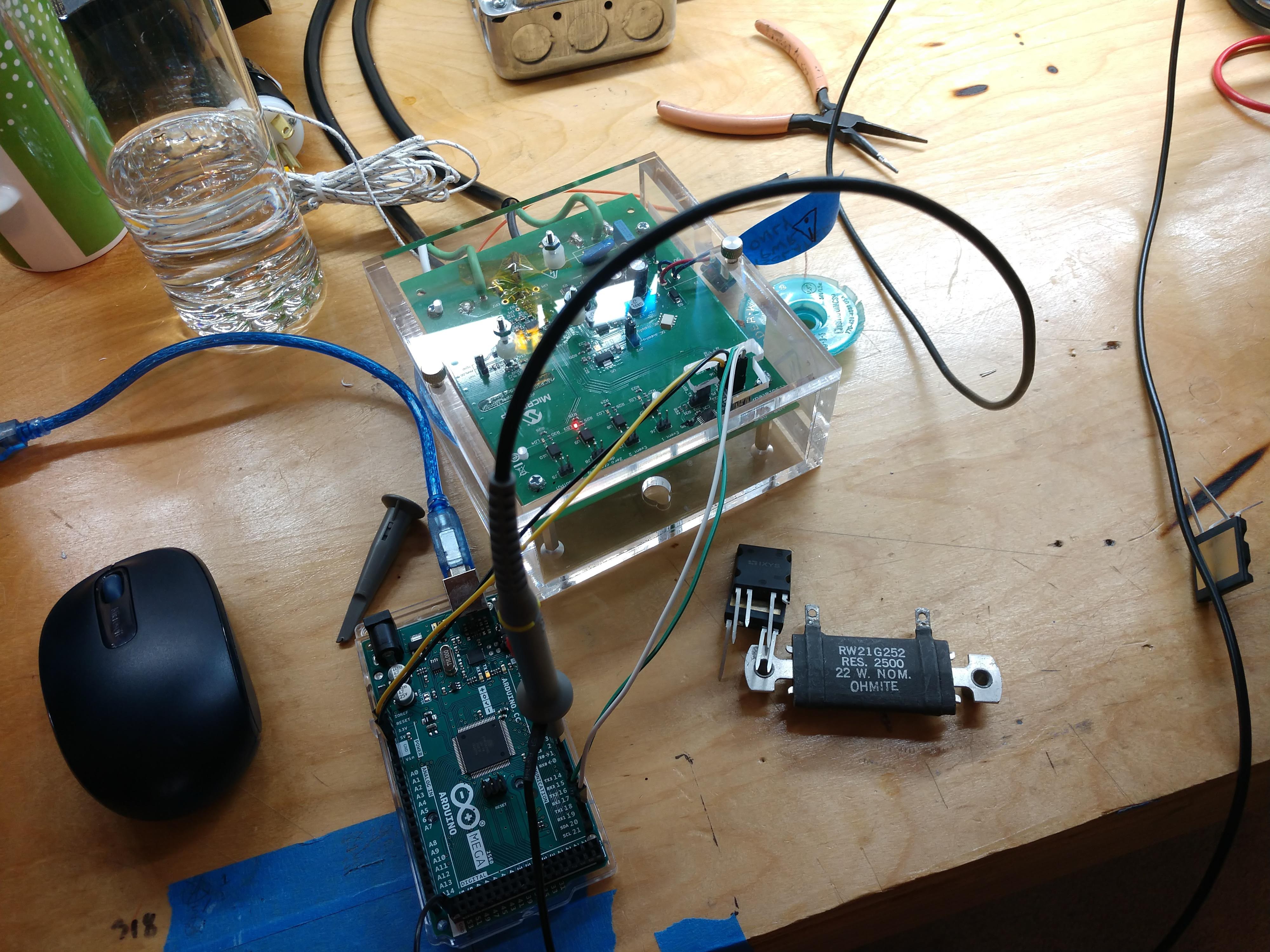
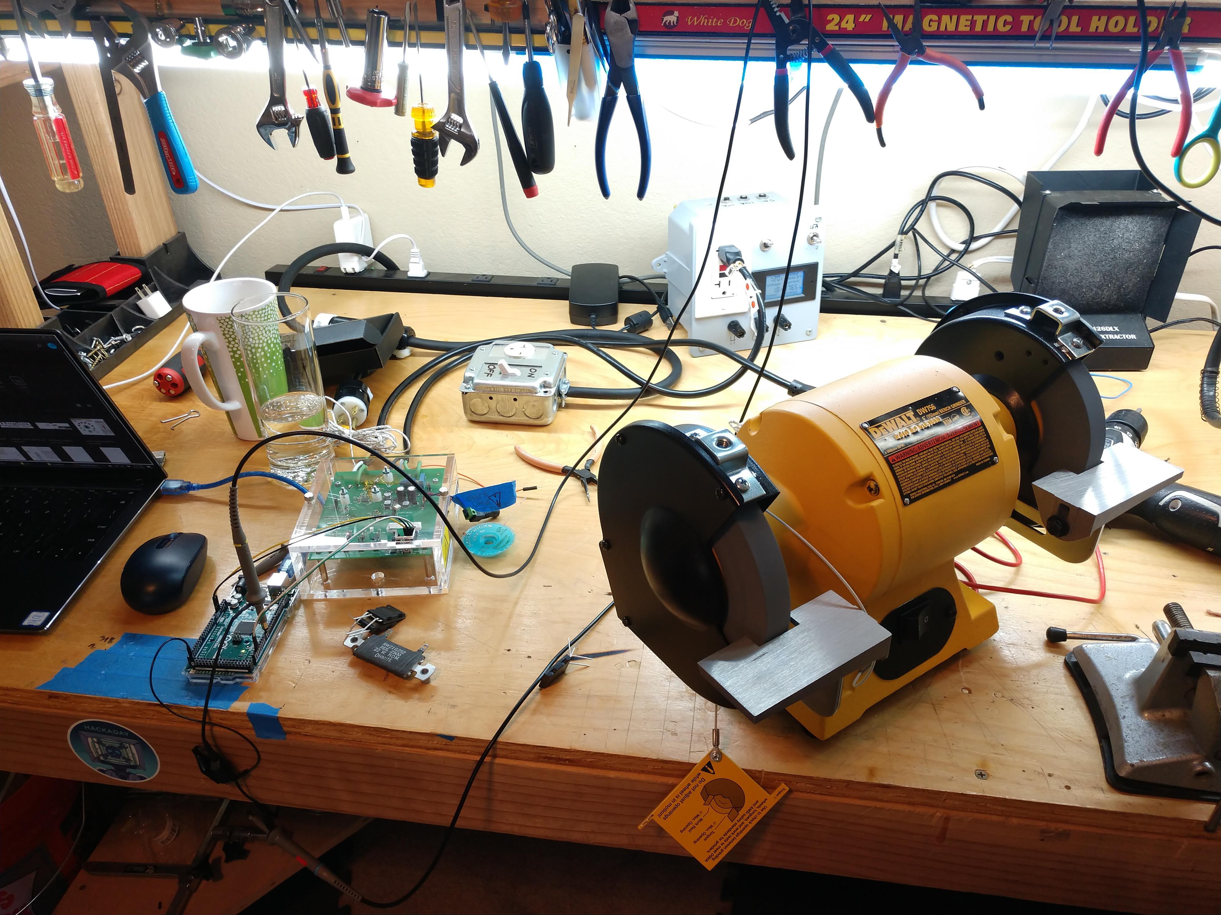
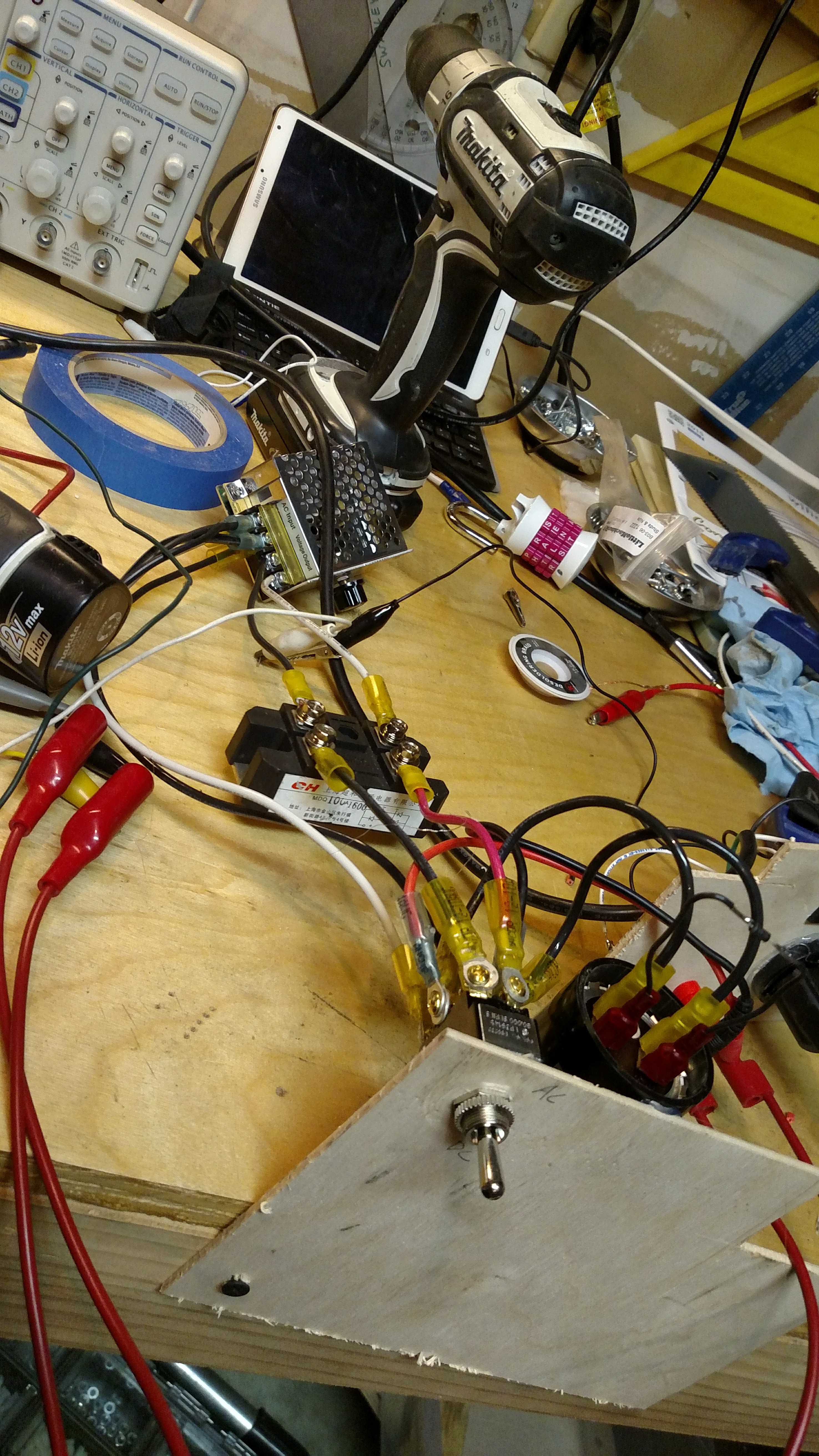
05/11/2019 at 19:26 • 0 commentsToday we spent some time characterizing the motor for a mid-size grinder. Specifically, a 5/8 HP DEWALT DW756 6-Inch Bench Grinder. I've been working with the eval board for the Microchip MCP39F511A Energy Monitor IC and finally tweaked my code enough to run it via an Arduino at an overall read-rate of about 50hz. I then use MegunoLink (which I highly recommend) for basic GUI and visualization. This is the test setup:
![]()
![]()
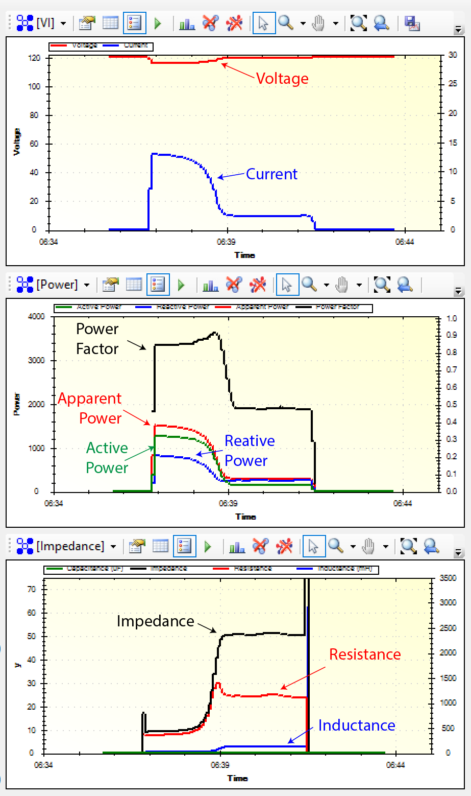
I was able to plot the startup and run characteristics of the motor and shared the plots below. Of note is the impact of mechanical load on the electrical characteristics. That's just one of the many things we need to characterize. Pretty cool plots. One thing doesn't look right though - can anybody spot it?
![]()
-
Specifying a DC Supply
05/10/2019 at 19:27 • 0 commentsNow that you understand the DC power requirements from our previous post, it's time to get into the details. Let's start by looking at the typical specs for an AC/DC supply (listed below). Now, we get to start crossing off ones we don't care about.
- Input Voltage (AC): 120VAC
- Max Output Voltage (DC): 90V
- Output Power: 5kW
Output CurrentEfficiencyLine RegulationLoad RegulationRipple & Noise
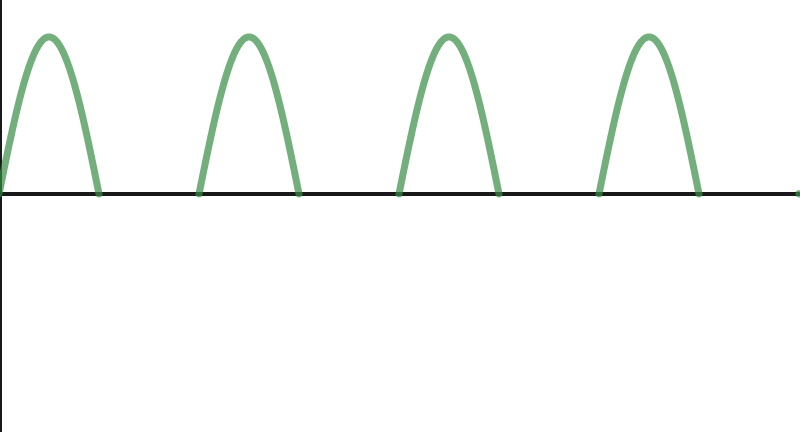
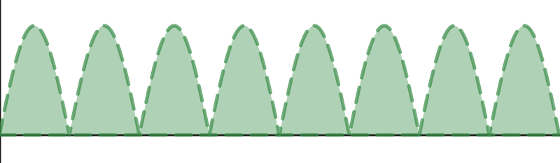
So basically, we don't give two shits about most of the qualities that make a DC supply a "good" supply. This is a lucky break because finding affordable output caps in the milliFarad range rated for 100V is next to impossible. We're just pumping juice into a huge inductor (the motor) so we get to do it dirty. So if we remove all those unnecessary features of a DC supply ... what's left? In the simplest form, you have a half-wave rectified AC signal like the one shown below with an average "DC" voltage of 54V, a rms voltage of 85V, and a ripple voltage of 170V. That's pretty darn close to the 90V output we need. Let's try it.
![]()
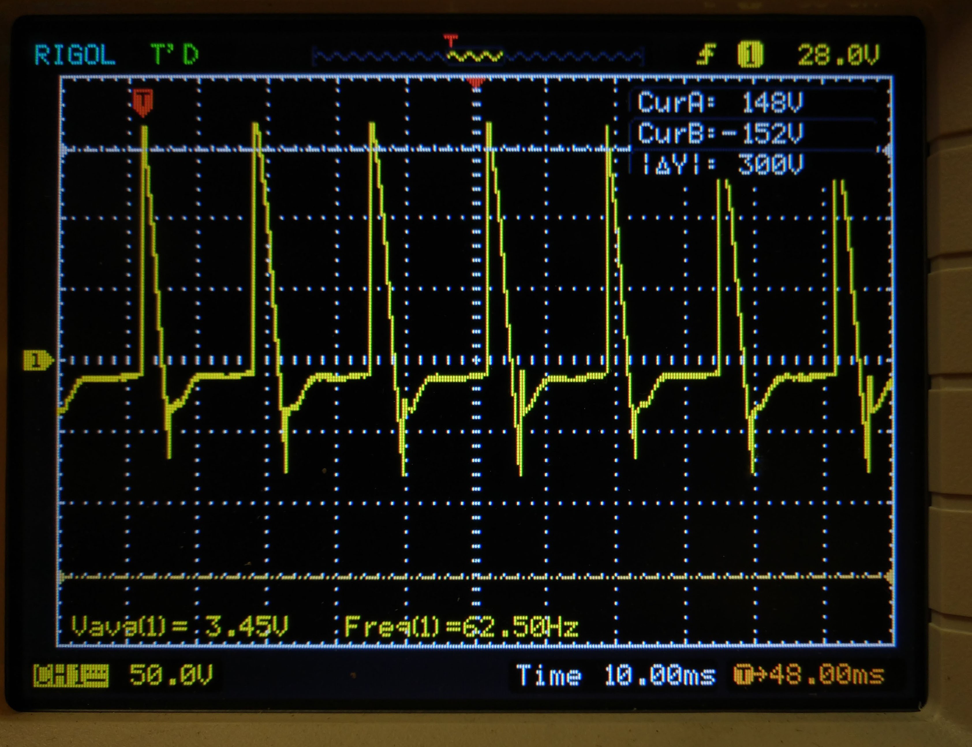
So something weird happened. I did the first test with a phase-chopped waveform to limit voltage (more later on this). Let's start with looking at the output voltage waveform of our half-wave rectifier.
![]()
![]()
The strange thing is that when the output voltage should be zero (between positive ac waveforms), it goes negative as the magicnetics of the motor feed back into the supply. While this is happening, the motor continues to run at full speed (though sounding funny). Definitely not an effective braking means, even though it is "DC". What I think is happening is that the inductance of the motor wants the current to continue (as inductors like to do) so it creates a reverse voltage (the initial spike). This initial spike then discharges over the half cycle until it gets voltage again on the subsequent half wave. Without an actively-supplied current to force that missing half-wave into positive (and thus brake the motor) - it doesn't work. Lesson learned. You might be thinking that we should just use smoothing capacitors. We did the math and simulations and the capacitance (and voltage tolerances) would be HUGE to source energy for the 8ms between half-wave pulses!
Next up is trying full wave rectification. The numbers for full-wave are a little scary, with an rms voltage of (not surprisingly) 120VDC. Added to that is the fact that when the motor sees "DC", it's overall impedance is MUCH lower and it draws much more current. We want to stop the motor slowly, not rip the shaft in half. We have some ideas to deal with this - more soon.
![]()
-
Our Subtle Ambition - Big Power, Little Footprint
05/10/2019 at 18:25 • 0 commentsWe've talked about how DC Injection will play a large role in this product but we haven't yet talked about how we'll actually make that DC. We're all used to thinking about a DC Power Supply as a trivial purchase or design, but this is something altogether different. The driving factor that makes this different is our gargantuan power requirements. We're designing our product to work with grinders motors up to 1HP so let's start by looking at the specs for a 1HP induction motor at 120V (based on NEMA MG-1):
- Full Load Current: 11 A (1.3 kW)
- Locked Rotor Current: up to 80 Amps (9.6 kW)
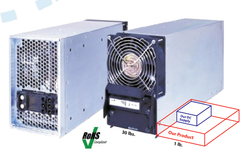
When a motor starts, the initial current hits locked-rotor-current for an instant then settles into a startup current roughly four times it's full load current. That means a 1HP grinder coming up to synchronous speed will draw 44A (5.2 kW) for a few seconds. Just as that 5.2 kW decelerated the motor from stopped to synchronous speed, we'll need roughly the same amount of power to decelerate it from synchronous speed to stopped. That's a ton of juice. For some perspective, a commercially available 5kW DC power supply costs nearly a thousand dollars and measures 17"x7"x6" and weighs over 30 lbs. Our entire product (of which DC supply is only a part) should measure less than 5"x5"x2", weight less than 1 lb, and cost less than $100.
![]()
And we haven't even begun to talk about DC output voltage. Most commercially available supplies max out around 24V but we need up to 90V DC to source enough power into the relatively high impedance windings of an induction motor. Wowzers. Now you see why this project is so ambitious. But don't worry, we have some tricks up our sleeve. More soon!
-
Ouch - Those Are My Nurtles!
04/26/2019 at 08:00 • 0 commentsAs we are getting ready to move into prototype mode, we've identified another set of requirements that we need to keep in mind as we move forward. Nationally Recognized Test Labs (NRTLs, sometimes pronounced "Nurtles") have explicit requirements for product safety and we'll need to find what category we fit in. The fact that we are an AC mains powered device makes NRTLs especially restrictive in order to limit the potential for electrocution or fire.
At first glance, it looks like we fit best under UL 508 - Motor Controllers. Unfortunately, it seems that the standard we need to meet is nearly a thousand dollars to purchase and hundreds of pages, not to mention the myriad of other standards it references. Ugh.
Excerpts I've found online list lots of conductor spacing and thermal testing requirements. We'll also want to make use of UL recognized components whenever we can. More soon!
-
Friction is so 19th Century ...
04/20/2019 at 20:45 • 0 commentsToday we want to share one of the core ideas of this project and how we believe an optimal solution would work. As we shared in our first post, the continuous spinning of a grinder after the power is turned off poses a safety problem. Fundamentally, when the power is off, the device should be safe to those around it. Our goal then, is to stop the motor quickly and safely after the power is removed.
When we searched around for how others are stopping their shop tools, we mostly came back with mechanical solutions -- some industrious souls even weld bicycle brakes to their devices. Fabricating and welding custom-made hardware to a tool isn't exactly an accessible solution for most users. Even if it was, the maintenance and impact to the surface on the machine where the brake pad comes into contact with a tool are all elements of concern. With this, we began thinking about the magnetic forces within the motor, and how we could manipulate them to get our desired result.
Before I dive into the diagrams and theory, if you’re not familiar with induction motors and how they operate, I highly recommend reading Hackaday’s article on the history of how the induction motor came to its modern incarnation and/or watching this video by Learn Engineering:
Read on below ...
---------- more ----------In this first diagram below, we show a motor with the rotor (the inside rotating part) already spinning, and the AC power supply creating an oscillating magnetic field via the stator (stationary) winding. The windings of the rotor (which connects mechanically out to the shaft) is just a few lumps or bars of dumb metal but gets current induced in it by the moving magnetic field around it. That induced current creates it's own magnetic field and the rotor spins to try to align the induced field of the rotor with the rotating field of the stator winding.
This was Tesla's innovation - the induced field ("Induction") motor. No electrical connections to the rotor (like in a brush/commutator motor) and no permanent magnets. This means less cost and less wear in industrial applications. This type of motor also boasts high starting torques and high efficiency. That's why induction motors are ubiquitous and in everything from a box fan to a power tool.
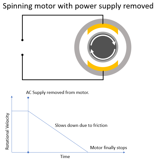
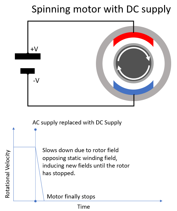
And here we show the motor immediately after the power supply has been removed. (This is a bit of a simplified model to illustrate the momentum of the grinder and the rotor, not to illustrate the effects of a collapsing magnetic field ... which we'll talk about on another post)
In the graph, we see that the motor spins down at roughly a linear rate due to the effect of friction on the rotor. Since we want to stop the rotor much more quickly, we need to add more forces which will fight the momentum of the motor! As we mentioned, others have solved this before by making the force of friction much much larger. Our approach will use the interaction of the magnetic fields instead.In this view, we show how you can introduce a new force which will fight the rotation of the rotor. By putting a DC supply across the stator winding, we’re creating a fixed magnetic field in the primary winding! Now as the induced rotor field moves with the rotor due to remaining momentum, its torque is now opposing the new static field, and the speed of the rotor will drop sharply.
So what’s the outcome of our DC driven braking? We have a new big force fighting to stop the motor, and we’re not burning through brake pads!
While using DC power to stop an induction motor isn’t exactly new technology, making the technology accessible to people using standard shop tools is. We have prototyped a few ideas, which we’ll share in an upcoming post, but we still expect quite the challenge in bringing this technology to consumers while keeping the budget consumer friendly. But hey - who doesn’t love a good challenge?
-
Pain Points & Pain Data
04/18/2019 at 07:38 • 0 commentsIn the product development and design thinking world, people often reference "pain points" when referring to a user need that is sufficiently "painful" to warrant them buying something to alleviate it. With #Grinder Minder, our investigation of pain points is a tad more nuanced. It was put best by Socrates in 381 BCE.
"In our case it all boils down to one question - how dangerous is a bench grinder and how much do people actually care?" ~Socrates, in his treatise on pre-industrial power tool safety.
Today's project log is about the first part of this timeless question - how dangerous is a bench grinder - I mean, really!? The first step in that research was learning what not do in this kind of research. For example, don't turn off image safe search when searching "bench grinder injury". Just don't. It's gross.
Based on our informal conversations with hobbyists, students, and professionals alike, people have WIDELY varying views. Some folks are scared to death of the spinning death trap that screams at them for two minutes every time they grind their tungsten for another tig weld. Others yarn on about the inherent risks of using power tools and believe that "anyone stupid enough to injure themselves on a grinder shouldn't be using one". Neither of those perspectives are particularly helpful so in advance of our more formal customer research, we spent some time looking for some data. Here are our initial findings:
- On the consumer side, the National Electronic Injury Surveillance System (NEISS) reports over 2,800 bench grinder injuries in the last five years, with over 200 being injuries to minors.
- The U.S. Bureau of Labor Statistics Injuries, Illnesses, and Fatalities (IIF) Database reports over 4,900 occupational grinder injuries and 3 deaths over the last five years.
- And both of these quantities are just reported figures and don't include the myriad of small injuries that never get reported.
Ok, now go do that image search and multiply those images times the numbers you see above. Yikes!
-
First log entry!
04/18/2019 at 07:18 • 0 commentsWe are extremely excited to start in on this competition alongside so many other talented designers/engineers/thinkers/makers. Here’s wishing everyone a fun, educational, and innovative experience!
In this log, we’re hoping to share and document our journey from identifying the pain-point to customer research to design considerations to how we’ll approach manufacturing. And to kick it all off, we thought we’d share what problem we’re trying to solve, and the kind of customer we’re designing for.
---------- more ----------Everybody loves a bench grinder -- It’s the go-to for shaving down material on a workpiece, cleaning up that weld job, prepping a surface for an adhesive, grinding ye old tungsten, and lots more. But at the end of the day, it’s still a high friction wheel with a lot of inertia and a mean top speed. Add human fingers, hands, hair, etc, and you can end up with pain, mess and sometimes serious injuries. To complicate matters, the momentum from operation doesn’t just disappear when you hit the off-switch. Any tool-titan can tell you that, like many other shop tools, the transition from high-speed-danger to safely-stopped-wheel on a grinder takes some serious time, often spinning in near silence.
With Grinder-Minder, we’re hoping to remove that danger from the equation with innovative tech and a safer-for-all approach. So who would benefit from this solution? Simply put, we would expect everyone who owns a grinder to see value in a safer work-space! We want to offer industrial solution quality at a consumer level price point.
Our next steps in our journey are to:
- begin designing the specifics of the technical solution,
- evaluate competing solutions,
- test our assumptions about our customer and their pain-point,
- and begin diving into the design requirements necessary to take this from concept to ready-to-manufacture product.
If you have some insights on what will make or “brake” (Ha! Get it?) this product, leave a comment! We’ll be extremely appreciative of any insights or feedback we can get from the community. Thanks all!
Grinder Minder
Bench Grinders are everywhere. So are fingers. May the two never meet. That's where grinder minder comes in.