Alan Green
-
Updated Planning Sheets
06/22/2019 at 04:10 • 0 comments -
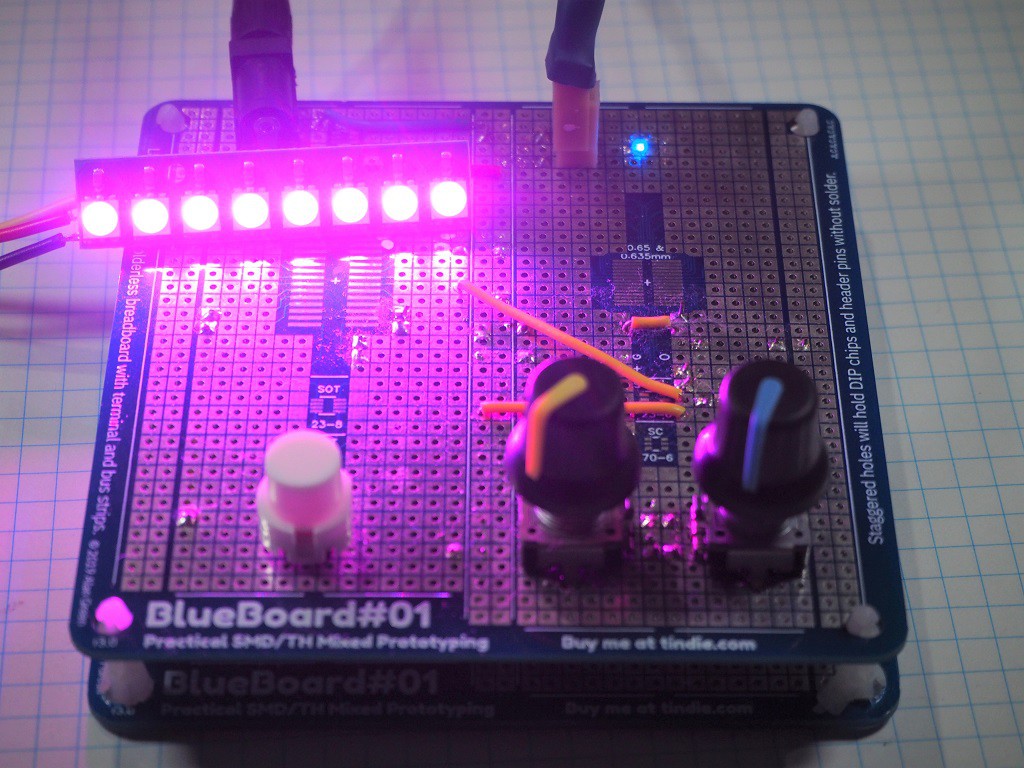
Happy Clap Switch An Example Project
06/01/2019 at 06:25 • 0 comments#Happy Clap Switch is a project that uses BlueBoard#01. It shows off a couple of construction techniques, such as drilling out holes to mount rotary encoders, and serves as a bit of a counter-example in planning - all those wires really ought to be on the underside.

-
Guide to Surface Mount Prototyping with BlueBoard #01
04/20/2019 at 03:17 • 0 comments#1 Read all the great tutorials
There are lots of great surface mount soldering tutorials around the internet. I like these ones from Sparkfun and the format makes it easy to find and refer back to. Dave Jones's videos, on his EEVblog channel, are fantastic too.
#2 Get the right Equipment
For basic surface mount soldering you will need:
- A temperature controlled soldering iron with a chisel tip 2-4mm wide. Conical tips are useful in specific situations, but they can’t push heat or drag solder as well as a chisel tip.
- 0.5mm or thinner solder wire. Thinner wire gives you more control over how much solder is applied to any point. You will want all the control you can get.
- Extra flux. Most commonly used is a flux pen, but I use Chipquick tack flux because it’s easy to apply in a controlled manner, will hold small components in place, does the job of a flux well, and cleans up nicely with IPA.
- Tweezers for holding smt components. I use a cheap pair with ceramic tips, similar to these. The ceramic tips ensure the package I am soldering stays hot and my hands stay cool.
- Magnification. A good headband visor works in most situations.
- Thin desoldering braid. You will use this regularly. The thinner the braid, the more accurate you can be mopping up excess solder.
If you’ve already been soldering through-hole components you likely have most of those things already..
Additionally, I find these items helpful:
- Isopropyl alcohol (aka IPA). Cleans flux magically. I wipe my tweezers down with it every time they get sticky from flux.
- Small paint brush for cleaning flux off boards.
- Chipquik for desoldering surface-mount components with a soldering iron. Having a little Chipquik around means that you can be braver. If you mess up, the chipquik allows you to remove a component without damage.
- A hot air rework station. Useful on its own for reseating components by reflowing solder on all their pins simultaneously.
- Solder paste if soldering with the hot air rework station. Some people prefer this when soldering a whole bunch of surface mount components at once.
- A binocular microscope. A 5-10x microscope will show lots of detail and help you more quickly learn how solder flows and the best way to apply it. It will also help you spot mistakes such as solder bridges or unsoldered pins.
#3 Solder One Pin First
Of all the advice I've received, this has been the most helpful. When hand soldering surface-mount parts, always solder a single pin first and check the alignment of the component. If you’re happy with the alignment, continue soldering the other pins. If not, heat the joint back up and move the package around.
This applies to everything from large 28 pin packages through to tiny resistors.
#4 Plan Your Circuit
Prototyping is about trying new things, but it's always best to start with a plan. Draw your schematic in your favorite schematic capture tool first.
For any circuit larger than a couple of components, it might be helpful to print these planning sheets. I draw on them in erasable pen, and there are plenty of erasures before I'm done.
#5 Be Unafraid of Making Mistakes
Making and fixing mistakes is how one learns to solder. Be patient with and forgiving of yourself. Buy cheap components in quantity and don’t worry about throwing one away.
“Experience is what you get when you didn't get what you wanted.”
-- Randy Pausch
-
A Note on the 0.65mm / 0.635mm Footprint
04/19/2019 at 23:20 • 0 commentsI've chosen to use use a single footprint for both 0.65mm and 0.635mm pitch parts.
0.65mm and 0.635mm differ by only 15 microns. That's not much.
If one were to try to mount a 28 pin 0.65mm pitch package on a 0.635mm pitch footprint or vice versa, the maximum misalignment (measured over the 7 pins from the middle of the package to the end) would be less than 100 microns - about half a leg width. Using wide pads, positioned midway between the 0.65 and 0.635mm pitch (0.6425mm) we can accommodate a part in either package.
-
A Note on Exposed Pads
04/19/2019 at 23:16 • 0 commentsSome dual inline package parts have an exposed pad, which is used as a heatsink for the part. This is particularly common for parts that drive large currents (example). However, because of the variety of widths parts come in, and how that means the pads have to be arranged, I’ve chosen not to add an exposed pad to the footprints on BlueBoard#01.
There are several alternatives:
- Cover the exposed pad with kapton tape and solder it anyway. You won't get the same thermal performance, but it might be enough for your prototype.
- See if you can find an alternative footprint for the part that doesn't use and exposed pad. The LM25085, for example comes in several packages, one of which doesn't use an exposed pad.
Please let me know if you were unable to use BlueBoard#01 for your project because you needed to use a particular part with an exposed pad, but were unable to.
-
Why Does The World Need BlueBoard #01?
04/19/2019 at 22:58 • 0 commentsUsing BlueBoard#01 to prototype with surface mount components is often faster than the the two main alternatives.
Alternative 1: Custom PCBs
Getting started a BlueBoard#01 that you happen to have hand is certainly faster than having a prototype PCB manufactured. This is why we sell them in stacks.
BlueBoard #01 then makes it simple to remove, replace and experiment with components and circuits. Iteration is fast.
Fixing mistakes is much simpler than with a custom PCB: no need to scrape back soldermask from a track, or try to wire to the middle pin of a 0.5mm pitch 10-MSOP.
Alternative 2: Solderless Breadboards
If you have more than a couple of SMT components, solderless breadboards can be difficult to work with.
Noise and inductance can be particular problems around analog devices, oscillators and switch mode power supplies. All of these types of circuits go better when the components are securely connected with as short a path as possible between points. Having connections you can trust makes everything go faster because there's less debugging of unimportant problems.
I also find that dealing with more than a few breakout boards is annoying. Mounting components to a breakout board is more difficult than mounting to a larger PCB.
In summary
BlueBoard #01 brings some of the features of solderless breadboard to surface-mount prototyping in an environment that is faster to get going with than and electrically similar to a finished PCB.