Jana Marie
-
Feature list for V2
05/08/2019 at 17:35 • 0 commentsVersion V1.1 is now finished, but I am not happy yet. Since I want to change a few things to have Enlightened Otter as a finished, robust "product", I want to build a second version. :)
The following features should be added/changed:
- Move all parts to the bottom side of the PCB
- Change battery clips from THT to SMD
- Add fuses
- Remove ground-plane around the touch-pads
- Better power plane splitting
- Change ESP footprint to a smaller one
- Add moodlight leds
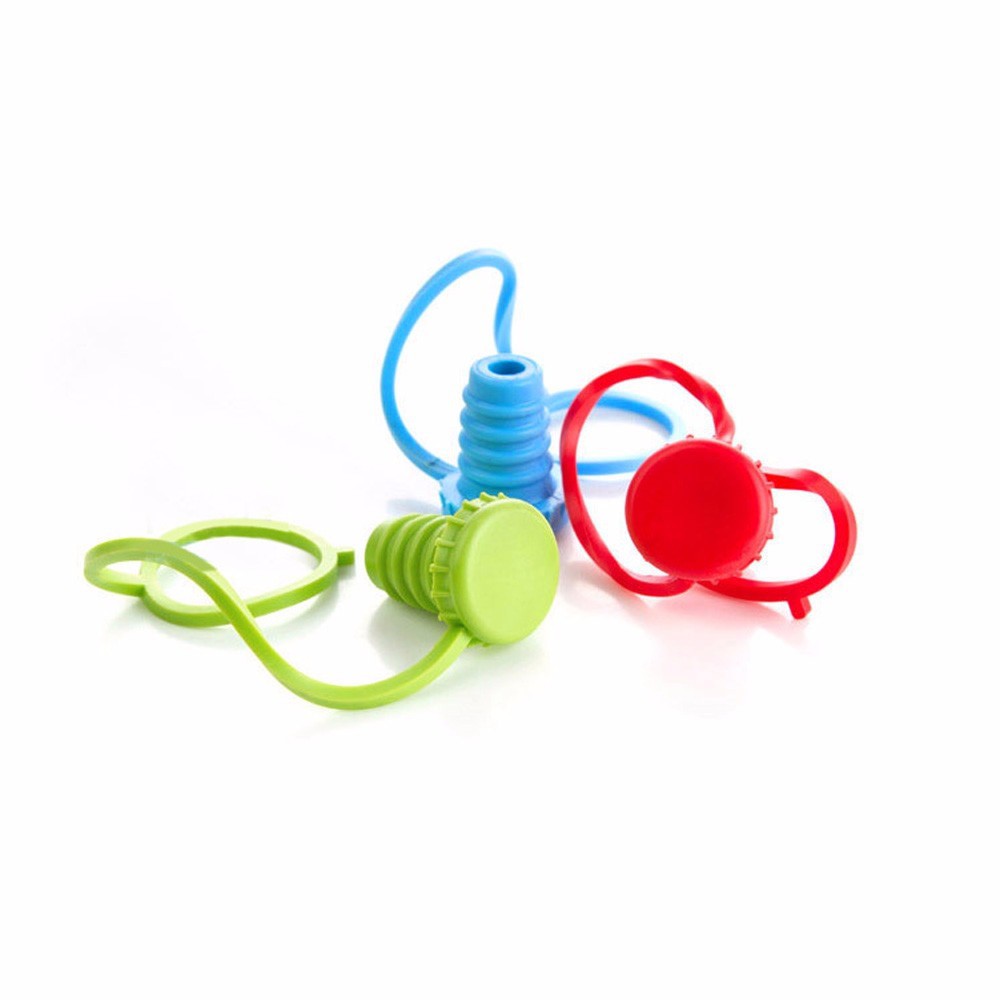
@Jan pointed out, that I could use silicone bottle caps instead of a 3D printed thread. I really like that idea so I ordered different models from aliexpress. Most promising cap/plug is the following one:
![]()
-
Measurement of light output
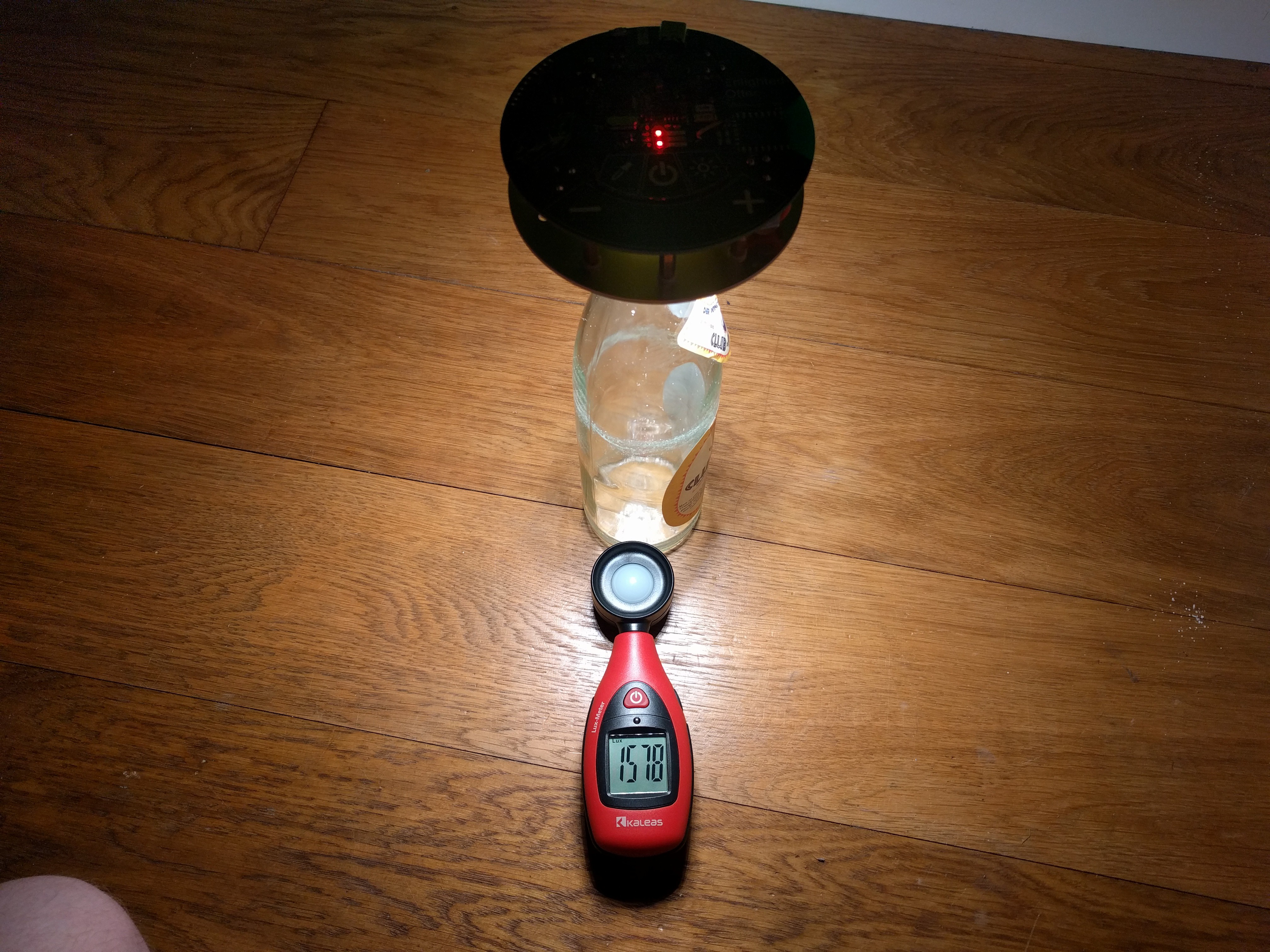
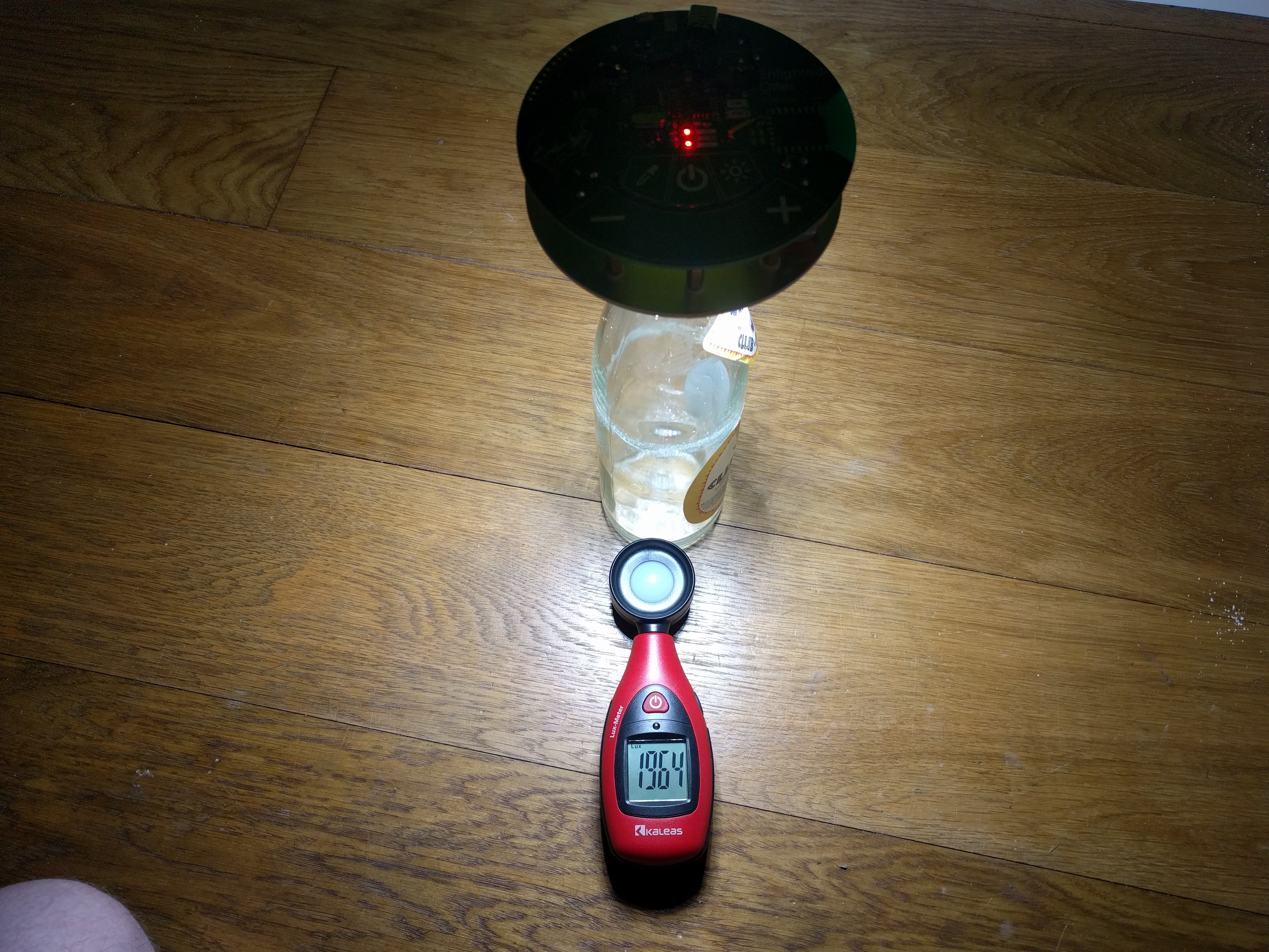
04/24/2019 at 11:01 • 0 commentsWith a luxmeter I measured the light output of Enlightened Otter at a color temperature 3500 K and 6500 K, the resulting brightnesses are 1600 lx and 2000 lx. I'm quite happy with that, for comparison, recommended minimum brightness desk lighting is 800 lx.
![]()
![]()
I used the values to create the following specification table:
Iout (per channel) 0-500mA Vout (per channel) 0-18.5V Pout (per channel) 0-7.5W Illuminance (3500k @400mA) 1600lx Illuminance (6500k @400mA) 2000lx Vin (USB) 4.8-14V Iin (USB) 3A (max) Vbat 3.8V Ibat (max) 5A Boost frequency 500kHz Iripple (@2.5kHz) <0.5mA -
Enlightened Otter V1.0/V1.1
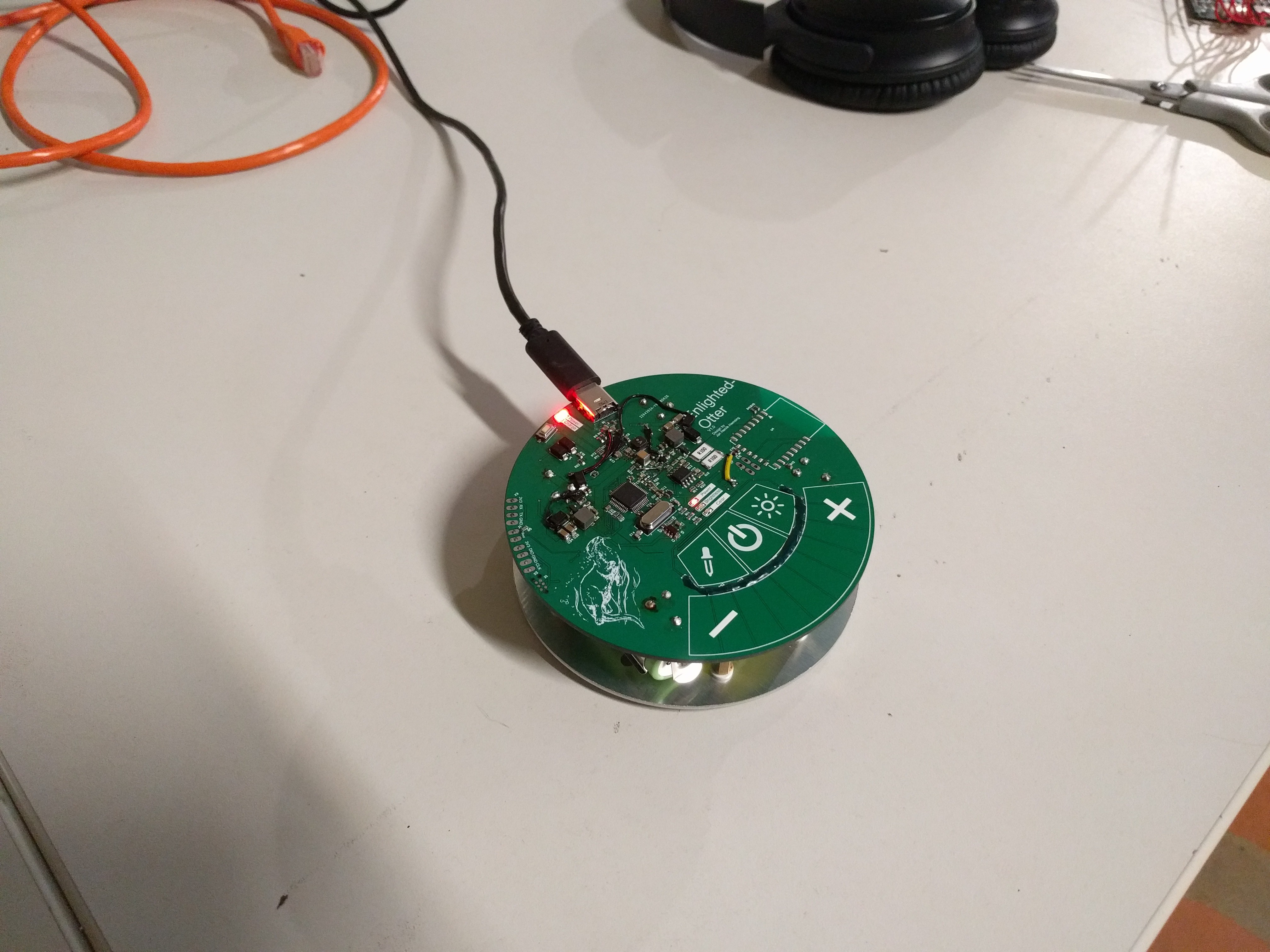
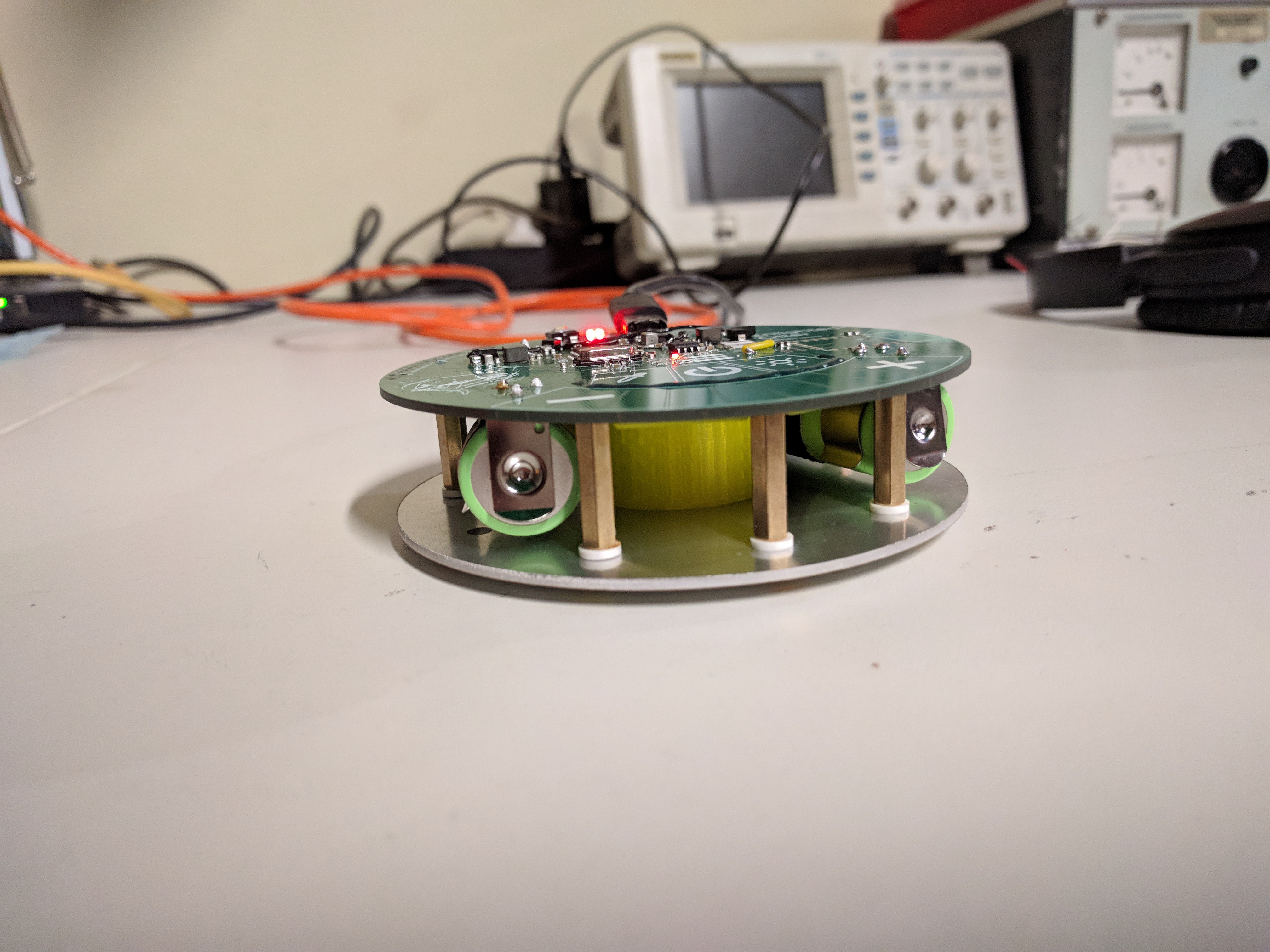
04/24/2019 at 10:36 • 0 commentsWith the boards from the previous two Logs we can already assemble an Enlightened Otter. There is not much to that: Snap in two batteries, add the 3D printed part, add insulators, add nuts and you're done.
![]()
![]()
The software is written in C with the STM32 HAL Lib and Makefiles. The difficult part here is the hardware initialization, since most of it runs offloaded from the CPU using HRTIM triggered ADC.
All the bodges of V1.0 where removed in V1.1. A major problem both versions have, is ghost touch input from boost converter noise. This can be solved by lowering the sensitivity, but then the input is no longer so responsive.
The charging of the batteries and the battery operation function perfectly. Also the Boost converter works very well, but the Mosfets get very warm, in version 2.0 a new package has to be chosen. The current measurement and the controller have no problems, a current control with a current ripple of < 0.5mA is possible.
The protective devices trip in the event of a fault.On the board I have provided a footprint for an ESP, but I haven't equipped and tested it yet
-
Main PCB V1.0/V1.1
04/24/2019 at 09:31 • 0 commentsTo drive the LEDs, we need two boost converters from VBAT (3.2V-4.2V) to VLED (~10V-16V). Since I want to keep the costs as well as the number of components low, I decided for a processor, which can implement the Boost converter in software.
The STM32F334 has a timer with a clock frequency of 4.6Ghz*, comparator inputs, reasonable ADCs and a touch controller. So I get PWM at 500kHz with a resolution of >13 bit. The ADCs are needed to regulate the LED current via the boost, the comparators are used to stop the boost in a fault condition in shortest time without software interaction.
A schematic can be found here.
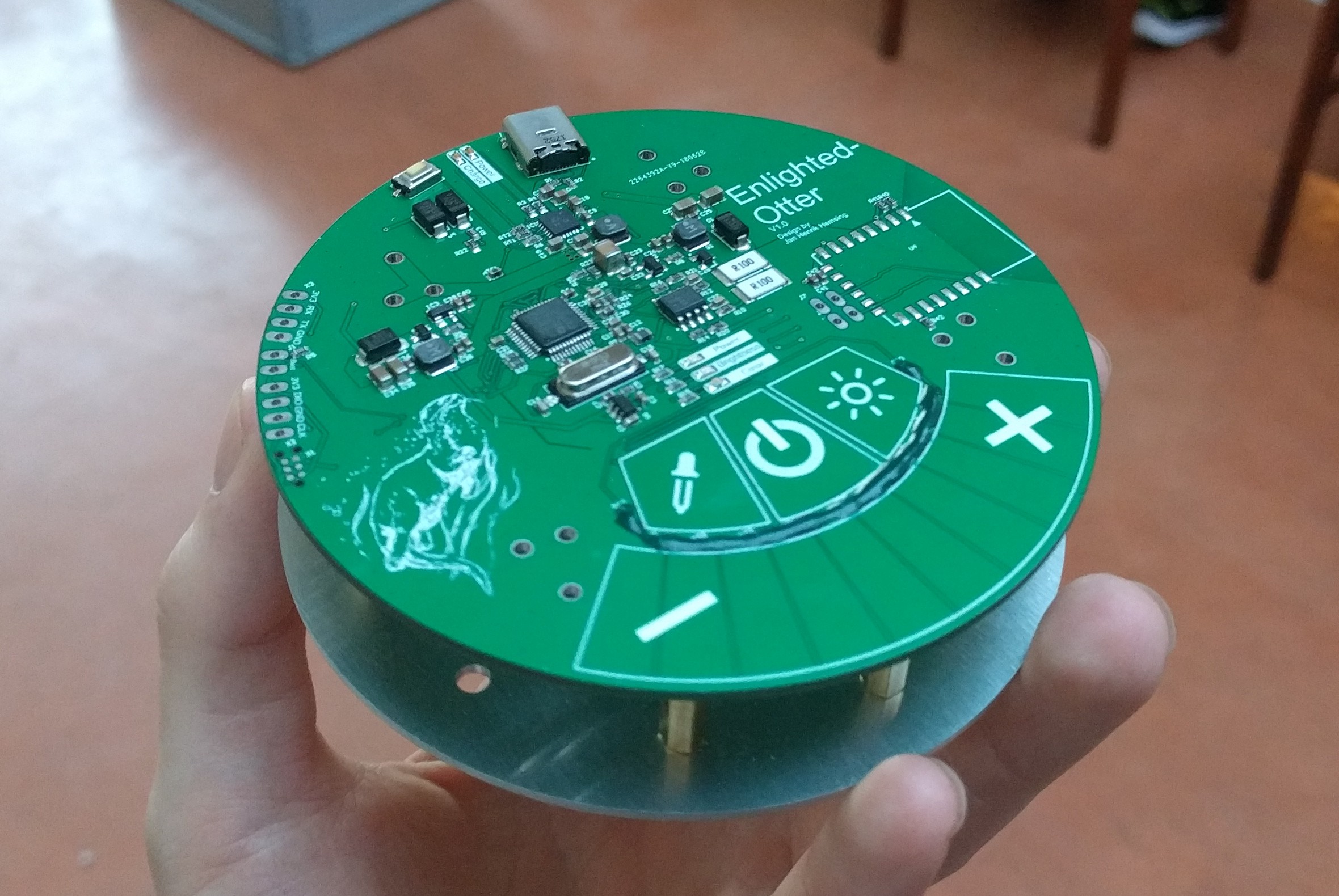
I want to use the Touch controller (TSC) for the input of Enlightened Otter. Beside a slider I need three buttons (on/off, brightness, color temperature). This allows you to distinguish between brightness and color temperature and adjust them with the slider. To save pins I implemented a resisitive interpolation of the touch slider. Thus three pins result in a slider with a resolution of > 300 points (measured). Atmel has a good application note on this topic. Unfortunately the interpolation resistors are a source of error if you touch them, so I put a solder resist mask as insulation/protective lacquer on them.
![]()
PCB-Touch is a quite neat input method, cheap and easy * Of course the STM doesn't have a 4.6Ghz clock, but 32 144Mhz clocks with phase-shifted timers.
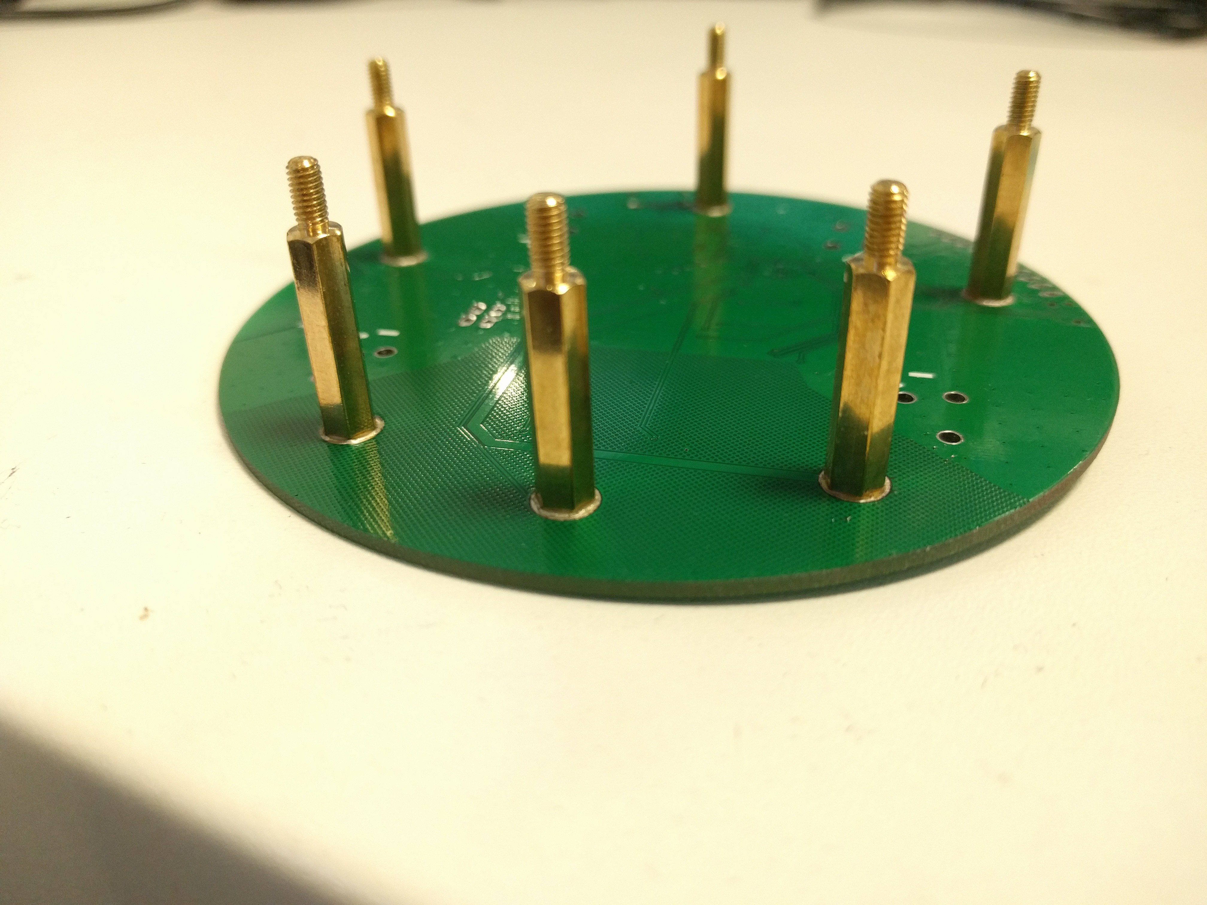
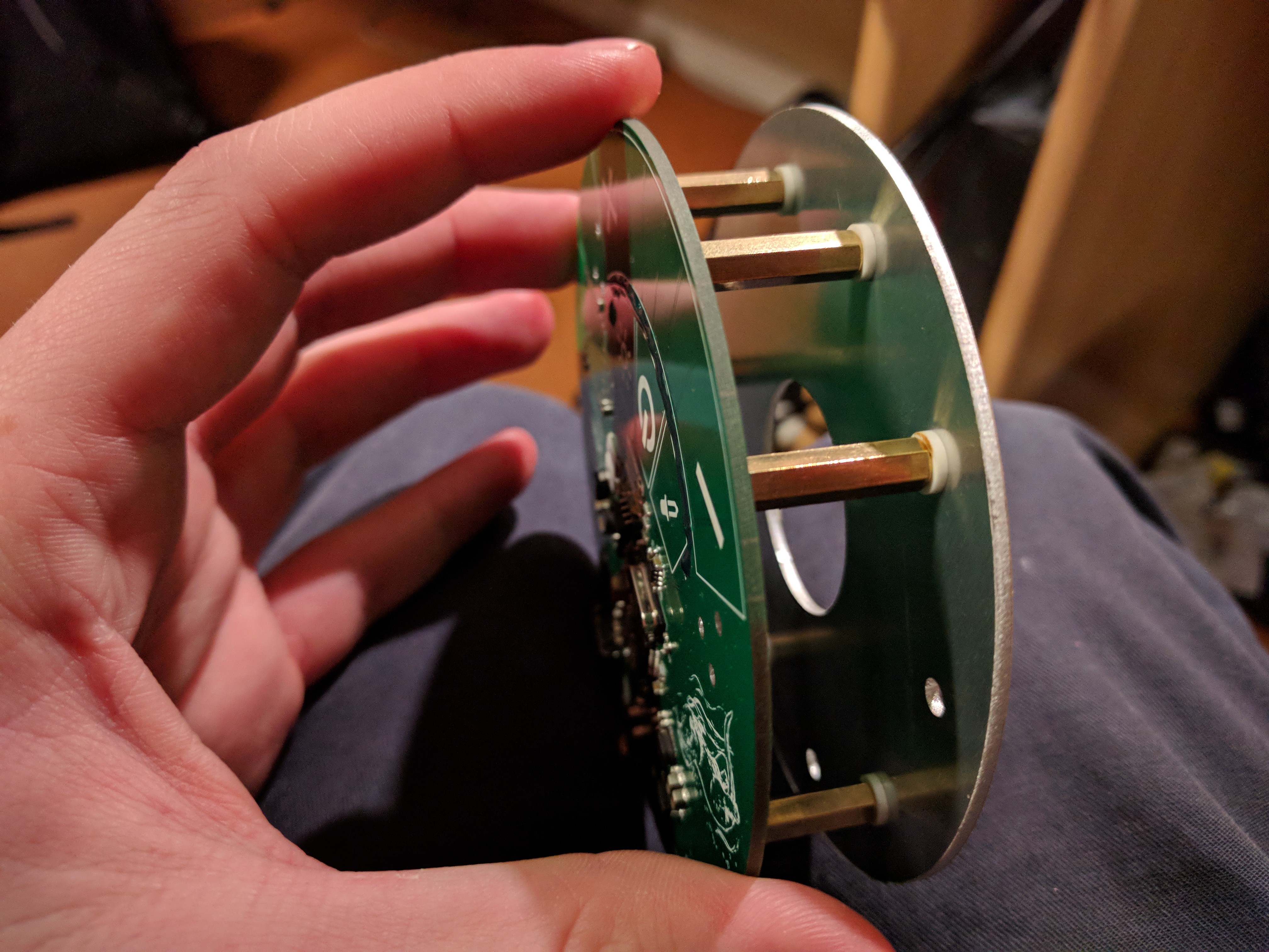
On the backside of the PCB spacers are soldered as SMD to connect both PCBs, so I don't have screw holes on the topside. Unfortunately this is also rather fiddly, spacers tend to fall over when soldering.
![]()
As battery connector I used "Keystone 54", they have the smallest footprint available for 18650 type cells.
-
LED PCB
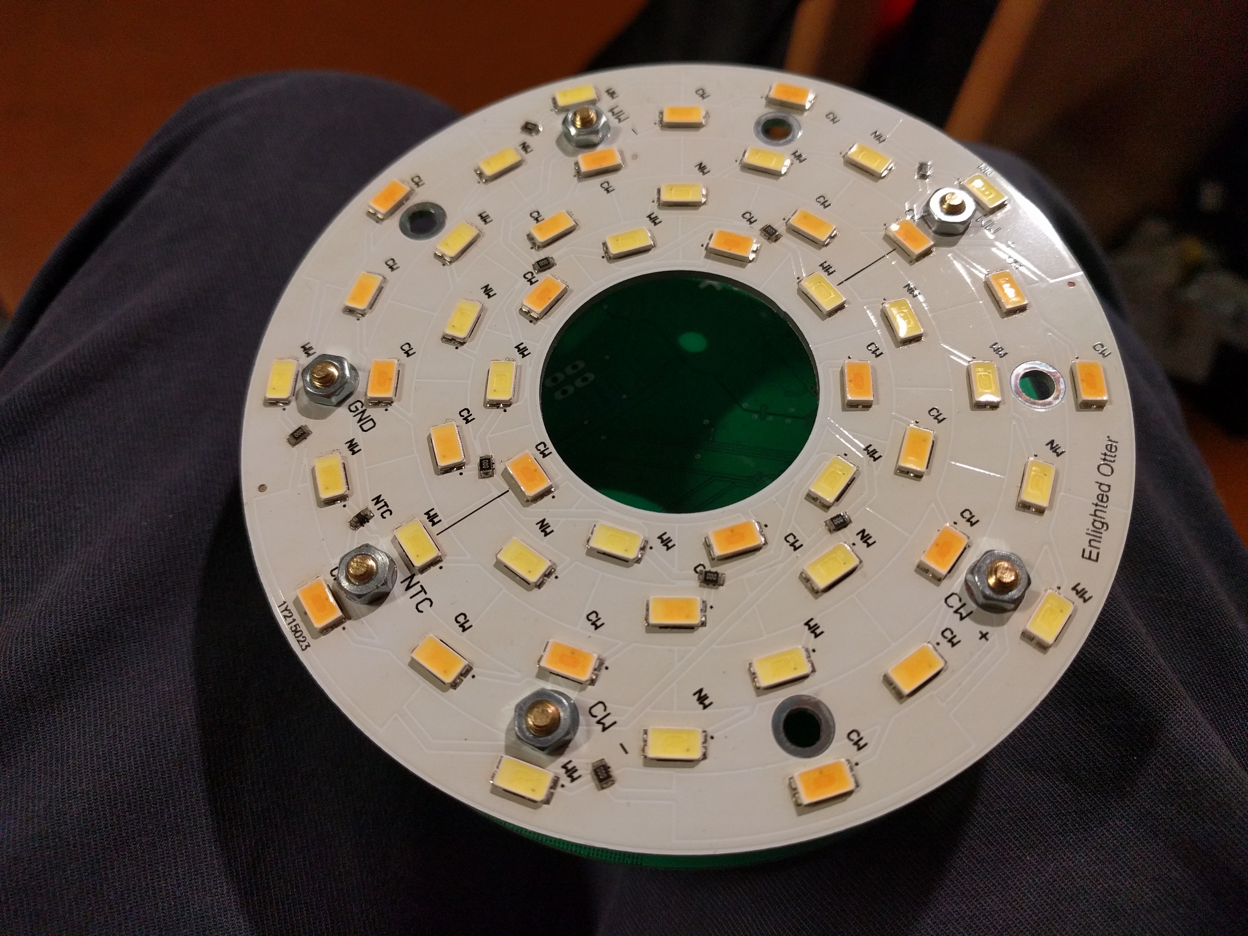
04/23/2019 at 19:59 • 0 commentsAn approximate estimation showed that with about 25 LEDs I could achieve an adequate brightness for working. So 50 LEDs have to be on one PCB, 25 of each colour. An arrangement of 5*5 LEDs (5 in series, 5 rows in parallel each) is recommended, so we get a voltage of ~16V at a current of ~500mA per color.To dissipate the waste heat from the LEDs we need an aluminium core board.
The creation of the layout is a little fiddly, because with an aluminum core PCB a second layer is very expensive. Single layer aluminium core boards cost only about 1.5€ per 100*100mm per piece at 15 pcs. To cross tracks you have to use zero ohm resistors. However, since we only need a few components in a simple sample, this should not be a problem. In addition to the LEDs an NTC is used to measure the board temperature.
![]()
LED-PCB + Spacer Since we want to make the connection between the boards with spacers and an aluminium PCB is made of aluminium from behind, we have to insert an insulation here. Fortunately, spacers and FET-screw-insulators have the same diameter.
![]()
-
Basic Design
04/22/2019 at 16:41 • 0 commentsThe idea for the mechanical design was already born at the GPN. Since lamp holders and feet are unnecessary balast during transport, I first looked for a replacement for them. A Resurce that is available on every event are empty bottles, especially Club Mate bottles. So I want to use an empty mate bottle as a base.
Another advantage that came up later, is that a mate bottle with a lamp on top is always below eye level and therefore does not dazzle.
With a bottle as the base, a round "UFO"-like design with batteries between the LEDs and the main board is obvious. Since the LEDs have to dissipate some energy/heat, I will have to use an aluminiumcore pcb for the LED board. Another thing to keep in mind is, that a thread for the bottle is needed, it will be 3D-printed and needs a matching hole. Such a circuit board is not available at AliExpress, so I have to design it myself.
All other components will find their place on the main pcb. This includes a STM32f334 as processor and a RT9466. I chose the STM32f334 because it has a 4.6Ghz timer which can be used for PWM. Also the processor has hardware comparators which can stop the timer in case of emergency (e.g. short circuit, overvoltage) and a touch controller. I want to use a PCB touch slider as well as touch buttons for control of Enlightened Otter.
The RT9466 is a highly integrated battery management IC often used in smartphones. I want to use it because of the power path and the shipping mode feature. Especially the shipping mode feature allows me to store Enlightened Otter when not in use for long time.
As I want to store two 18650 type Batteries in between the two PCBs, I have to find a way to connect both boards while having enough space. I am thinking about soldering pcb-spacer screws to the main board.
With all that settled I can start with prototyping. -
Inspiration
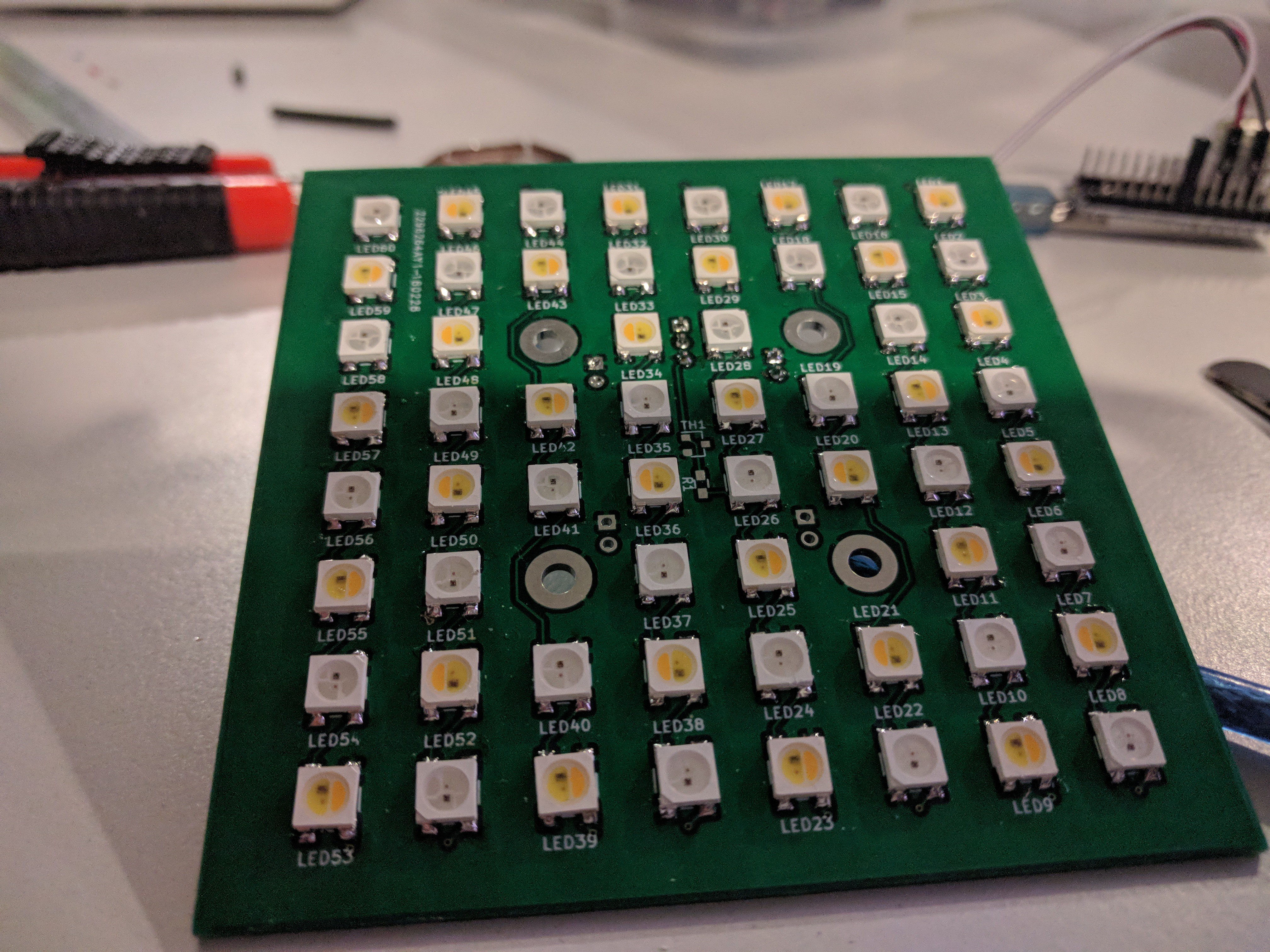
04/22/2019 at 16:25 • 0 commentsI was inspired to do this project by Thunfisch at the GPN18. He brought a 10*10 px LED matrix to the event, which was used instead of RGB LEDs with WW,CW and Amber leds.
![]()
Of course, I have not only equipped my matrix with white LEDs ;) I thought the idea of my own little working light was pretty cool, so I collected what features I need. The summary is:
- Small footprint, lightweight
- High CRI
- Flicker-free
- Battery operation
- Easy to operate
- Colour temperature adjustable
That was the point where I started Enlightened Otter.