Xabi Z
-
Making it ring
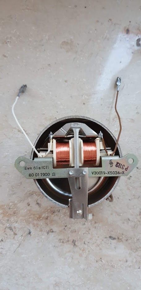
04/26/2019 at 11:48 • 0 commentsThe second most significant feature of these vintage phones, after the rotary-dial, is the characteristic ringing bell. Here the thing gets a little more complicated: Old phones have a electromagnet driven bell inside which sounds wonderfully well, but also requires very specific signals to be driven.
![]()
In order to drive the bell we will require an at least 30V AC signal with 20-25 Hz frequency, which of course needs to be turned on and off appropriately (1 second ringing, 4 seconds pause, and repeating). In really old telephone exchanges this signal was produced by a electric little motor switching on and off contacts at the specified rate. These are the steps to obtain such a signal:
- A DC voltage of 30V needs to be obtained: This can be done either boosting up the 5V provided by our Raspberry Pi or down-converting and rectifying a higher voltage (such as the one from the AC sockets for instance).
- Once this is achieved the signal needs to be switched with a frequency of 20-25 Hz and the polarity needs to be inverted so that the electromagnet ringing the bell functions properly. This can be achieved by a PWM switched DC converter and an H-Bridge
On the other hand they are also commercially available ringing signal generators, which is the out of the shelf solution.
![]()
I choose to buy the Ringer module described above from E-Bay. Apparently they are used to generate ringing signals for backwards compatibility of older line-phones. It cost $25 and was shipped from Israel.
The module has 5 wires:
- V+ (12V)
- V- (GND)
- RNG1 and RNG2 : The bell is connected between these two
- INHIBIT
Unfortunately, the signal generator is continously active until the INHIBIT signal is pulled high, 12V in theory. Somehow I managed to make it work with the 5V digital output from the Raspberry Pi.
I also used a step-up 5V to 12V converter to feed the newly acquired ringer module.
The whole setup needed some high valued capacitors in order to account for power demand peaks.
-
Making everything work together
04/26/2019 at 09:41 • 0 commentsCurrently we have a functioning Bluetooth set but we can only place calls, and interact with it through the cold touchscreen of our smartphone.
It is time to use the peripherals of the rotary phone to answer calls, dial-numbers, and end-calls.
Ofono exposes the most important methods to the D-Bus. D-Bus is an inter-application messaging system for Linux. D-Bus can be easily accessed and controlled using the Python module 'dbus'. The following snipped shows how to place a call:
import sys
import dbus

number = 123456789

bus = dbus.SystemBus()

manager = dbus.Interface(bus.get_object('org.ofono', '/'), 'org.ofono.Manager')

modems = manager.GetModems()

# Take the first modem (there should be actually only one in our case)
modem = modems[0][0]

hide_id = "default"

print("Using modem %s" % modem)

voice_call_manager = dbus.Interface(bus.get_object('org.ofono', modem), 'org.ofono.VoiceCallManager')

voice_call_manager.Dial(number, hide_id)
More information about the complete Ofono API can be found on its GitHub repository documentation. Specifically the most interesting part is the VoiceCallManager API.
Our phone should be able to place calls, answer them, and hang them up. On top of that, it would be nice if it could replicate all bells and whistles (pun intended) of the rotary-phone. The plain old telephone system (POTS) produces a 440 Hz tone when the receiver is lifted in order to signal that the line is available for use.
Moreover, we want to also exploit additional functionalities thanks to the internet connection of our new phone. We could, for example, use the numbers dialed when the receiver is hooked to trigger features such as spoken weather forecast, spoken mail reading, shutting down the system, or fast dialing; while the numbers dialed when the receiver is lifted will work as they were intended to: by dialing that number on our smartphone and starting the call.
The telephone.py script contained on this project implements the most important of these described functionalities. We will copy this file on our /home/pi/ directory.
Once our script is finished, we can add it as a service that runs on boot for headless operation. We will create the file /etc/systemd/system/telephone.service and copy the following text in it:
[Unit]
Description=Bluetooth Telephone interface
After=ofono.service
Requires=sound.target

[Service]
Type=simple
ExecStart=/usr/bin/python3 /home/pi/telephone.py

[Install]
WantedBy=multi-user.target
This will force to run our system as soon only if our soundcard has been loaded properly and after ofono service is initiated. Afterwards the service needs to be enabled with:
systemctl enable telephone.serviceOur telephone interface script will be now loaded on each reboot.
-
Setting up the Bluetooth
04/25/2019 at 21:09 • 7 commentsBluetooth allows to communicate between different types of devices and with different purposes. Therefore, several profiles exist for each communication type. The classical and best known ones are:
- A2DP (Advanced Audio Distribution Profile): It is mostly used on unidirectional Bluetooth audio system such as wireless Bluetooth speakers or multi-room audio streaming.
- HIP (Human Interface Profile): As the name suggests used for all Bluetooth mice, keyboards, and other input devices.
- FTP (File Transfer Protocol): User for file transfer as the name shows. Good old way file exchange between not-so-smartphones when the cloud was still just a mass of condensed water.
- HSP (Headset Profile) and HFP (Handsfree Profile): Used for communication between a Bluetooth enabled device and a headset.
HSP fits perfectly our needs. It allows us to handle the signaling (dialing, call start/end) between the smartphone and the telephone as well as the audio stream exchange. On top of that, one must make the distinction between the HSP "Server" and the HSP "Client". In our case the Pi will function as client while our smartphone will be the server.
Unfortunately for us, the A2DP profile is the only straightforward out-of-the box implemented profile for the Raspberry Pi so enabling our Pi Zero to work as a HSP will not be such a trivial task.
Three applications take part on the whole Bluetooth routing:
- The BluEz Bluetooth agent: It is in charge of managing the pairing, trusting, and connection with any device.
- Ofono: Originally developed by Intel and Nokia for their phones, this software package will allow us to handle all telephony related signaling.
- Pulseaudio: While Ofono handles the signaling, once a call is established it is necessary to route all incoming and outgoing audio traffic from our old phones receiver all the way to the smartphone through our Bluetooth connection. Pulseaudio's capabilities to handle HSP Bluetooth profile are relatively newly added and we can say that they are still in continuous improvement. The current stable version of Pulseaudio is version 12, however only version 10 is included on the default Raspbian Stretch repository. Some other tweaks need to be performed to make the latest Pulseaudio compatible with our little Raspberry.
The first two packages can be installed from the standard Raspbian Stretch repository with the following command:
sudo apt-get install pi-bluetooth ofonoA small change needs to be made to the dbus policy of ofono in order to be able to open the audio link properly and communicate with other processes. The file /etc/dbus-1/system.d/ofono.conf needs to be modifies so that the line reading
  <policy context="default">
    <deny send_destination="org.ofono"/>
  </policy>
reads
  <policy context="default">
    <allow send_destination="org.ofono"/>
  </policy>
Compiling Pulseaudio
On the other hand, the Pulseaudio source requires a small modification and needs to be manually built. It can be fetched from the project's GitHub repository:
git clone git://anongit.freedesktop.org/pulseaudio/pulseaudioThe problem here lies on how Pulseaudio implements the HSP Audio routing. When two Bluetooth enabled devices establish a HSP Audio link, the data is exchanged by means of Synchronous Connection Oriented (SCO) packages. This is a real-time narrow-band protocol without package retransmission suitable for Bluetooth voice exchange. The synchronization between the transmitting and receiving parts is made by sending one SCO package per received SCO package.
This all works perfectly if both packages have same or very similar size, however Pulseaudio hard codes the SCO package size to 48 bytes, while the controller from the Raspberry Pi negotiates a package size of 60 bytes. This behavior was observed by using the btmon debug tool:
[btmon extract]
Therefore, the packages sent by the Android phone comply with the negotiated length of 60 bytes but the packages sent from the Raspberry Pi have a length of 48 bytes. This causes terrible audio desynchronization once the link is established which ultimately leads to severe underruns and latency issues that can be both heard and seen on the Pulseaudio log.
For this purpose, the Pulseaudio source needs to be changed to account for the negotiated package size of 60 bytes.
The changes need to be made on the files
src/modules/bluetooth/backend-native.c
and
src/modules/bluetooth/backend-ofono.c
from the Pulseaudio source. The line that reads
*imtu = 48;
has to be changed to
*imtu = 60;
Once this is done the Pulseaudio module can be compiled by calling
sudo apt-get build-dep pulseaudio
./bootstrap.sh
make
sudo make install
sudo ldconfig
The process of building is not complex but quite time consuming on our slow little Pi, so be sure to grab a coffee and have enough spare time before starting it. The first command automatically installs all build dependencies for Pulseaudio. Be sure to enable the developer sources in the /etc/apt/sources.list file by commenting out the line starting with deb-src.
Although not compulsory we can make one change more to the Pulseaudio configuration to limit the Bluetooth profiles to HSP only. By default, Pulseaudio should automatically switch from the A2DP profile HSP on demand. However, this switching can be a source to many problems and anyway we don't intent to use our old phone as a Bluetooth speaker for listening music.
The changes take place in the file /etc/pulse/default.pa
.ifexists module-bluetooth-discover.so
load-module module-bluetooth-discover headset=ofono
.endif
By forcing the 'headset' to 'ofono' we will guarantee that Pulseaudio will only serve the HSP profile. Now Pulseaudio is installed and ready to work.
Connecting the smartphone
We will use the Bluetooth controller to pair, trust, and connect to our device. The Raspberry Pi Zero W already includes a built in Bluetooth so there is no need for any external adapter, anyway it only has a single USB port already occupied by the USB sound-card.
We will turn on the Bluetooth from our smartphone and make it discoverable. We will use 'bluetoothctl' from the Pi to perform the whole process:
bluetoothctl
power on
scan on
With this we will find the MAC address of our device in the format of XX:XX:XX:XX:XX:XX
We will use this address to identify our device. Next, the pairing, trusting, and connecting process can be performed using
pair XX:XX:XX:XX:XX:XX
trust XX:XX:XX:XX:XX:XX
connect XX:XX:XX:XX:XX:XX
If everything worked properly, our smartphone should be connected to the Pi with a HSP profile, ofono should be able to place and handle calls, and Pulseaudio should handle properly all audio exchange between the devices. We can already test the Bluetooth capabilities of our new device by placing a call using our smartphone.
-
Programming the interface
04/25/2019 at 20:46 • 1 commentThe software tasks can be divided into the following parts:
- Setting up the audio: The USB Card needs to be set as the main card
- Reading the dialed numbers: The rotary-dial needs to be read and its pulses translated to the dialed number
- Reading if the hook is lifted: It was necessary to lift up the hook to start dialing a call. We want to replicate this behaviour. We also want to use the action of hooking down the receiver to end a call.
- Setting up a Bluetooth link to our smartphone: Ideally the tabletop-telephone needs to be detected as a Bluetooth hands-free set and the appropriate signals (start call, hang call, audio-link) have to be exchanged between the smartphone and the "dumb-phone".
Setting up the audio
The Raspberry Pi Zero with the latest Raspbian operating system should already automatically detect most of the USB sound-cards. To avoid any sort of confusion between devices we will disable the builtin audio by commenting the following line out from the /boot/config.txt file.
dtparam=audio=on
Afterwards we can already test the speaker by typing the following command:
speaker-test --test=wav -w /usr/share/sounds/alsa/Front_Center.wavWe should be able to hear "Front Center" repeatedly spoken from our receiver's speaker.
We will come back to the audio setup when configuring the Bluetooth. The services we are willing to use for the Bluetooth hands-free profile require Pulseaudio to be modified, compiled, and installed from source.
Detection of signals
The dialing pulses and the hook can be read using the RPi.GPIO Python module. The following class snippet can be used to place the decoded number into a queue and be accessed from other threads (more about multi-threading and queuing can be read here).
class RotaryDial(Thread):
    def __init__(self, ns_pin, number_queue):
        Thread.__init__(self)
        self.pin = ns_pin
        self.number_q = number_queue
        GPIO.setup(self.pin, GPIO.IN, pull_up_down=GPIO.PUD_UP)
        self.value = 0
        self.pulse_threshold = 0.2
        self.finish = False
        GPIO.add_event_detect(ns_pin, GPIO.FALLING, callback=self.__increment, bouncetime=90)

    def __increment(self, pin_num):
        self.value += 1

    def run(self):
        while not self.finish:
            last_value = self.value
            time.sleep(self.pulse_threshold)
            if last_value != self.value:
                pass
            elif self.value != 0:
                if self.value == 10:
                    self.number_q.put(0)
                else:
                    self.number_q.put(self.value)
                self.value = 0
Similarly we can detect if the receiver is hooked or lifted:
# Receiver relevant functions
GPIO.setup(self.receiver_pin, GPIO.IN, pull_up_down=GPIO.PUD_UP)
    if GPIO.input(self.receiver_pin) is GPIO.HIGH:
        self.receiver_down = True
    else:
        self.receiver_down = False
GPIO.add_event_detect(self.receiver_pin, GPIO.BOTH, callback=self.receiver_changed, bouncetime=90)

def receiver_changed(self, pin_num):
    if self.receiver_down:
        self.receiver_down = False
    else:
        self.receiver_down = True
Notice that in my case because of wiring optimization I chose to join both switches to active low value (meaning they will be grounded when closed). Therefore the pull-up settings have to be set accordingly.
![]()
-
Wiring everything up
04/25/2019 at 19:06 • 0 commentsWe want to replace the ancient simplicity of the Siemens manufactured board by the modern complexity of the Raspberry Pi Zero W. The project, however, also aims to keep the component count low and avoid using unnecessary components if they are not compulsory: The phone already has its own speaker and microphone? So why replace them with their modern counterparts? Yes, I know an old carbon microphone may not sound precisely crystal clear, but it will add another bit of vintage touch to our project (and a 1980 flavored frustration to the one talking to us on the other side of the line); our smartphone already has all required communication functionalities and chatting applications? So why re-implement them on the Pi? Let's just figure out how to connect our new old rotary-phone to our old new smartphone. The solution will be squeezing the Bluetooth capabilities of the Raspberry Pi Zero to the maximum.
Wiring the rotary dial
Another important point to preserve the touch of this old phone is conserving and using the rotary dial as it was intended to. Old rotary dials require the finger to be inserted in the hole corresponding to the number to be dialed and turning the wheel clockwise until the stop. When the wheel is released, a spring rewinds it back to its original position. On its way back the dial opens and closes a contact several times producing a train of equally spaced pulses. The amount of times this contact is closed and opened corresponds to the dialed number. The diagram below shows such a pulse train:
![]()
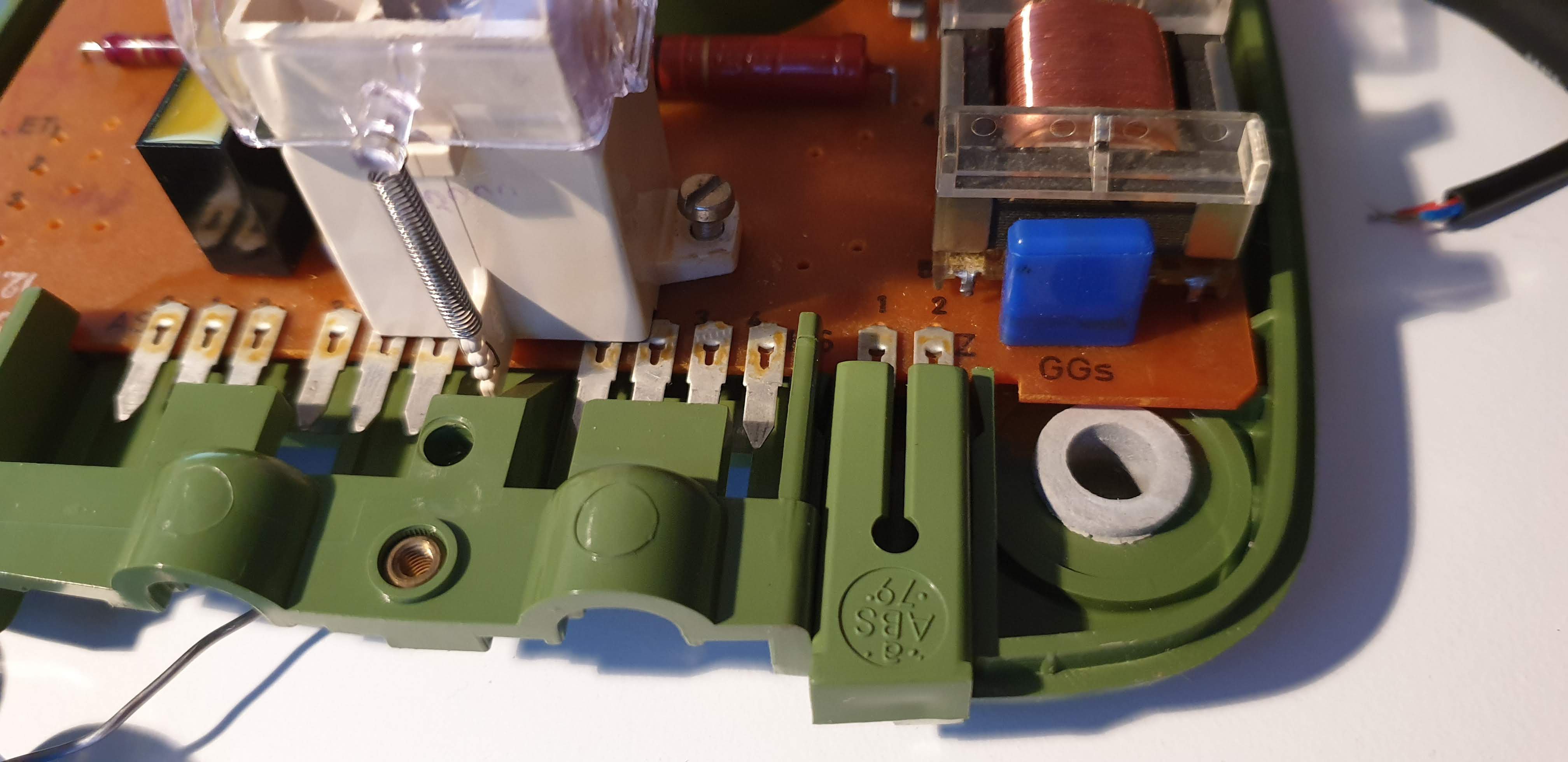
A four pin socket named NS (Nummerschalter) links the circuit board to the rotary dial part.
![]()
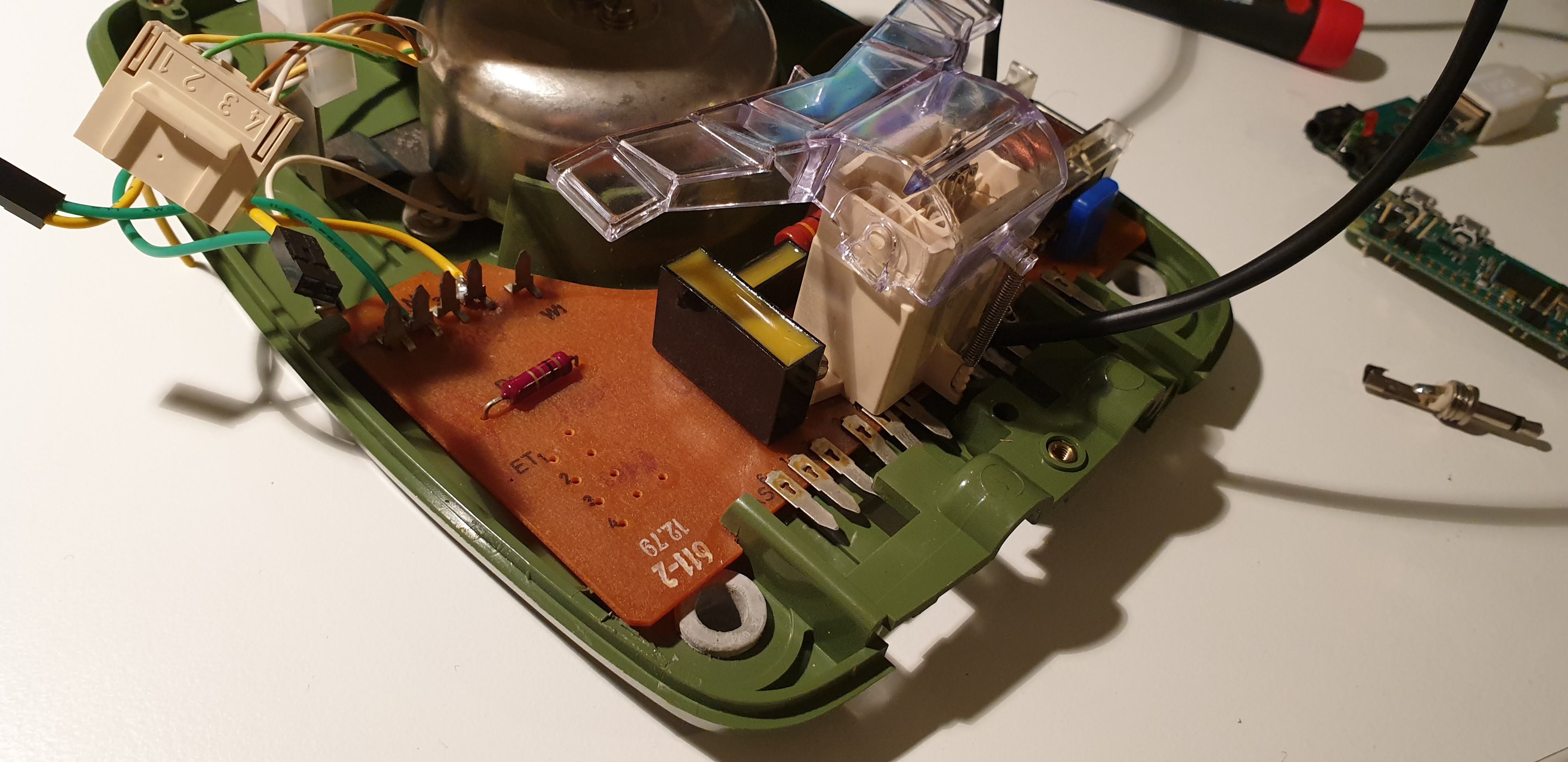
First of all, all unnecessary components have been soldered out of the circuit board to free up space for the placement of the Pi and the sound-card as well as the OTG cable linking both and additional cabling to redirect the microphone and speaker. However, the old circuit boards is a perfect support for all the pins and our devices, thus it has not been completely removed.
After checking the circuit diagram and careful cross-checking with a multimeter, the circuit between the NS pins 1 and 2 seems to close when a dial-pulse is produced. These pulses can easily be read using any input-enabled GPIO from the Pi.
Wiring the hook
The hook switch operates in the opposite way to the intuitive one. The circuit is closed as long as the receiver is hooked up and it's opened when the receiver is picked up. The circuit is opened and closed between the pins 2 and 4 of the NS header.
Because the rotary dial impulses and the hook switch share the pin 2, a voltage (or ground connection) can be fed to this pin and the value of pins 1 and 4 read using the GPIOs of the Raspberry.
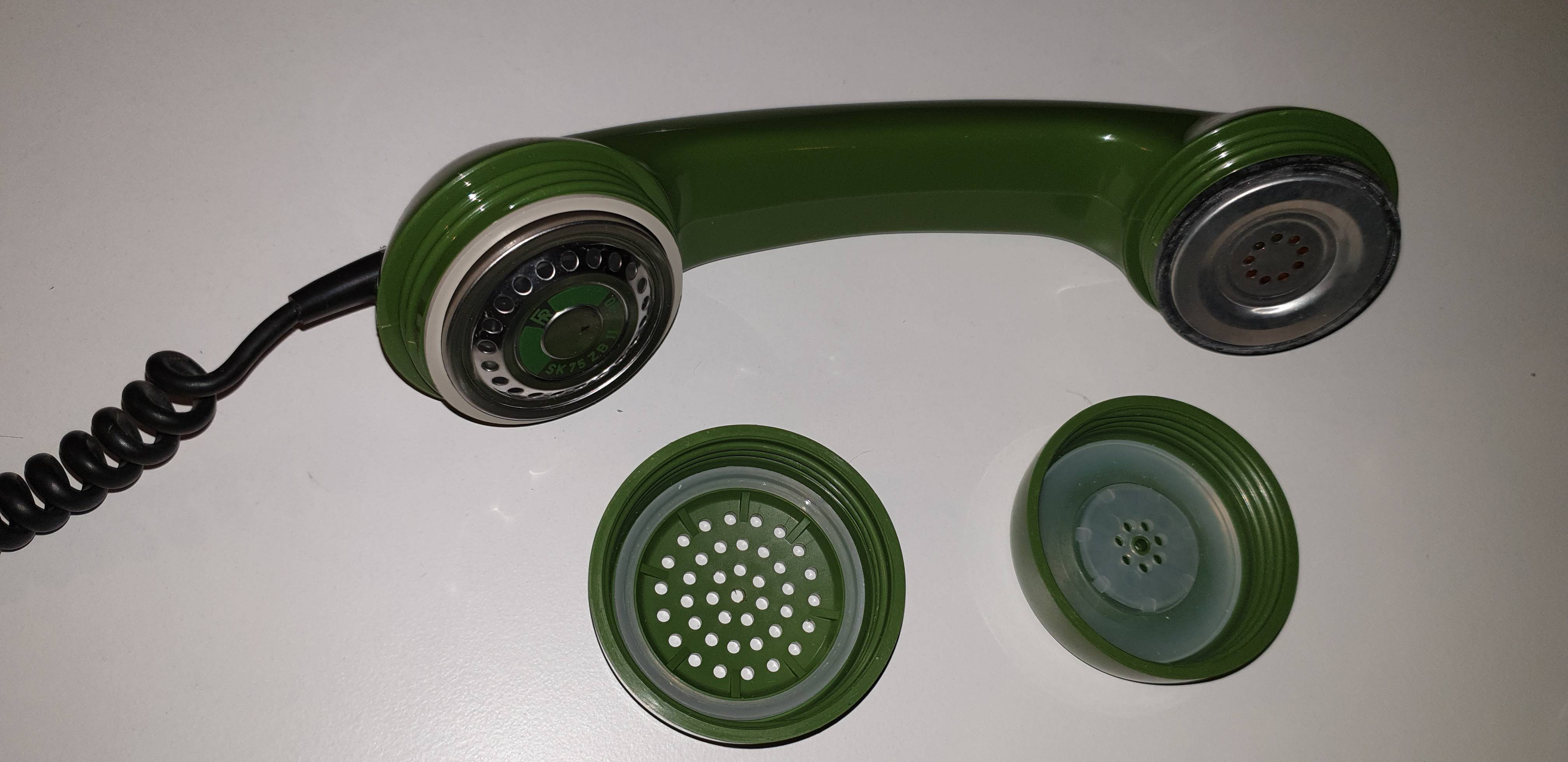
Wiring the receiver
The receiver encapsulates the carbon microphone and the speaker. The covers of them can be removed exposing both parts attached through a rubber ring which was already merged with the plastic with the pass of the years, Although the audio quality produced by both parts will not sound so great there is no real need to replace them and re-attach modern microphones and speakers as replacement.
![]()
In order not to damage the rubber rings, the wires correspond to the microphone and the ones from the speaker were found by trial and error using the sound-card. In this very model the pins 1 and 2 from the header labeled 'HS' correspond to the microphone and the pins 3 and 4 to the speaker.
![]()
Another important fact to notice is that due to the fact that the speaker and the microphone signals are mixed for transmission, there is a short circuit between their pins. Because of that, the track from the other side of the circuit board starting from speaker and microphone pins was cut to isolate them.
[insert pic of cut track]
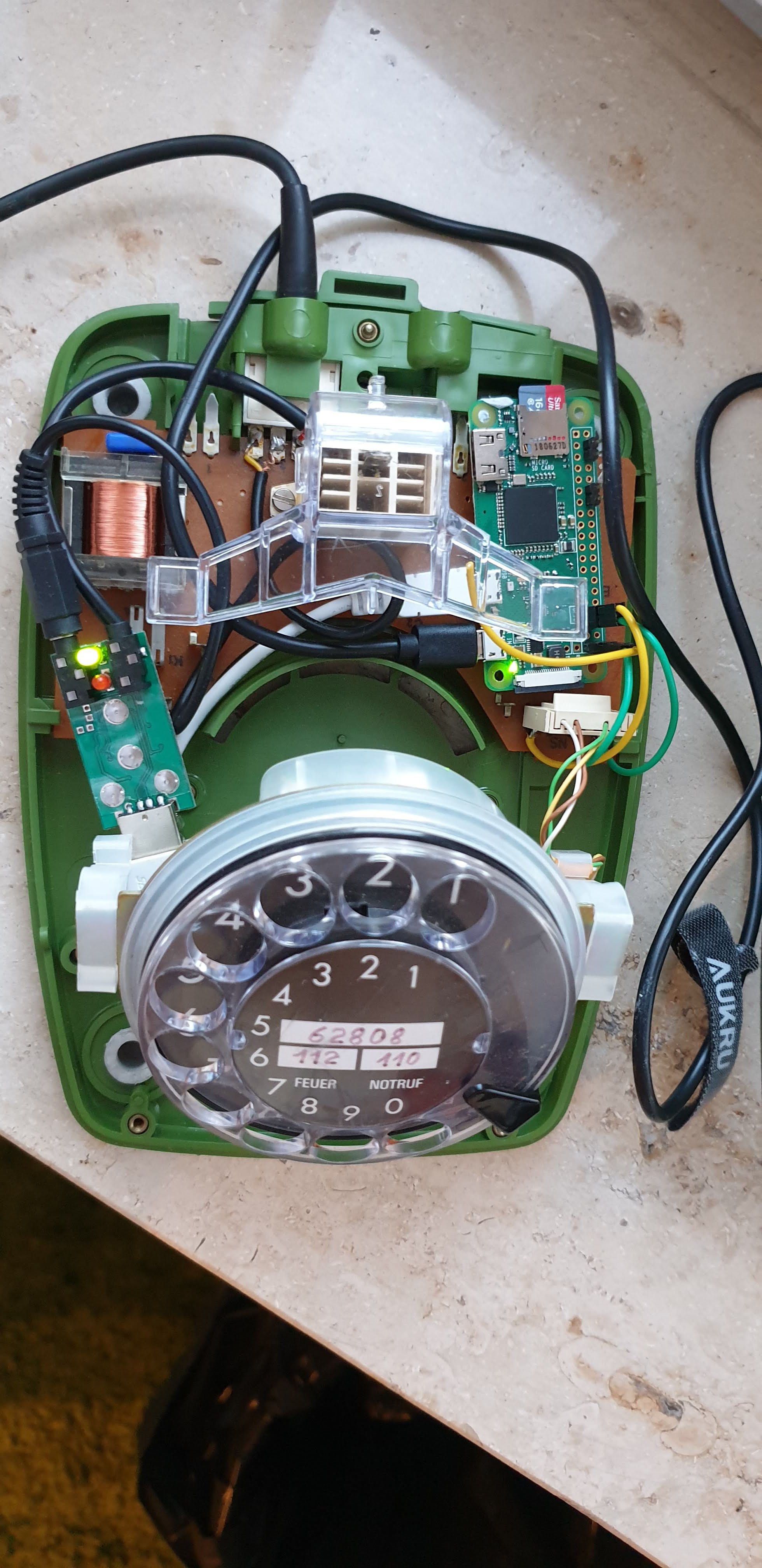
Since we cut this tracks, from this very moment the phone is nonoperational for the traditional use. The phone's net connection cable plugged to the socket branded AS can therefore be removed and discarded. There is a sealed additional socked on the very right of the connectors labelled with 'Z' which shares the pins of the speaker probably intended to connect some sort of hands-free loudspeaker. By removing its green plastic placeholder we have an ideal hole from which we can pull out our USB power cable.
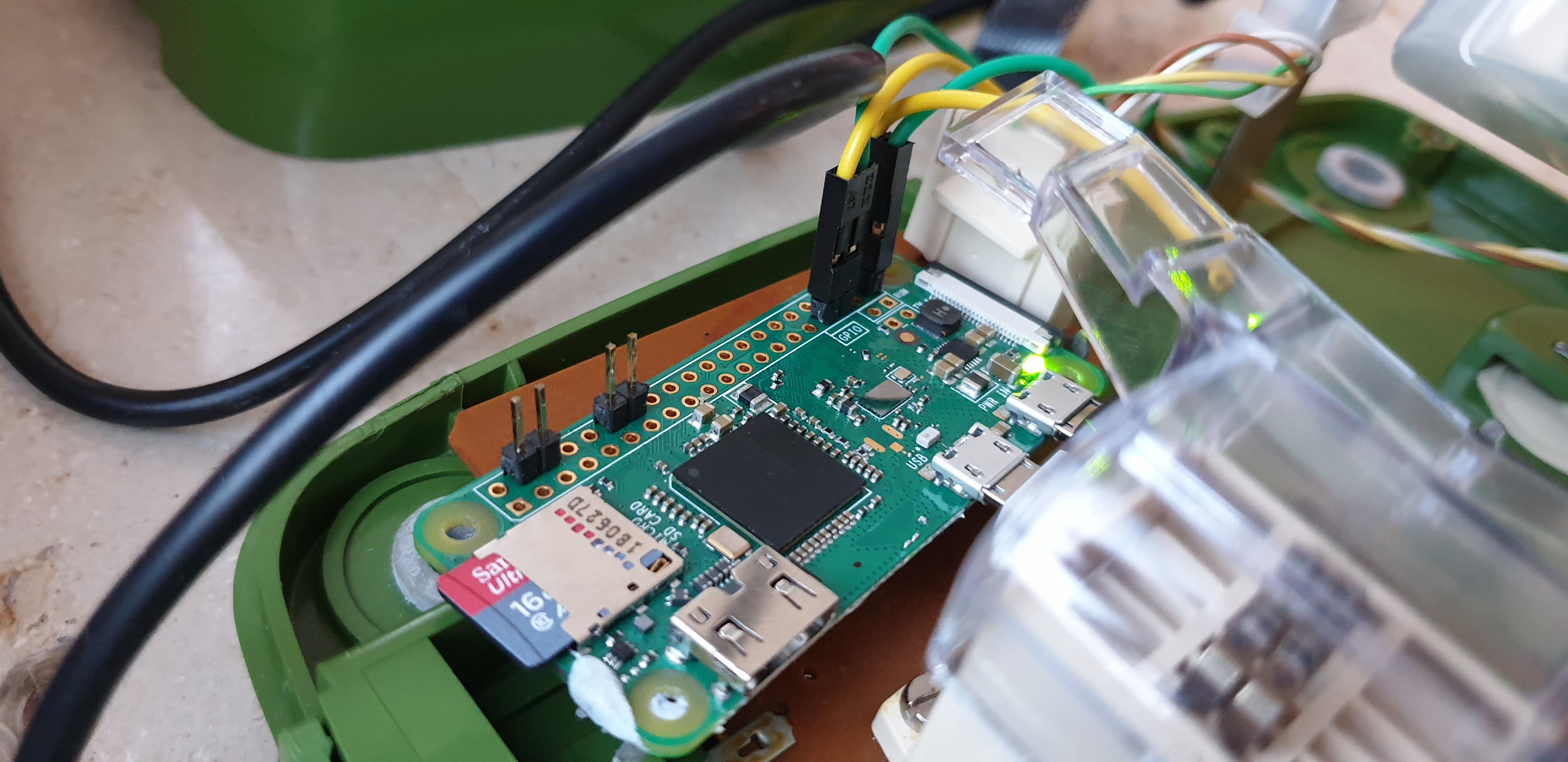
The only thing missing is to connect the sound-card, the dial and hook signals, and the power to the Pi. The final wired device looks like this:
![]()
Once the wiring is completed we can cover the phone and head to the computer for the software side of the project.
-
Opening the box and wiring
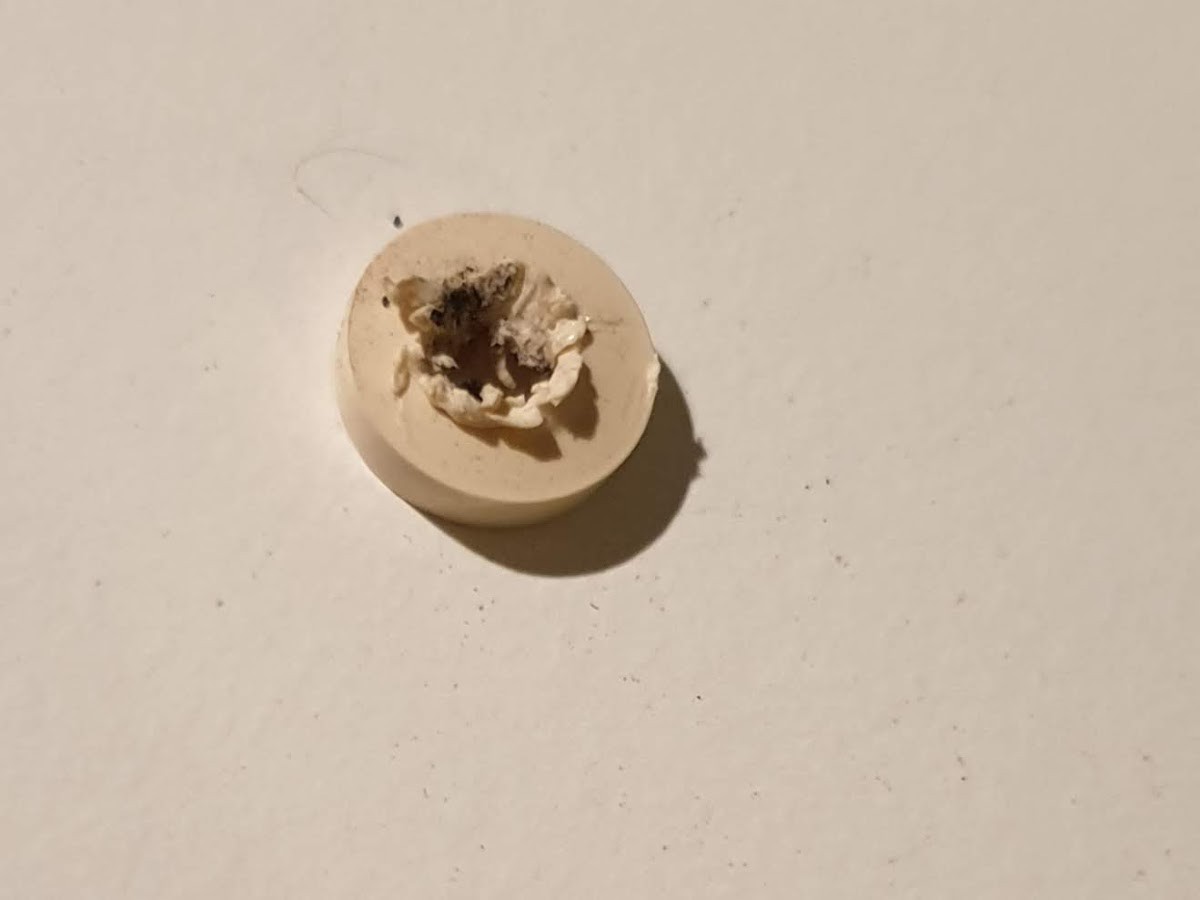
04/25/2019 at 18:56 • 0 commentsThe phone was intended to be technically manipulated only by authorized personnel of the German Postal Service therefore in first sight it does not have any exposed screws or possible means to remove the upper cover. However, there are 5 small white seals labelled with a 'D' that can be punctured and removed by using any sharp object.
![]()
Behind them 5 screws allow to remove the main cover as well as the network and receiver's wire cover. Exposing the inner part of the device:
![]()
The circuit seems to be very simple and it contains only a handful of electronic components. A quick internet search delivers us a rather low resolution circuit-diagram of the telephone:
![]()
The most meaningful components can be therefore straightforward identified and mapped to their physical locations. From the black yellow-topped diodes of the 80s to the tiny isolation transformer on the corner. Although the old electronics have an unique charm, we are only interested in the human-interface peripherals. Namely:
- The rotary dial (more on its operation later)
- The connections to the receiver (microphone and speaker)
- The hook-switch
- The ringer (more on this also later)
-
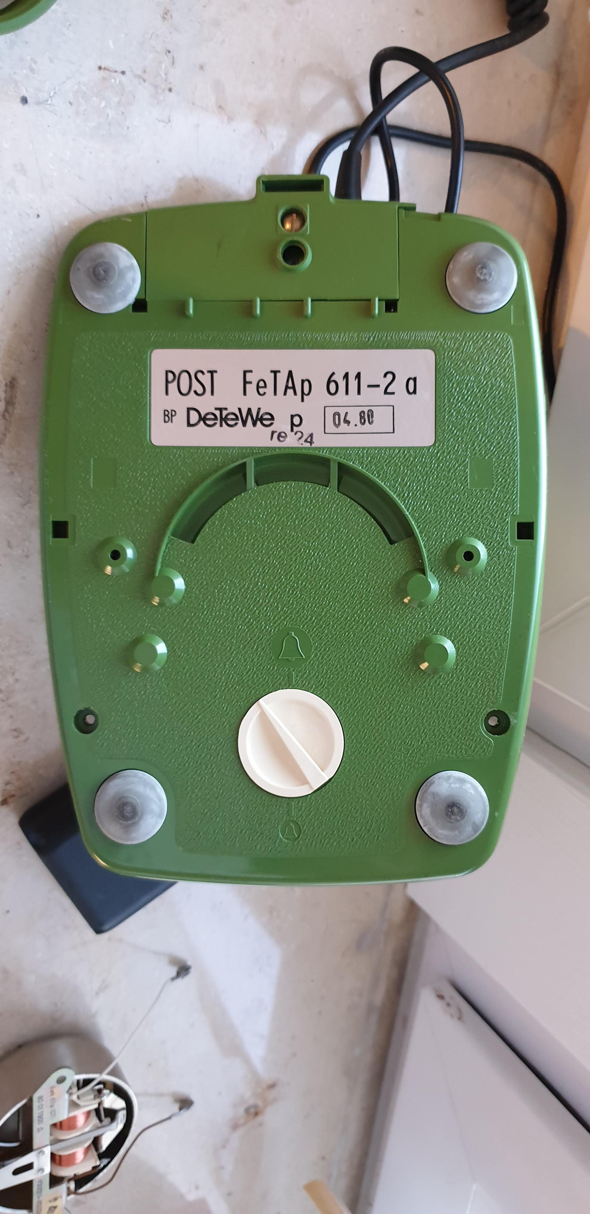
The Fernsprechtischapparat 611
04/25/2019 at 18:48 • 0 commentsGerman is such a language that allows the creation of long yet overly specific words such as the one designating the main protagonist of this project. The Fernsprechtischapparat (tabletop-telephone-machine) Model 611, appropriately abridged as FeTAp 611, was the common-issue telephone from the Bundespost (German Postal Service) starting in 1968. It allowed the real broad expansion of the German telephony network. In 1963 only 19% of German households had access to the phone network, while in 1988 already 88% of private-houses had a telephone-line.
The device that I acquired is the Model 611-2a. The digits 61 let us know that it was the rotary-dial model (as opposed to the 71 and 79 which for instance already had a numeric dial-pad). The last digit 1 informs that it is a standard model (meaning it does not include any fancy features such as return-call functionality or a fare counter). The final 2a presumably shows that it is a later model.
On the same plate, the number 04/80 is engraved inside a black box pointing out to the date of issue of the terminal (April of 1980).
![]()
An old rotary phone as Bluetooth set
When did the charm of holding a bulky receiver to your ear end? What if we could bring the feel of the old times to our smartphones?

/Year_5/ELC-523-Advanced%20Communication%20Systems/Telephone_Instruments/Images/Pulse_Train.GIF)