Yann Guidon / YGDES
-
Another fork
03/14/2017 at 05:39 • 0 commentsThe 16-segments module project now has its own page : #dual-mode 16-segments LED display module !
All the new discussions will happen there now. -
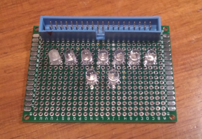
Raspberry Pi educational boards
02/21/2017 at 05:58 • 3 commentsDuring the training at IESA Multimedia, student projects need boards to learn how to control inputs and outputs.
I designed 5 boards:
Rainbow board
Just a fancy board with 9 LEDs of different colors
Used with #micro HTTP server in C by #hammer's smashing game - Rasberry Pi
![]()
![]()
ROUGE : GPIO4
ORANGE : GPIO5
VERT_JAUNE : GPIO6
VERT : GPIO7
VERT OCEAN : GPIO8
BLEU : GPIO9
UV : GPIO10
BLANC : GPIO11
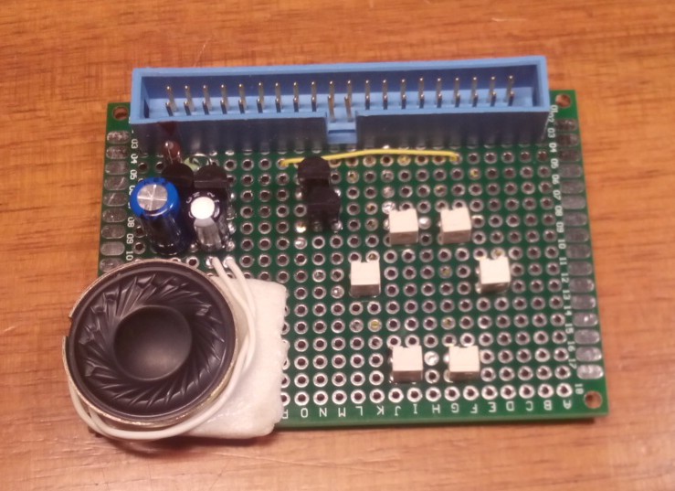
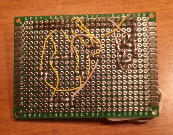
ROSE : GPIO12Car board
For simulations of a car's remote control
![]()
![]()
Throttle (HP) : GPIO18 (can use PWM)
Right : GPIO5
Left : GPIO6
Backwards : GPIO7
Forward : GPIO8Some bash code implements the roundabout pattern:
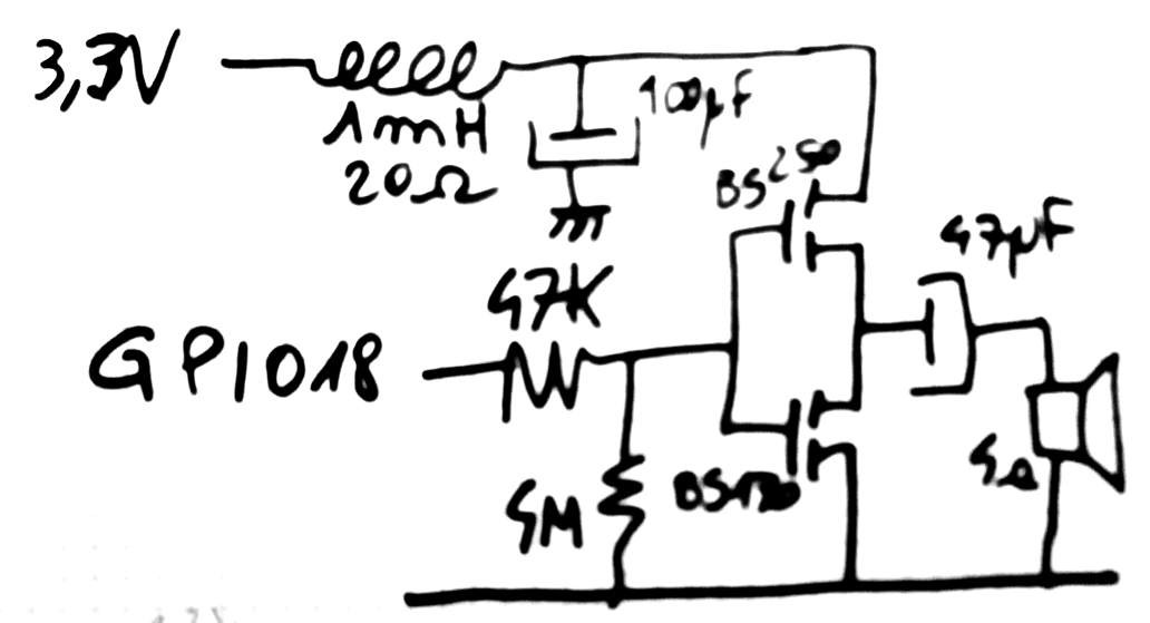
while  true
do

sleep 0.5
./GPIO_on.sh 6
./GPIO_off.sh 7

sleep 0.5
./GPIO_on.sh 8
./GPIO_off.sh 6

sleep 0.5
./GPIO_on.sh 5
./GPIO_off.sh 8

sleep 0.5
./GPIO_on.sh 7
./GPIO_off.sh 5

done
The throttle output is actually connected to a dirty amplifier that drives a miniature 4 Ohms loudspeaker. No crazy magic here but I used a crude discrete CMOS amplifier (BS170 and BS250, as used in other projects) with an input resistor to reduce the bandwidth. A LC network (with L having significan R) keeps the current draw low depending on the binary signal's frequency.
![]()
Some dirty code makes it vibrate:
while  true
do
./GPIO_on.sh 18
./GPIO_off.sh 18
done
(the GPIO scripts are provided by #C GPIO library for Raspberry Pi )LED board
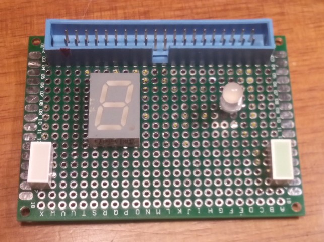
Just a few miscelaneous LED (a red block, a green block, a RGB LED (inverted polarity !) and a 7-segments (and dot) module.
![]()
RED : GPIO14
GREEN : GPIO15RGB_R : GPIO19 (inverted!)
RGB_G : GPIO20 (inverted!)
RGB_B : GPIO21 (inverted!)7SEG_A : GPIO4
7SEG_B : GPIO5
7SEG_C : GPIO6
7SEG_D : GPIO7
7SEG_E : GPIO8
7SEG_F : GPIO9 (assignation: to be determined)
7SEG_G : GPIO10
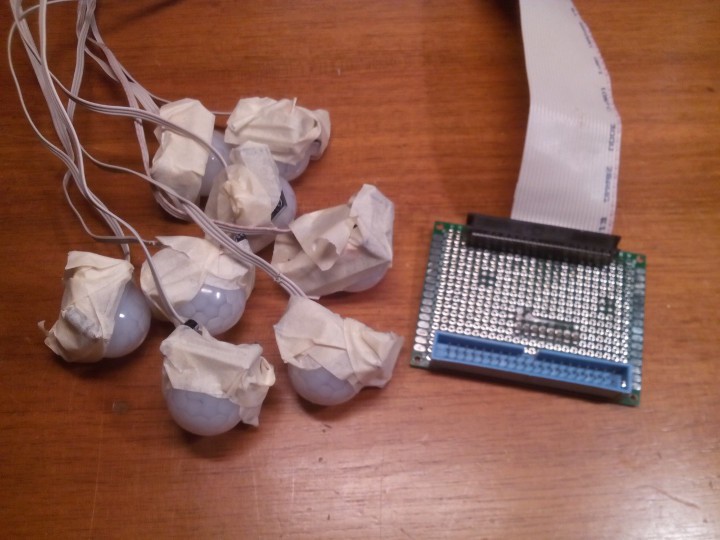
7SEG_H : GPIO11PIR board
8 inputs triggered by passive infrared motion detectors.
See http://www.azaryia.com/ for one project that uses it.
![]()
![]()
![]()
PIR1 : GPIO5
PIR2 : GPIO6
PIR3 : GPIO7
PIR4 : GPIO8
PIR5 : GPIO9
PIR6 : GPIO10
PIR7 : GPIO11
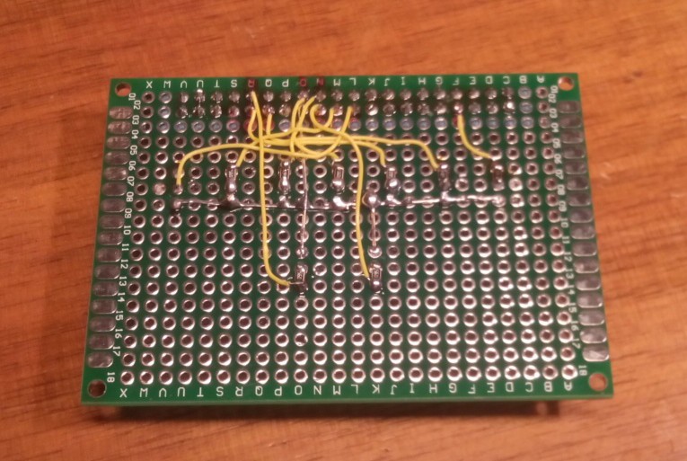
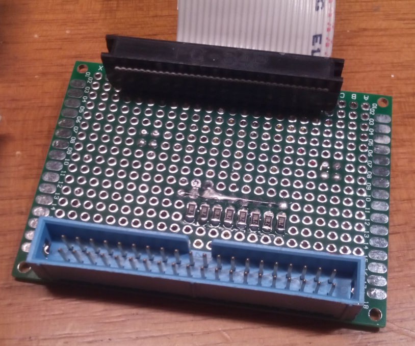
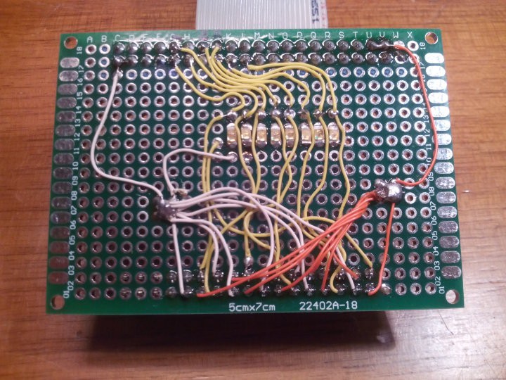
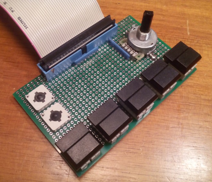
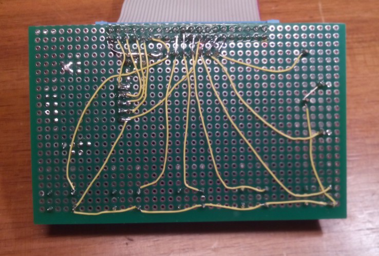
PIR8 : GPIO12Buttons board
For dealing with simple inputs.
Used with node.js for the sampling sequencer at https://github.com/luberlu/bloopController
![]()
![]()
A1 : GPIO17
A2 : GPIO27B1 : GPIO22
B2 : GPIO10
B3 : GPIO9
B4 : GPIO11
B5 : GPIO5Hexadecimal coding wheel :
1 : GPIO6
2 : GPIO13
4 : GPIO19
8 : GPIO26.
-
Getting our hands dirty at last
01/19/2017 at 01:12 • 0 comments(20170118)
The character display project requires many red LEDs so I brought some.
Like, I dusted off my stock and brought whatever reference where I have a few thousands... Don't people LOVE LEDs ? :-D
I also checked my stock for 74HC595 : 120pcs (from another failed display project) is just enough for this project, niiiiiice.
But the LEDs and the driver have intricate electrical interactions that we have to prevent by testing, measuring, The 74HC595 is not a "power driver" : per the datasheets, the absolute maximum current per data output pin is 35mA, and the current must not exceed 70mA on the ground pin or the +Vcc pin.
http://www.nxp.com/documents/data_sheet/74HC_HCT595.pdf
One consequence : because of the 70mA limit, we can ensure that the board consumes at most 70×2=150mA per display. Under 5V, that's 750mW max. If you want 20 letters, get a 20 Watts power supply and you're done.
Since there are 8 outputs, each can at most supply about 70/8=8mA per pin to the respective segment. But it's a very conservative estimate.
- This can be relaxed a bit because there are 14 segments, so each 595 can drive only 7 segments. That means each segment can draw 70/7=10mA.
- Some segments have fewer LEDs so the individual LED current can be increased a bit as well. If a pair of LED draws 4mA,
- 4-LEDs segments draw 8mA
- 6-LEDs segments draw 12mA - Not all segments are energised at the same time.
- Overall current can also be increased by switching some LEDs to 0V, others to 5V. That's a naughty trick because the circuit needs a reliable potential reference and this decreases the signal integrity... Because of this, it's better to switch the "high side" to keep the ground pin "quiet" and avoid ground bounces or switching noise there.
- The 595 has internal losses, the 5V supply can also decrease due to the resistance of long wires, so the current of the LED should be calculated for a 4.5V supply.
Anyway the point is to design a text scroller, not a lighting fixture :-)
The most fun part of the day, however, is selecting which LED reference to use for the rest of the project. I've brought several types :
- Amber LED (about 4K) in PLCC2 : too hard to solder for kids
- Dark red 5mm LED (1K) : too dim
- Old (1997) 3mm flat top round LED (about 4500pcs) : OK but not as visible as the others
- SMD type (3 reels of 1500) : nice but hard to solder
- flat-top, diffused 5mm (without ring) : Good diffusion and brighter but only 1500pc available
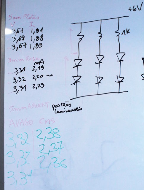
![]()
The test systems were : 3 parallel strings of 2 LEDs and one 1K resistor, powered by a Lithium battery (6V). This allows the simultaneous measurement of the current and voltage and compare the performances.
- The flat-top diffused 5mm LED have good light output but work at a higher voltage (1.85V), which could limit their use.
- The 3mm "pink" flat-top, and the Avago SMT, have a lower operating voltage (1.65V) but less diffusion, they are more "dotty". An additional diffusion layer might be required.
![]()
The jury is still out on which of these to choose.
The "flat top" is alluring but it will not be possible to make strings with 3 LEDs in series. OTOH, a string of 3 older 3mm and the Avago SMT LEDs draws about 2mA under 5V.
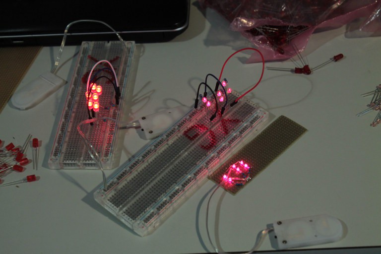
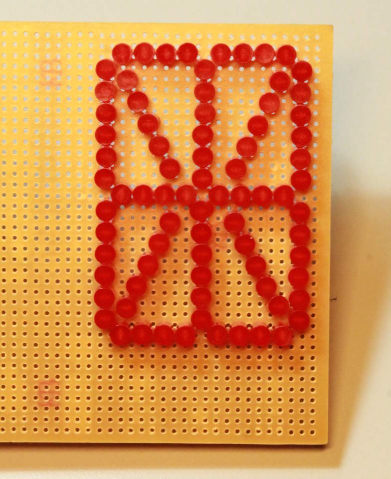
The LEDs are nice, but the placement matters a lot too. So we used standard predrilled prototyping boards to arrange and see how it would look in reality.
![]()
We used 5mm (collarless) LEDs because 3mm LEDs can fit but not vice versa.
The long/vertical segments use 6 LEDs, the short horizontal segments use 4 LEDs, but the pitch made it hard to fit 6 LEDs in the diagonal segments. 5 LEDs is a problematic number because it does not let us create nice pairs of LEDs.
![]()
Hopefully, the final PCB will allow us to make a slightly denser diagonal with 6 LEDs because they will not be forced into a fixed grid. Pythagora's theorem says that we should ideally be able to fit 7.2 LEDs in the diagonal but there are subtle details that reduce this number.
For the first prototype, we count 80 LEDs (84 if we manage to have 6 LEDs per diagonal). That means 40 resistors, as well...
Some room must be left free for the driving circuitry (DIPswitches and shift registers).
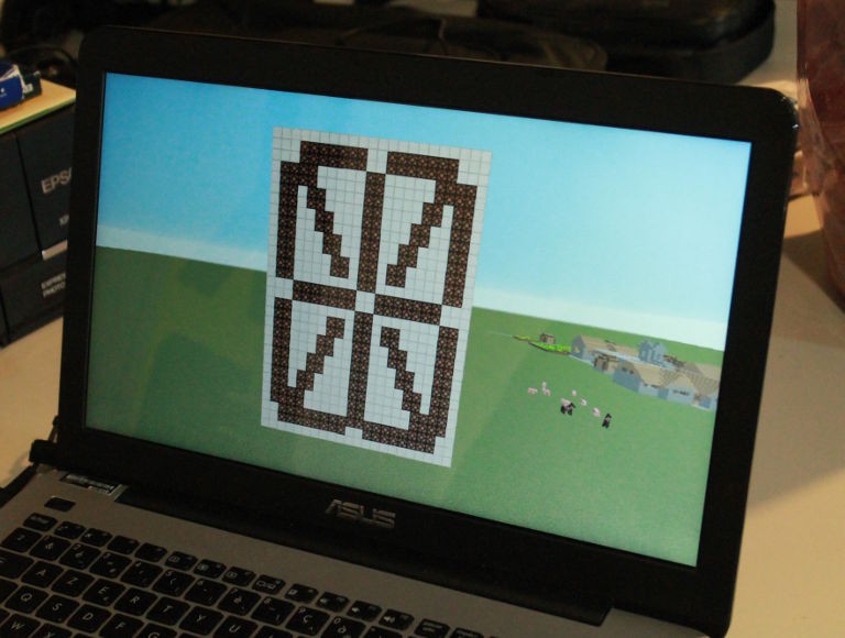
Meanwhile, Adam is already preparing a virtual mock-up with Minecraft...
![]()
I guess it will be finished long before our material circuits :-D
About the resistors :
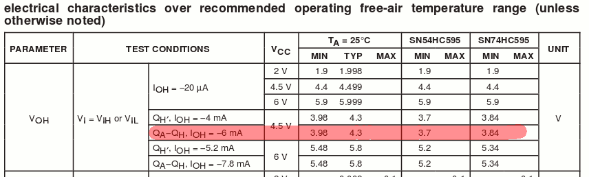
Reading https://www.sparkfun.com/datasheets/IC/SN74HC595.pdf I find the following data:
![]()
The output pins have their own significant impendance and the voltage drops near our LED's level when there is sufficient load. The drop ranges from 0.2V to 0.6V... Balancing between the strings requires some resistance, probably 50 to 100 ohms, the value is to be determined with experiments before ordering the suitable resistors.
Note for later : request a black varnish for the final PCB, to increase the contrast.
-
The dawn of a new project
01/16/2017 at 22:50 • 2 comments2017 is here !
I haven't kept up with the latest logs, shame on me, but there is a bit of progression.
Now, we embark on a 3-months period (10 workshops) where we are asked to design and build a project.
- it must be participative and inclusive so kids and others can come and go easily without breaking the project
- it must be easy but not too trivial.
- it must be useful, add something to the workshop's room for example
- from there, it must be modular, made of many identical pieces
We have brainstormed and chosen the following project :
make many modules, each module writes a letter with 14 segments made of LEDs, modules can be chained to create words
The letter is selected either with DIP switches or an external digital control (hooked to a Pi for example). This dual-mode ensures that no programming is required for testing the board or making the first applications. Later, when digital control and programming are understood, the boards will be easy to chain and create scrolling boards !
So the first workshop started with a brainstorm session that led to this outline, but is it possible and realistic ? We spent the rest of the workshop examining some of the salient aspects.
First, the PCB should be bound to the 10×10cm cheap PCB (made by dangerousprototypes and others). So a letter is approx. 10cm high and 7cm wide.
From there, we determined that there would be about 92 LEDs per letter ! There are 10 long segments of 6 LEDs and 4 (6?) segments of 4 LEDs. If we build 50 letters, that's almost 5000 LEDs to solder !
Another consideration comes from the requirement to run the circuit with digital inputs : the letters are powered from 5V. This creates a number of consequences for the circuit's organisation.
The segments having either 4 or 6 LED in series, under 5V, it seems appropriate to use LEDs in pairs, to make 2 or 3 parallel strings per segment, with a current-limiting resistor.
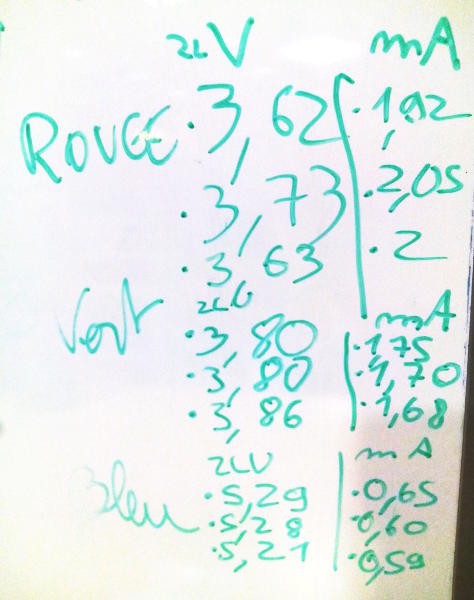
We did a few experiments with the LEDs we had lying around. Several colors (red, green and blue) were tested for electrical and visual properties.
A 1K resistor and two LED are wired in series then powered with a couple of CR2032 batteries (6V).
![]()
- The blue LED draw little current (0.6mA only) but require a significant voltage (2.75V) which makes it hard to use 5V. Without resistor, there is probably too much visual variations, and the available 5V/2LED=2.5V (give or take 10% due to possible wire attenuation) is not enough for a visible dot.
- The green LED are a bit faint, compared to others, and draw more current (1.9V@1.7mA). I noticed that the CR2032's voltage dropped significantly, unlike the other tested colors.
- We selected the red LED because they are visible yet don't draw much power (1.85V@2mA).
Tomorrow, we'll test which type/model of LED is best suited, from my personal stock...
Control : the segments are driven either by a DIP Switch or a 74HC circuit. The 74HC circuit is disabled when the DIPswitch is active, with the "output enable" pin.
The boards are chained so they have an input and output bus.
The original idea was to have a couple of 74HC574 to latch 16 bits but the wide bus was too cumbersome.
I have enough 74HC595 to replace this, so a serial / SPI interface will be used.
It's interesting because we'll learn about the shift registers...
-
More diodes, charge pumps and MOSFETs
11/17/2016 at 22:17 • 13 comments20161116:
Just to be sure the kids understand, and to help one kid who was sick last time, let's redo the charge pump expermient. This time, with screenshots and more bugs.
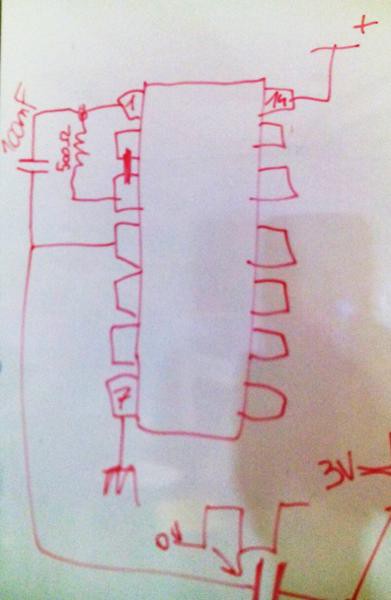
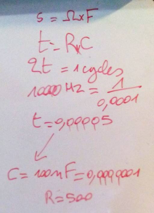
Let's start with the oscillators : the classic 74HC04 provides 2 inverters, then we hook a resistor and a capacitor. By now, the kids should do this circuit without any difficulty :-)
![]()
What are their value ? I have set the goal to 10KHz. A previous workshop has shown that the frequency is about 1/2RC and we have C=100nF. Let's compute the resistance...
![]()
Some whiteboarding later, I come up with 500 Ohms. I can find 510 ohms in my stash of resistors so let's go. We get about 8KHz, that's -20% of the goal but pretty close, considering the other unknowns.
There's a problem though : of the 3 circuits that were assembled, 2 showed problems as they would not oscillate. The reason is not clear, bad capacitor ? Maybe a too low resistance ? (I don't have smaller capacitors at hand)
The behaviour is odd, as the scope shows a small burst of activity then the trace turns flat, mid-point between 0V and 3V.
So we focus on the only circuit that seems to work.
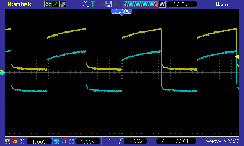
We connect a 1µF ceramic capacitor to the output and connect the other electrode to the scope probe.
![]()
The blue trace is initially a copy of the original yellow square wave but it quickly drifts (in about one second) toward -1.5V/+1/5V
This is explained by the capacitance of the scope probe: 1µF × 1M Ohms = 1second
Cue in discussion about low-pass, high-pass, time constants and what if we set the probe impedance to the 10× mode :-)
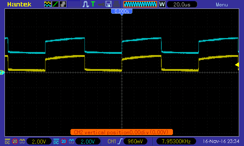
Then let's introduce a diode : current passes in one direction but not another. Tthe diode is connected to the +3V rail and the passing direction is outward the rail.
![]() The trace has shifted upwards, the capacitor's electrode is at a higher mean voltage than the power supply.
The trace has shifted upwards, the capacitor's electrode is at a higher mean voltage than the power supply.Now, let's see with the diode connected to 0V:
![]()
The waveform has shifted below 0V, but there is still a part that reaches 0.7V, which is the "drop" of the diode. The output voltage now reaches -3V +.7= -2.3V (this was not apparent in the previous ss because of a bad setting of the 0V level)
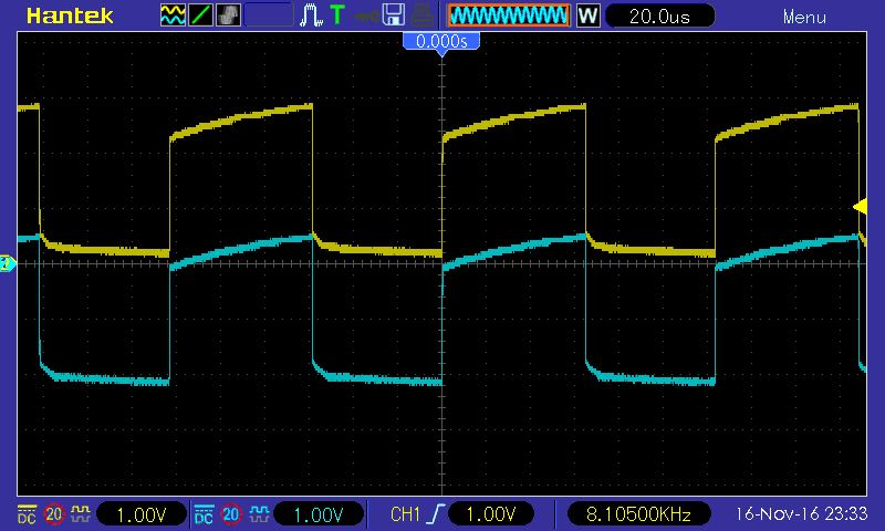
Now, let's add the 2nd diode and a large capacitor. Oooops, it seems to overload the 74HC04 which stops working, so let's use only 1µF.
We measure the generated voltage : with a step-up configuration and 1µF, that's 4.74V. When adding a 150K resistor load in parallel with the filter capacitor, that's 4.54V, or a 200mV drop. From there we can calculate the impedance of the generator and estimate the drop with other loads (approx 1mV/Kohms, or 1M Ohms of impedance...)
![]()
It's not efficient, but advantageous to generate very high voltage when cascaded.
Discussions about diodes lead to other applications, in particular the antique keyboards, and diode matrix ROM (oh, wait, a common subject these days :-D)
From there, how does one creates a diode ROM ? It's a matter of decoding. What can it be used for ? Let's say, a 7-segments decoder :-)
![]()
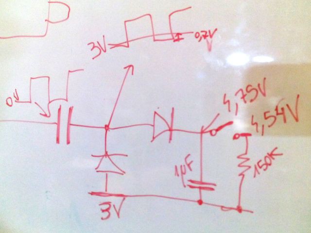
How does one decode the ROM ? it's another matrix, but with AND gates this time. Very easy to design on Minecraft, once you know how to copy-paste an element :-D
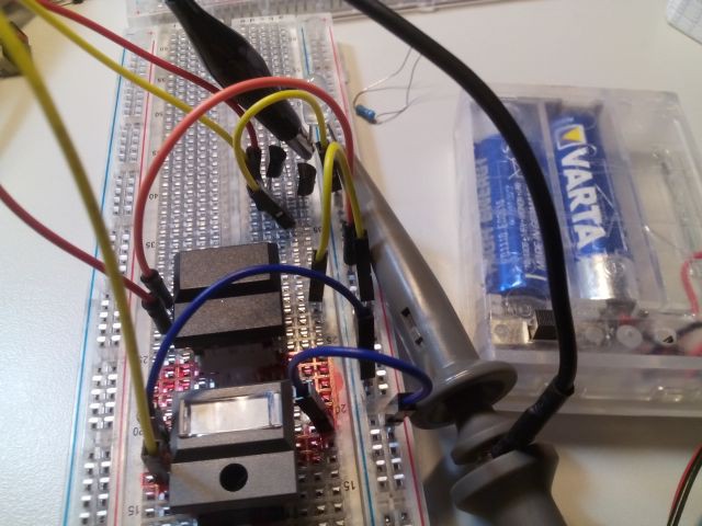
Back to the proto boards and actual (N)AND gates. The simple N-MOS inverter is shown again, and a second transistor is added to prevent it from conducting current to 0V : that's how we make a NAND.
![]()
If the transistors are in parallel, it's a NOR.
Considerations about complementary MOS circuits are discussed : less power draw, faster, but at this time we're happy with a pull-up resistor. We measure the rise time (when the button is released) at about 400ns : that's slow but we don't need to run at Megahertz speeds...
![]()
-
Diodes, charge pumps and MOSFETs
11/10/2016 at 01:44 • 0 commentsToday's workshop started by a reminder of the basic inverter-based oscillator. I wanted to see if the kids remembered how to wire it, but I mostly wanted to use it as a customisable signal generator.
Then added a 1µ capacitor at the output, connected to nothing. The 'scope shows the square wave, that shifts toward 0V average because of the probe's impedance.
Then a diode is added to "force" the shift the square wave below 0V or above Vcc.
It's not really interesting so we add a second diode, to keep the square wave from "going backwards", then a capacitor to store the energy.
Voilà ! a charge pump !
It's one of the practical methods that can be used to generate small currents beyond the normal range of the power supply.
Then after the diodes, finally the transistors. The MOSFET is shown and the BS170 is presented and measured.
The BS170 is a sort of voltage-controlled resistor, but it has other characteristics and two "parasites" : capacitance and diode. They are explained then used to determine the pinout.
Then a basic application circuit is shown: a potentiometer generates a control voltage between 0V and 3V (connected to the gate), the MOSFET's source is connected to 0V and the drain is connected to the +3V through a white LED.
Turning the pot changes the voltage and we see that the LED starts to glow at about 2V.
There, you have an "inverting logic gate", which is actually one half of the 74HC04N we had used so far.
A RC network is added between the gate and the pot's brush signal. 1M ohms in series, then 1µF in parallel (between the gate and the source). Turning the pot is still effective but with one second of delay (in one direction).
When we replicate this circuit, we have a longer string, with more delay. With 3 stages, either 1 or 2 LEDs are glowing (don't forget the pull-up resistor).
When the pot is replaced by a wire coming from the end of the string, we end up with the circuit of the #Yet Another Electronic Lampyridae
We see what happens when only 2 stages are looped, even number=>stable (memory cell), odd number=> unstable (oscillating)
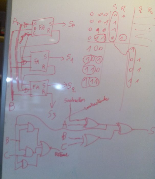
After the electronics, it's Minecraft time. The Redstone system is used and the discussion quickly drifts toward how to design a binary adder. We discuss about half-adders, full-adders, cascading the carry bit then how to perform subtraction...
From the expected outputs, we derive the equations and the logic diagram, that Adam implements in Redstone logic.
![]()
We start to think about how one Redstone element translates into actual electrical parts. For example, we favor OR gates because they are "free" in Redstone (just wire everything in parallel)
Electronics Workshops Resources
Project where I put logs and other useful informations from past workshops
 The trace has shifted upwards, the capacitor's electrode is at a higher mean voltage than the power supply.