-
11Main PCB Prep
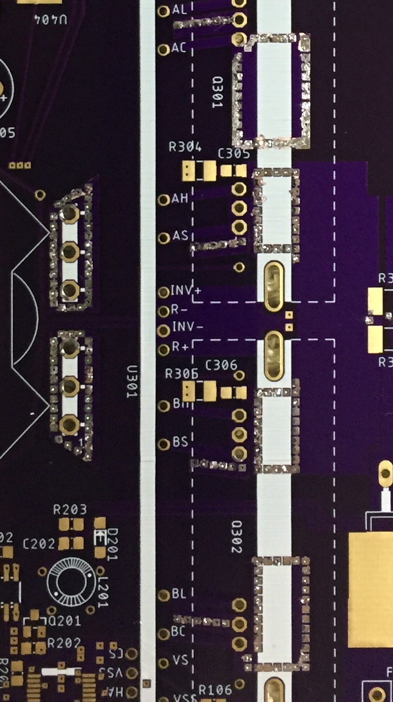
Before assembling the main board it's a good idea to fill (solder) all the vias connecting the power planes in the inverter section. This reduces losses and improves dissipation.
![]()
-
12Machining the Case
The case is extruded aluminum, 203mm L x 144mm W x 68mm H. Purchased on eBay and I believe they are regularly available.
For everything I have on my electronics bench I lack in machine shop tools, basically a hand drill and Dremel. The files section has cutout patterns drawn in Eagle that you could use for a drill / route stencil. Annotations & additional instructions are placed on the Tdocu layer.
Some of the extrusions on the front inside of the top half need to be removed. One is to allow for proper fit of the outlet and the other is for the fan. Both are annotated on the Eagle 'PCB'.
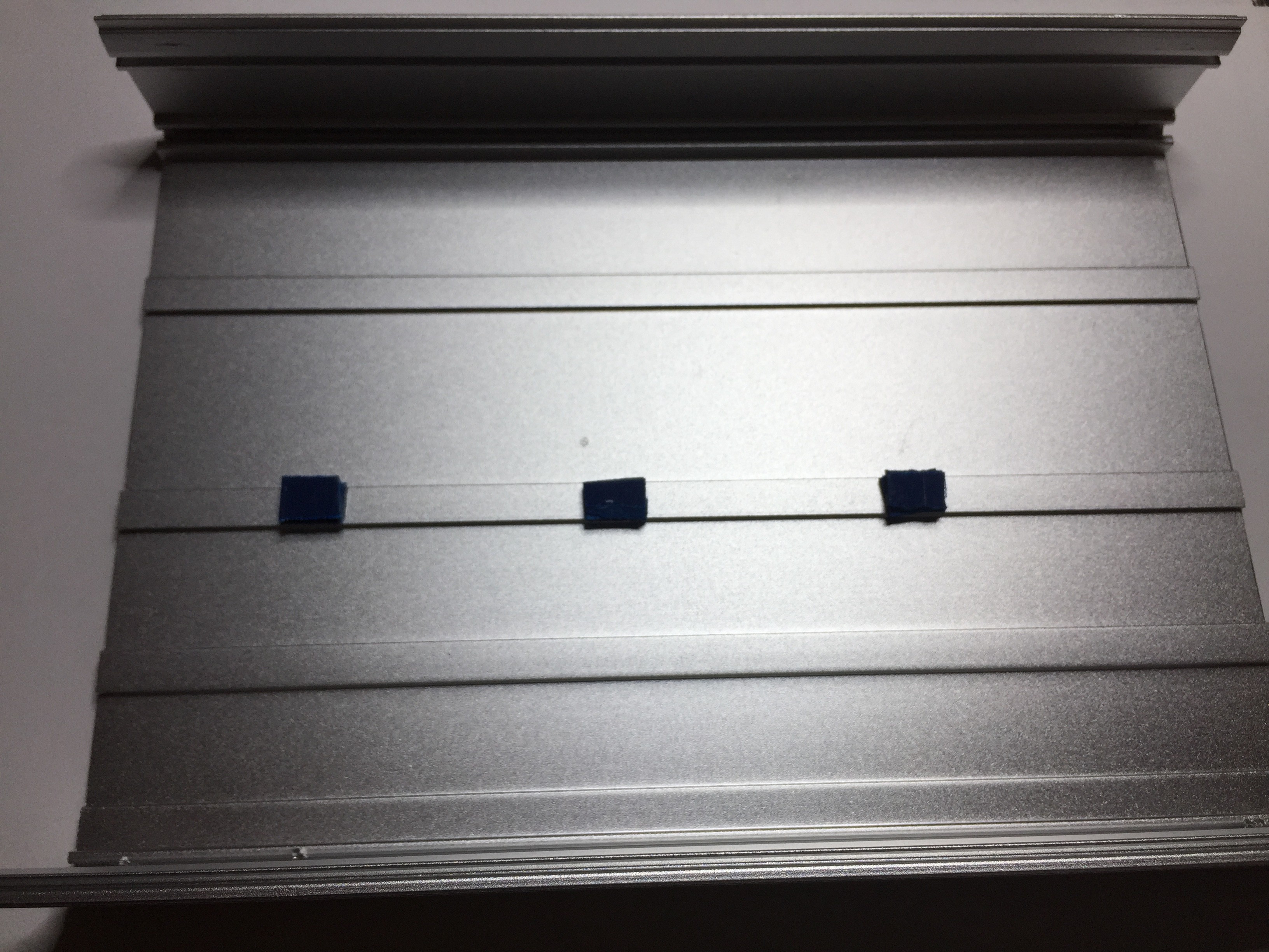
It is also a good idea to install supports for the PCB, particularly if it is 30mil. The picture below shows three supports placed on the center rib of the inside bottom case. They are made of two blocks of 60mil FR4 glued together. Make sure all copper is removed.
![]()
Last, the PCB mounting holes are positioned for securing to the case with sheet metal screws that use the corner flange. Unfortunately it is uneven so care must be taken when tightening to prevent distortion or damage to the PCB. It is possible to drive the screw in perpendicular thru careful positioning of the screwdriver; a drill press would do a better job of setting perpendicular threads for a machine screw.
-
13Compiling Controller Code
Both the main and sine controllers are compiled using XC8's 'Pro' mode. Performance has not been profiled in 'Free' mode. Both employ PD algorithms that are dependent on run loop execution time, so performance may be adversely affected.


Discussions
Become a Hackaday.io Member
Create an account to leave a comment. Already have an account? Log In.