-
RC1 (release candidate 1)
10/03/2019 at 05:34 • 0 commentsFeature complete and code complete. No apparent glitches. Testing time...
https://gitlab.com/arduinoenigma/megaenigma
http://people.physik.hu-berlin.de/~palloks/js/enigma/enigma-u_v25_en.html
-
Lots of Progress
09/24/2019 at 04:16 • 2 commentsThe universal enigma engine seems to be working correctly
Here are a couple of posts with the current project status:
![]()
![]()
https://www.instagram.com/p/B2dJO-4n6Dr/
-
The State of Both Machines
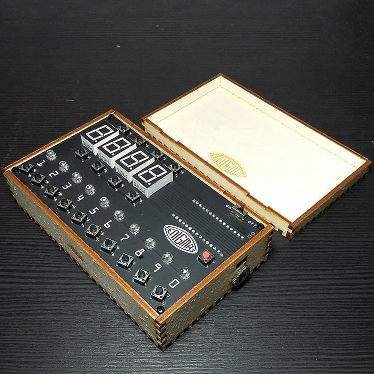
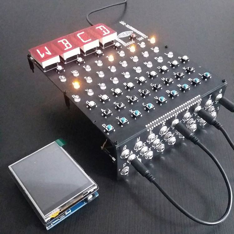
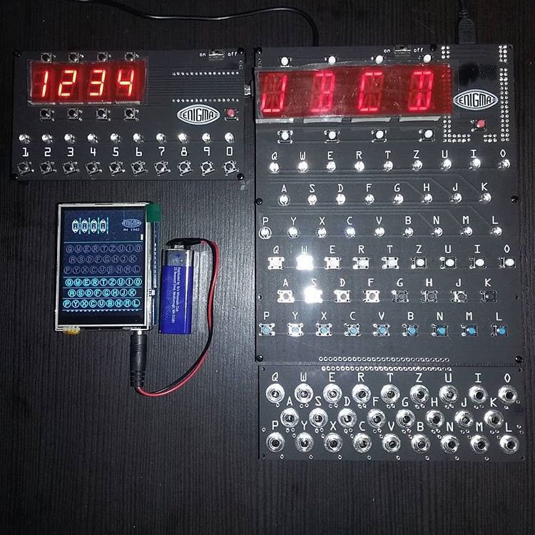
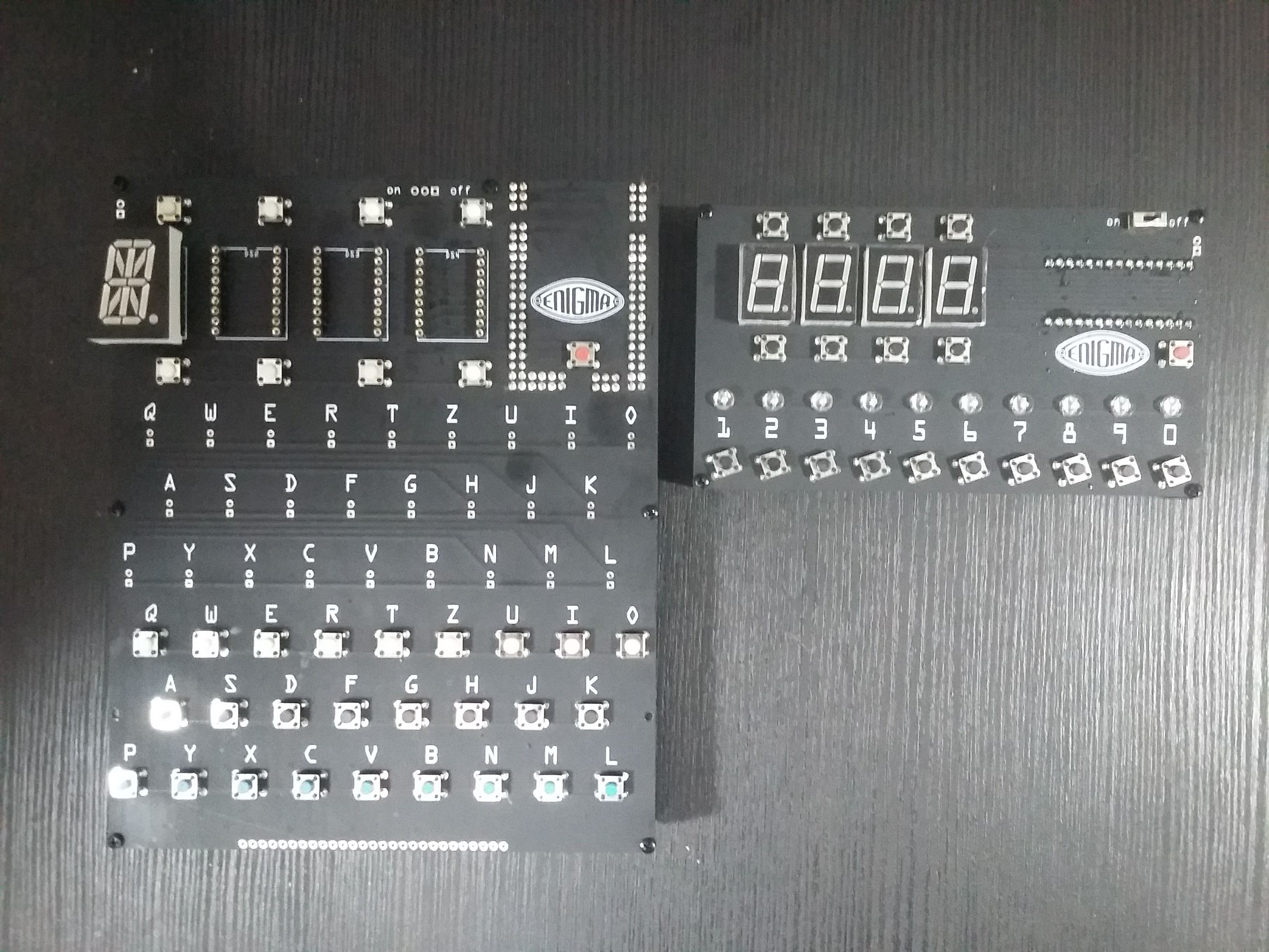
07/28/2019 at 17:07 • 0 commentsCurrent pictures of the machines:
![]()
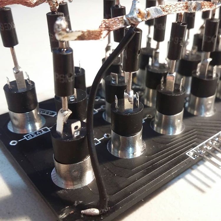
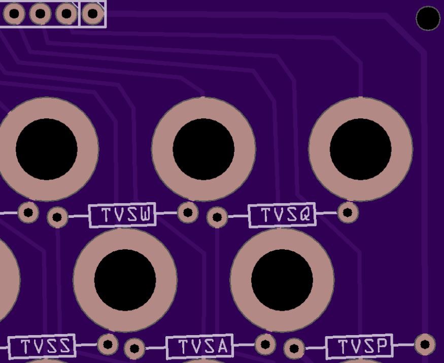
This is how I ended up doing the Transient Voltage Suppression (TVS) Diodes since the legs were a little wider than the holes on the board.
![]()
![]()
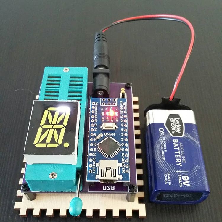
And a little bit of Yak shaving. This is a programmable tester to make sure the LED display modules are not defective, custom made for this project.
![]()
-
Shopping List
06/16/2019 at 05:51 • 0 commentsMega:
Mini Meduino Mega 2560 R3 Board Pro Mini ATMEGA16U2 with Male header for Arduino
https://www.ebay.com/sch/i.html?_nkw=Mega2560+Pro+Mini+ATMEGA16U2+-ch340g
0.8" 0.8in 16 Segments display 27.7x20mm 0.8 inch
https://www.aliexpress.com/wholesale?SearchText=0.8"+0.8in+16+Segments+display+27.7x20mm+0.8+inchPlugboard:
10 3.5mm Female Stereo Audio Jack Connector panel mount
https://www.ebay.com/sch/i.html?_nkw=10PCS+3.5mm+Female+Stereo+Audio+Jack+Connector+panel+mount10 6" 3.5mm Synth Patch CABLE black
https://www.ebay.com/sch/i.html?_nkw=10+6"+3.5mm+Synth+Patch+CABLE+blackP6KE6.8 TVS DIODE
https://www.ebay.com/sch/i.html?_nkw=+P6KE6.8+TVS+DIODE-connect ground (left pin) on plugboard to ground (left pin) on main board with a 1K resistor in case a patch cable touches the jack and the ground pin of a TVS, the pin is not shorted to ground.
Z30:
arduino nano v3
https://www.ebay.com/sch/i.html?_nkw=arduino+nano+v3
0.56" 7 Segment LED Display Common cathode
https://www.aliexpress.com/wholesale?SearchText=0.56"+7+Segment+LED+Display+Common+Cathode
Common Components:
5mm straw hat led
https://www.ebay.com/sch/i.html?_nkw=5mm+straw+hat+led6x6x5 pushbutton blue / black / 1 red
https://www.ebay.com/sch/i.html?_nkw=6x6x5+pushbutton+blue2 Position SPDT 1P2T 3 Pin PCB Panel Vertical Slide Switch
https://www.ebay.com/sch/i.html?_nkw=2+Position+SPDT+1P2T+3+Pin+PCB+Panel+Vertical+Slide+Switchm2 standoff
https://www.ebay.com/sch/i.html?_nkw=m2+standoff10pcs 3 Pin PCB Mount 5.5x2.1mm Female DC Power Jack Socket Connector V6Z5
https://www.ebay.com/sch/i.html?_nkw=10pcs+3+Pin+PCB+Mount+5.5x2.1mm+Female+DC+Power+Jack+Socket+Connector+V6Z5copper 5.5mm x 2.1mm DC Power Jack Socket Female Panel Mount Connector plug
https://www.ebay.com/sch/i.html?_nkw=copper+5.5mm+x+2.1mm+DC+Power+Jack+Socket+Female+Panel+Mount+Connector+plug4 AAA Cells Battery Holder
https://www.ebay.com/sch/i.html?_nkw=4+AAA+Cells+Battery+Holder -
Learned a new trick
06/14/2019 at 06:02 • 0 commentsThe holes for the TVS (Transient Voltage Suppression) diodes on the plugboard are a little too tight.
There are two ways to fix this.
1) find a new component with the correct hole size, replace and reroute the traces to each TVS.
2) increase the drill size in the gerber files.
Let's choose option 2.
Export the Gerbers and find the file ending in _drill.txt
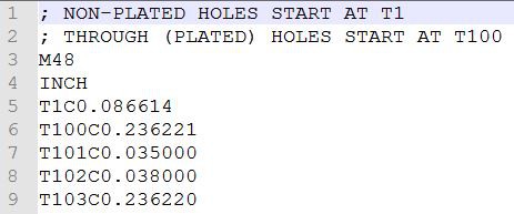
The first lines define the tools to use and their type.
line 6 specifies tool T100, a circle of diameter 0.236221 inches. That's a big drill, probably the plugs. Why do we have T100 and T103? They differ by an insignificant amount. The manufacturer will probably use the same drill for these.
Of interest are drills T101 and T102. T1 is not through plated, so those must be the mounting holes on the corners.
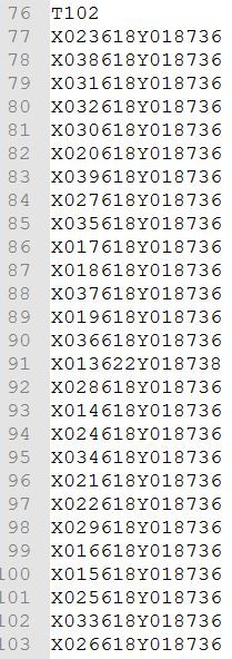
Further down the file, looking at the holes drilled with T102, notice that the Y coordinates at the end do not change, so this must be the header at the top.
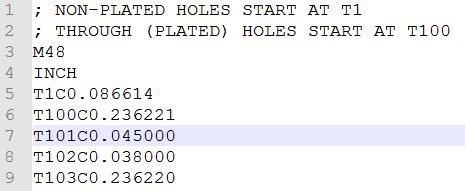
T101 must be the TVS diode legs then... Let's change Tool 101 to a bigger number, let's say 0.045"
Here is a rendering of the original plugboard:
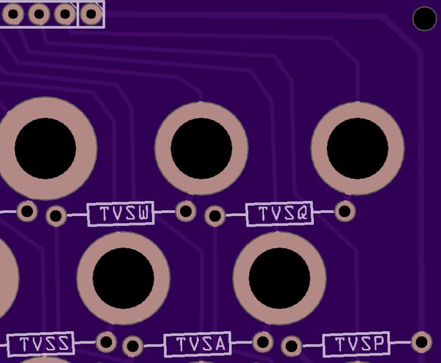
Here is the new plugboard. The size of the copper ring around the plug has been reduced from 2mm to 1.5 in fritzing. But look at the size of the holes on the TVS diodes.
This is an early experiment. Next, let's measure the actual diode legs and select the final drill size.
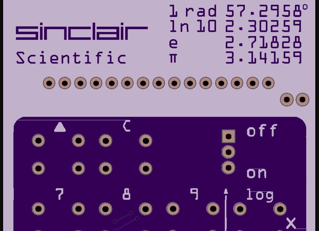
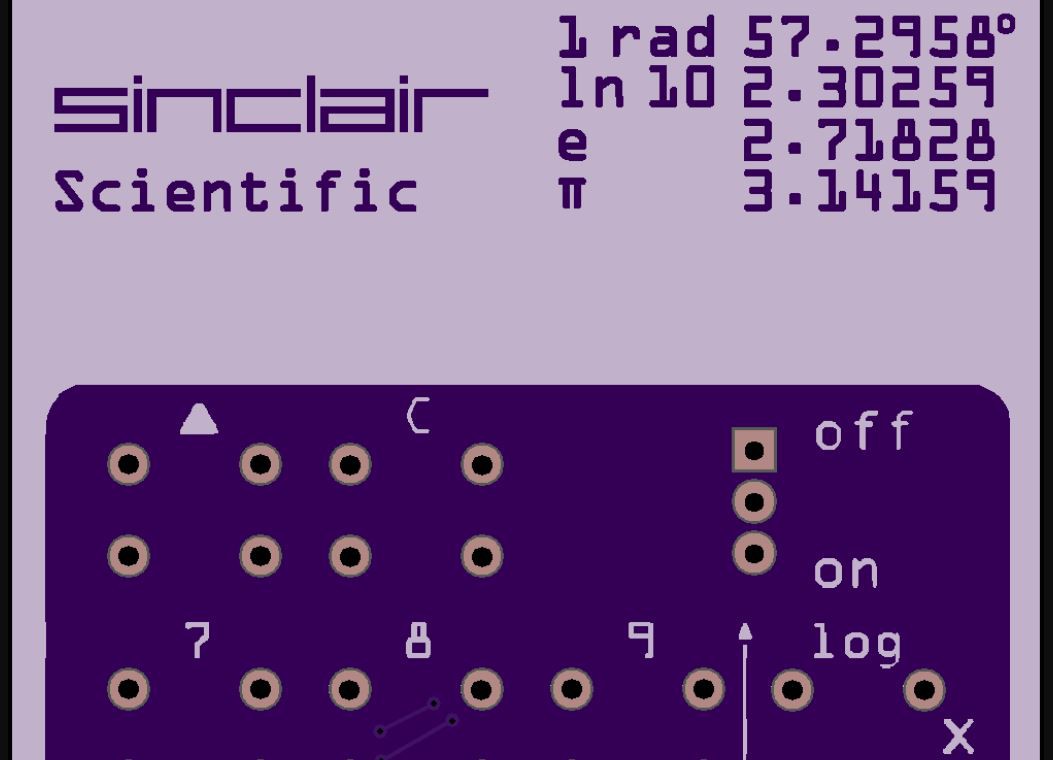
This is the second time ever we have had to go into the Gerber files to manually change something. The first one was to correct some lines that were appearing on the production silkscreen on Sinclair boards. The fix was to increase the diameter of the tool used to paint the silkscreen layer.
The lines at the top of the C letter, log and X were rendered in the production PCB.
The fix was to go in the silkscreen file and slightly increase the tool size so adjacent passes overlap and the line is gone...
Post under #GerberHacks
-
Arduinos and Keyboards Soldered.
06/07/2019 at 11:03 • 0 commentsThe Arduinos and keyboards have been soldered. The Arduino Mega and the 16 Segment Displays have been installed on a socket. The Z30 is all soldered except for the displays, this board will be used to test the displays on-hand and then a set will be soldered.
![]()
![]()
One decimal point is upside down, its ok, its not soldered...
![]()
![]()
![]()
-
The Boards Have Arrived!
06/05/2019 at 10:39 • 1 commentThe boards have arrived from JLCPCB and they are gorgeous. They have this matte black soldermask that conceals traces, (not like there is a lot to conceal on the top layer anyways).
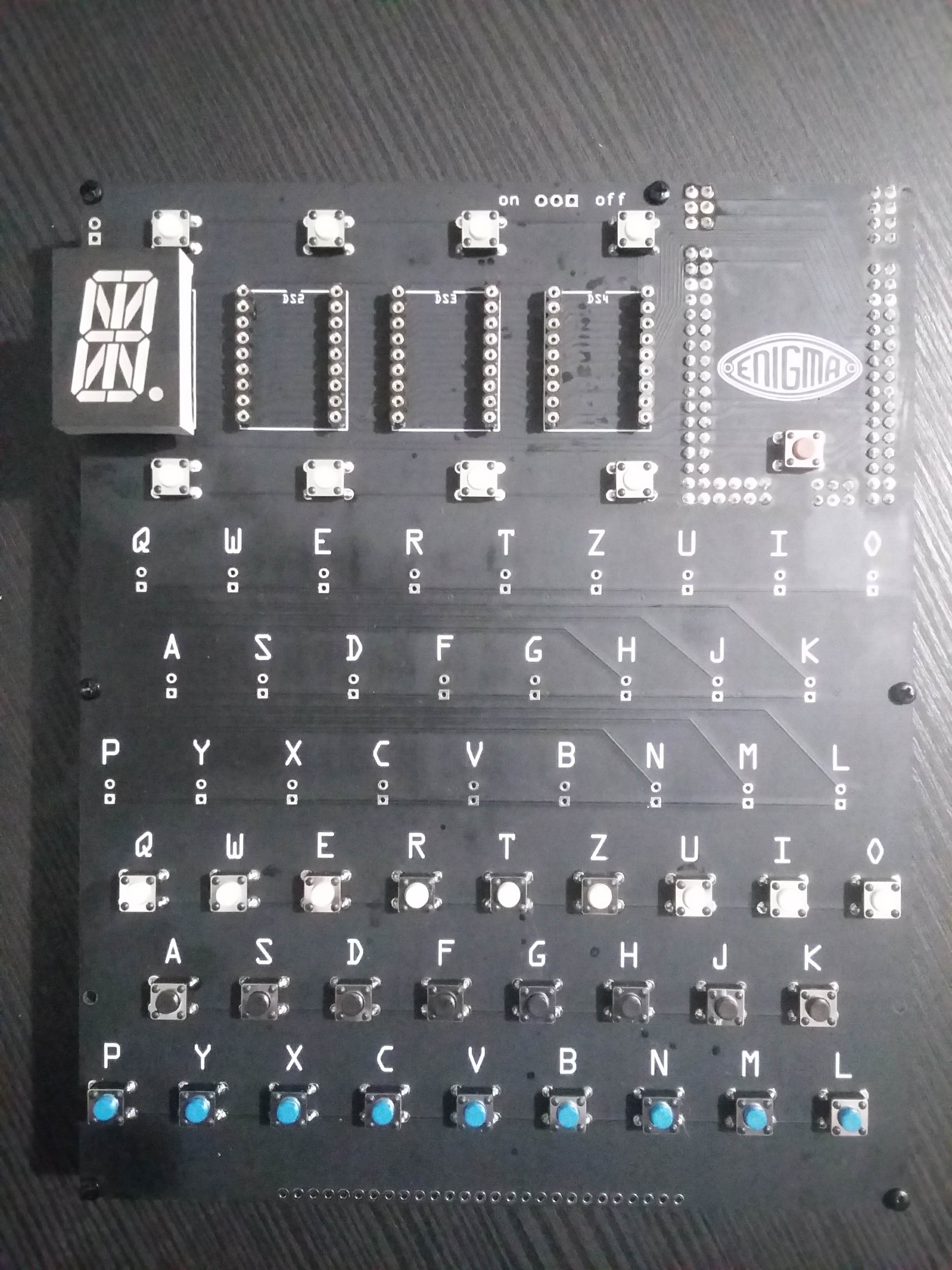
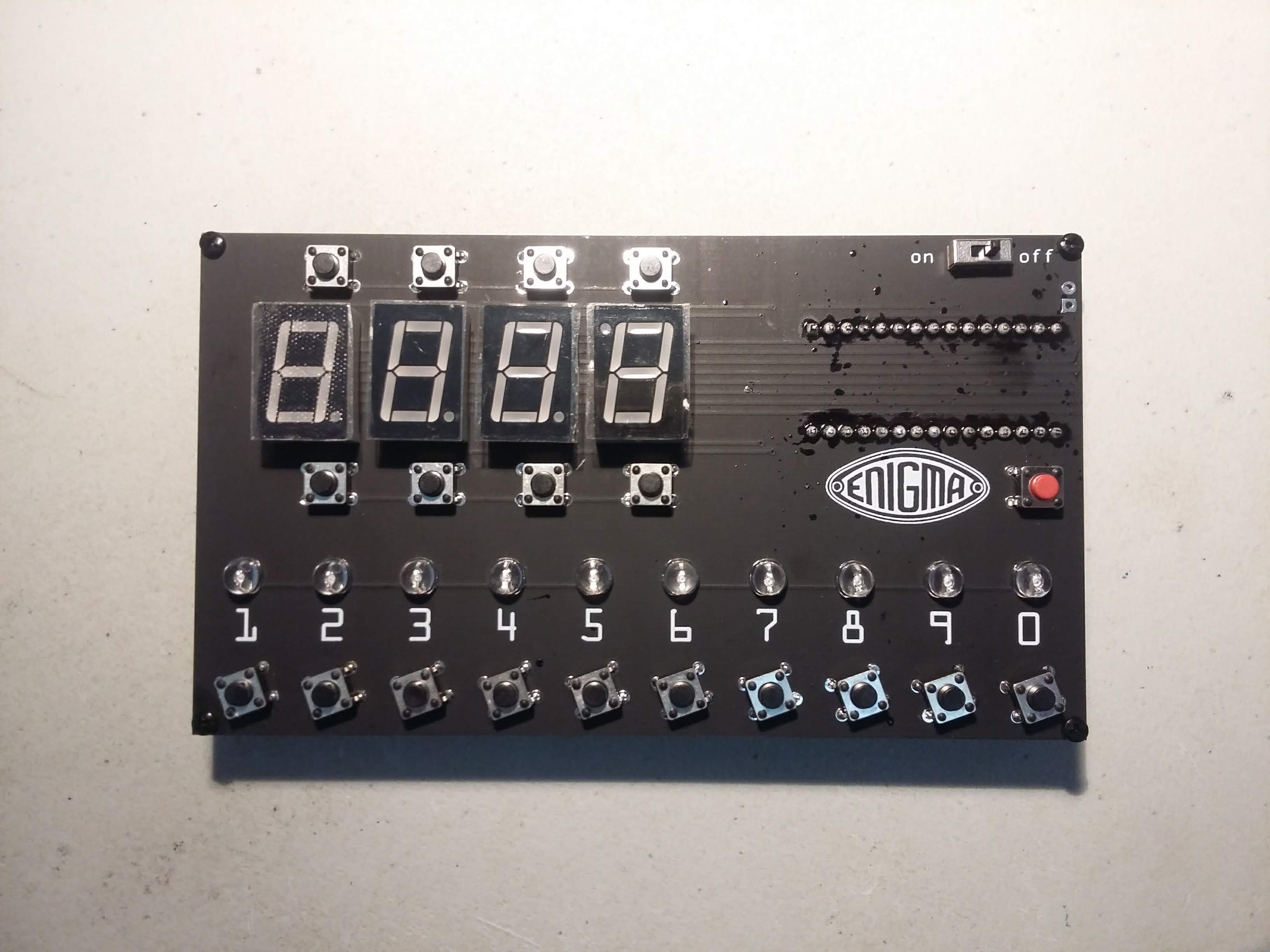
Pictured are the Mega Enigma with plugboard and the Nano Enigma Z30, an Arduino Nano to Uno Shield Adapter is included for scale.
![]()
Here is a picture of the bottom of the board showing the traces going to the plugboard connector. This matte soldermask looks good, but it is a dirt and grease magnet, let's see how well it cleans after soldering all the components on the board. We will be using solder with water soluble flux
![]()
-
PCB Ordered, gets here soon...
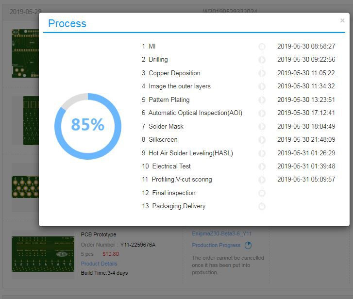
05/31/2019 at 10:40 • 0 commentsThe 16 segment displays were the last components to arrive. Since the pinout matched, the PCB was released for production.
It looks like the PCBs will get here on Monday...
A future repetitive task involves one of this, an Arduino Nano, a custom PCB and a laser cut base. Can you guess what is it going to be?
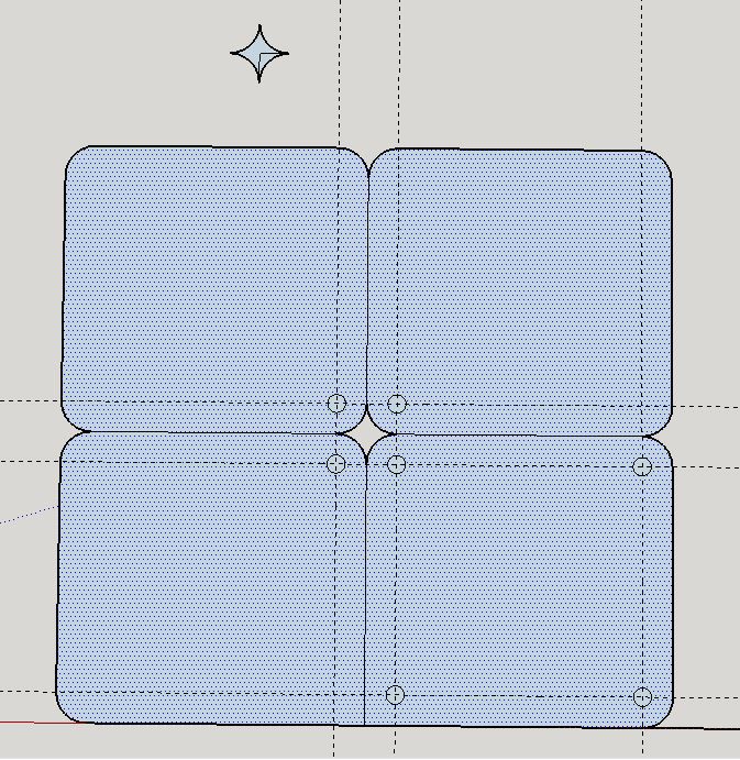
This looks like a way to arrange laser cut panels to resuce cost
-
Reading the plugboard with a state machine
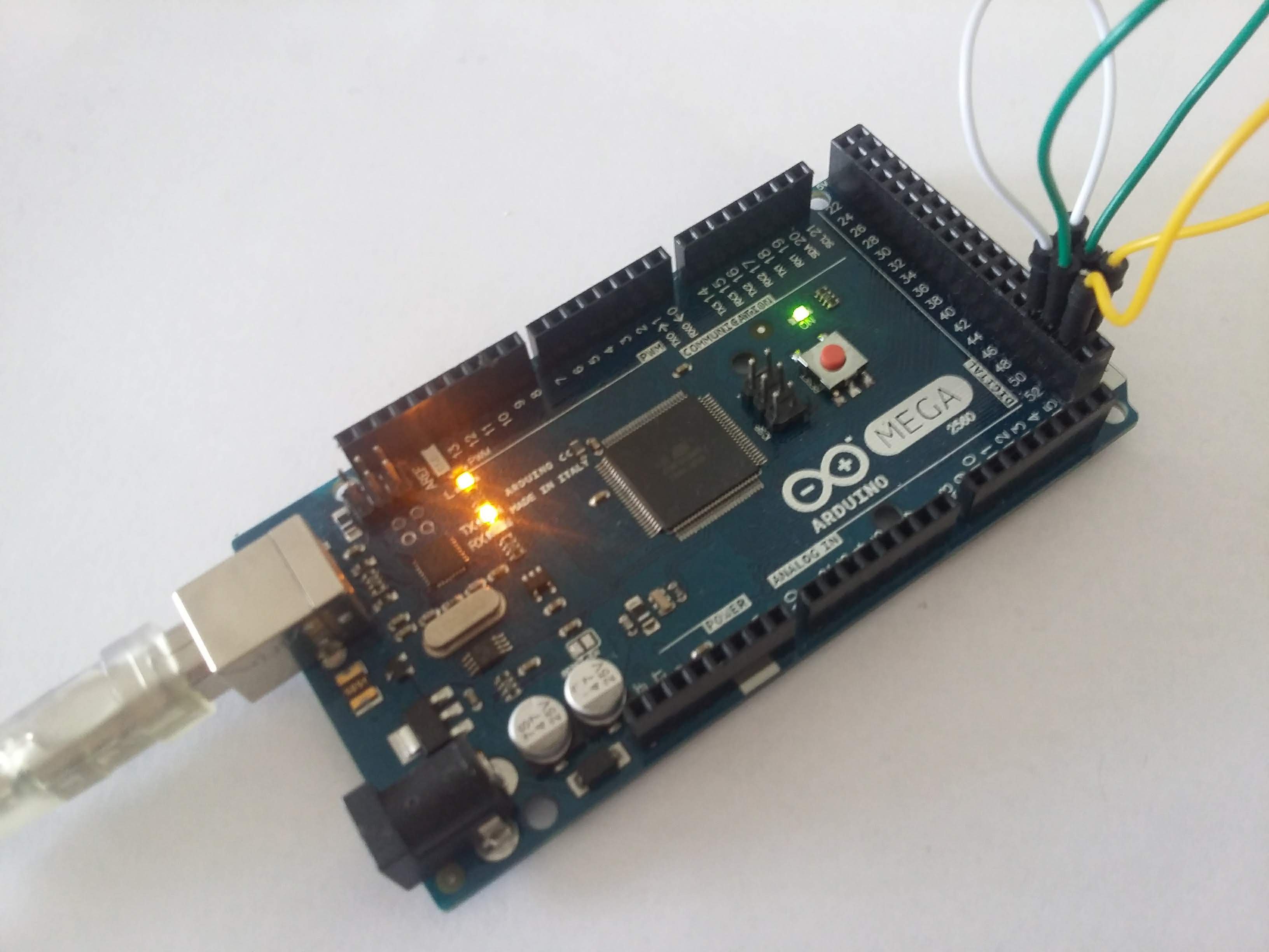
05/27/2019 at 17:30 • 0 commentsUsing a genuine Arduino MEGA to test the plugboard logic:
![]()
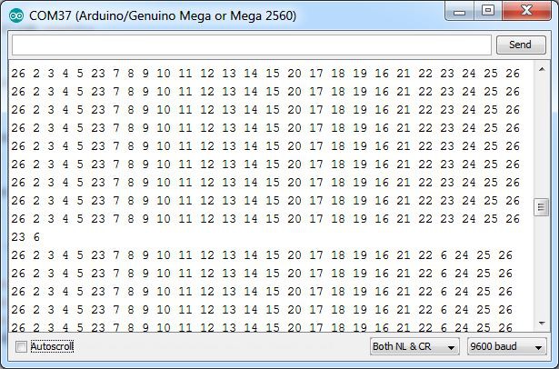
All the plugboard pins are set to input with the pullup resistor activated. One at a time, each plug is set to output and low. The other plugs are read one at a time, a 0 is returned if the other end of the plug is installed, otherwise a 1 is returned.
The code is implemented as a state machine and only one I/O operation is done each time it is called. This routine needs to be called once or twice in between changing the display from one digit to the next.
Thie state machine takes 24us to run.
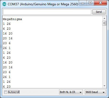
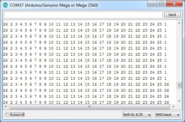
Here a list of the installed plugs is shown:
The code stores any plugs detected in an array. The scanning process is shown below.
Notice that column 23 changes to 6 as the plug is discovered. Column 6 was already changed to 23 as one side of the plug was discovered.
Detecting when a plug is removed is equally important. and a different logic is needed. If all the plugs are read and neither returns 0, reset the plugboard entry to itself. Notice the last row changes from 1 to 26 once the A-Z plug is removed;
https://gitlab.com/arduinoenigma/megaenigma/blob/master/DisplayAndKeys.ino
-
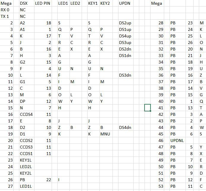
LED and Keyboard Pin Assignment Completed
05/25/2019 at 16:51 • 0 commentsThe pin assignments have been traced and double checked. Each LED and switch on this board can be uniquely addressed with two microcontroller pins.
This simulator uses a fairly conservative multiplexing design to light up the LED and read the keys. There are a lot of different devices on each pin, but that is solved in software by controlling each device at a different frequency. The 16 segment displays need to be driven more frequently to eliminate flicker. The keyboard can be read one key at a time when switching from one sixteen digit display to another. The lampfield can be treated like another sixteen segment displays and if needed, multiple lamps can be lit simultaneously.
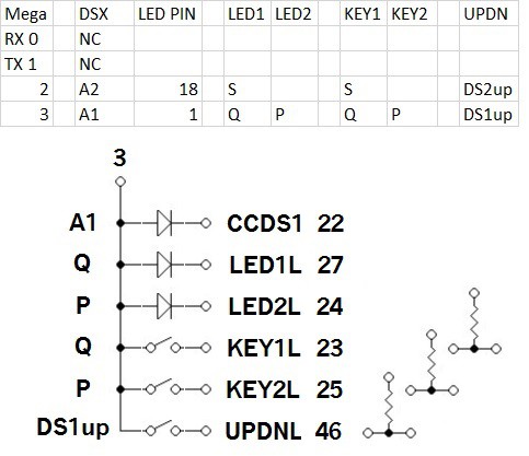
Here is a detailed schematic for one row, pin 3 is selected because it has 6 devices. Other lines may not have anything connected on LED2L, KEY2L or UPDNL (schematic made with the Klunky Schematic Editor https://www.qsl.net/wd9eyb/klunky/home.html)
![]()
Pin 3 controls one side of:
1) Segment A1
2) Lampboard letter Q
3) Lampboard letter P
4) Keyboard letter Q
5) Keyboard letter P
6) Up Key for Digit 1
Here is the algorithm to illuminate and read all of the devices (although not at the same frequency)
1) put the correct bit pattern on A.. H segments for digit 1 (active high). In order to control the brightness difference between letters with a lot of segments and letters with few segments, this task can be subdivided in two by putting the bit pattern for 8 segments first, then putting the pattern for the other 8 segments.
2) make the CCDS1 line active low to illuminate the first 16 segment digit. Make CCDS2..CCDS4 high or inputs to prevent anything from showing in digits 2..4
3) make the LED1L and LED2L lines high or inputs to prevent anything from showing in the lamp field.
5) Wait 400uS or execute an Enigma encoding task that takes less than that time to execute.
6) Make all the segments 1 in preparation to read the keyboard
7) Make 1 segment low, start with A1, on next iteration, select A2...
8) Read KEY1L, if 0, Q is pressed
9) Read KEY2L, if 0, P is pressed
10) Read UPDNL, if 0, DS1up is pressed
11) repeat step 1, but activate CCDS2 to illuminate the second 16 segment digit. When all four 16 segment digits have been illuminated, repeat step 1 again but activate KEY1L, then repeat one more time with KEY2L
Here are the tasks one at a time:
1) letter pattern (active high)
2) CCDS1 (active low) and wait 400us
3) Read one set of keys (set one segment to low and read KEYxL for low)
4) letter pattern
5) CCDS2
6) Read next set of keys
7) letter pattern
8) CCDS3
9) Read next set of keys
10) letter pattern
11) CCDS4
12) Read next set of keys
13) lampfield pattern
14) LED1L
15) Read next set of keys
16) lampfield pattern
17) LED2L
18) Read next set of keys
It looks like a state machine will take care of the multiplexing.
(AT) Mega Enigma, a 2560 Pro Mini Enigma Simulator
A minimalist 139x171x50mm Enigma Machine Simulator with working plugboard using an ATmega 2560 Pro Mini and a custom PCB.
 Arduino Enigma

