agp.cooper
-
Laser Cut Acrylic Design
05/19/2019 at 12:50 • 3 commentsLaser Cut Acrylic Design
Although acrylic looks fantastic the problem is that it "shatters". Not immediately but slowly. So you cannot "stress" the material. At least that was my experience with acrylic so far.
But polycarbonate (i.e. Lexan) is much better. So if possible I should use Lexan.
Perhaps I am paranoid? Anyway, to reduce the stress ramp up on the acrylic, I will use nylon washers and promise not to over tighten the bolts.
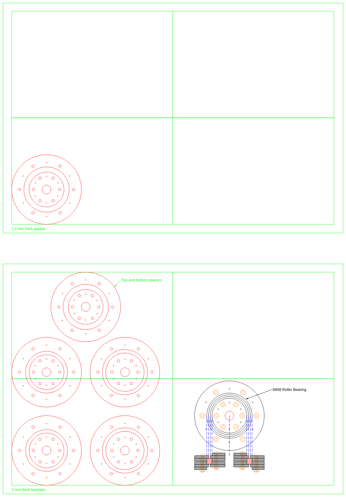
I am looking at a design for 3 mm acrylic, but I could find a suitable thickness of "soft' material to make a gasket from the laser cutting service provider's material list. So I will add the option to use two 2 mm thick acrylic rather than one 3mm thick acrylic.
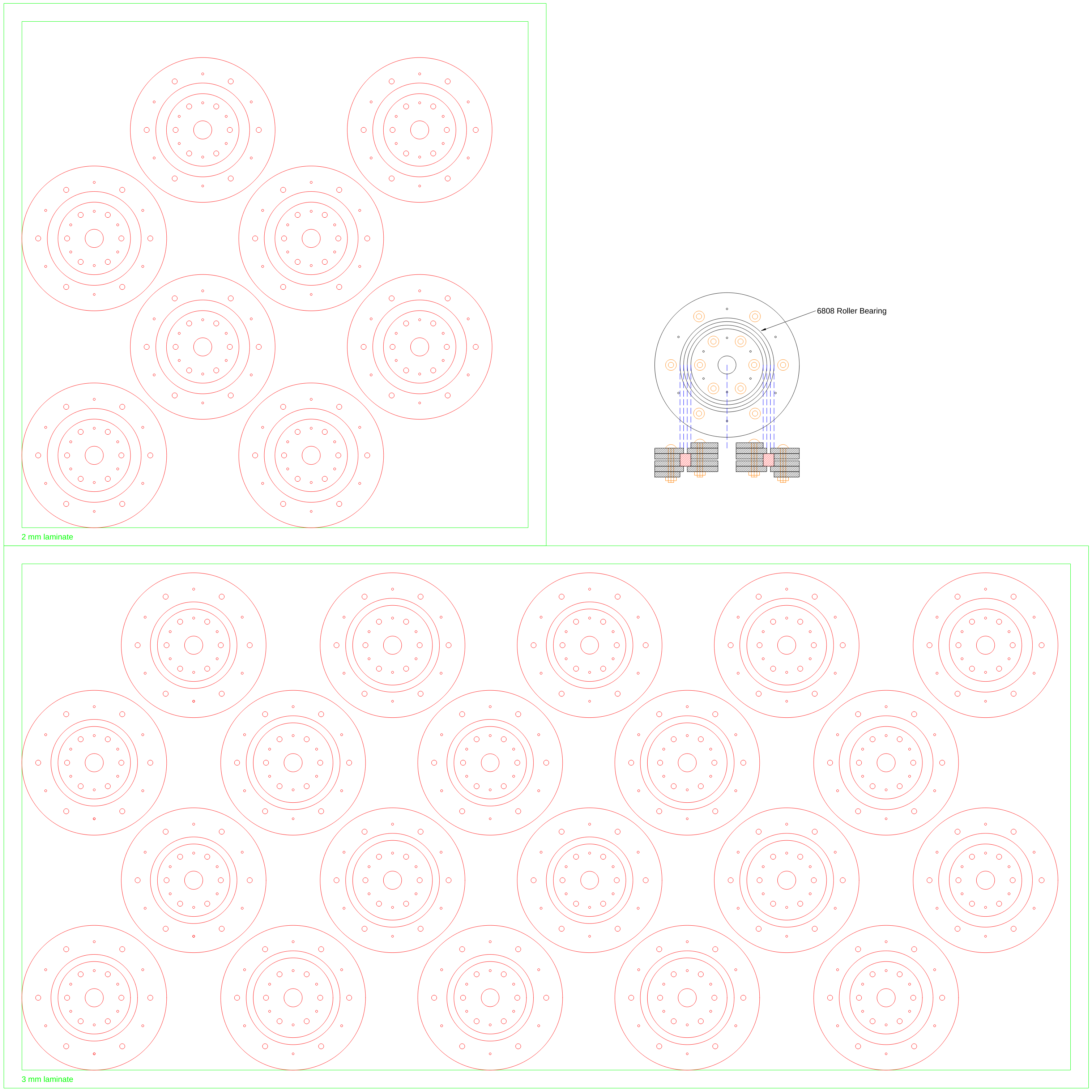
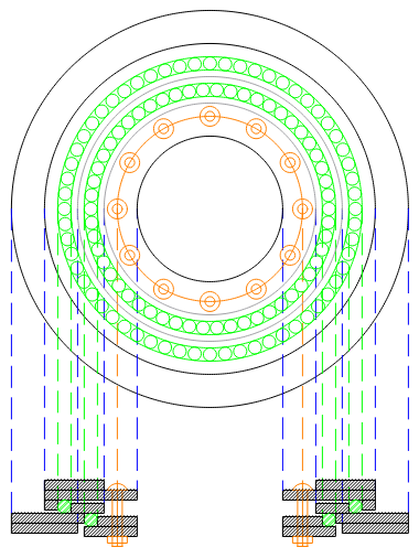
Here is the design:
![]()
Why so many "rings", yes it is for four slew rings. The rings may look the same but there are three size sets.
Quote Received
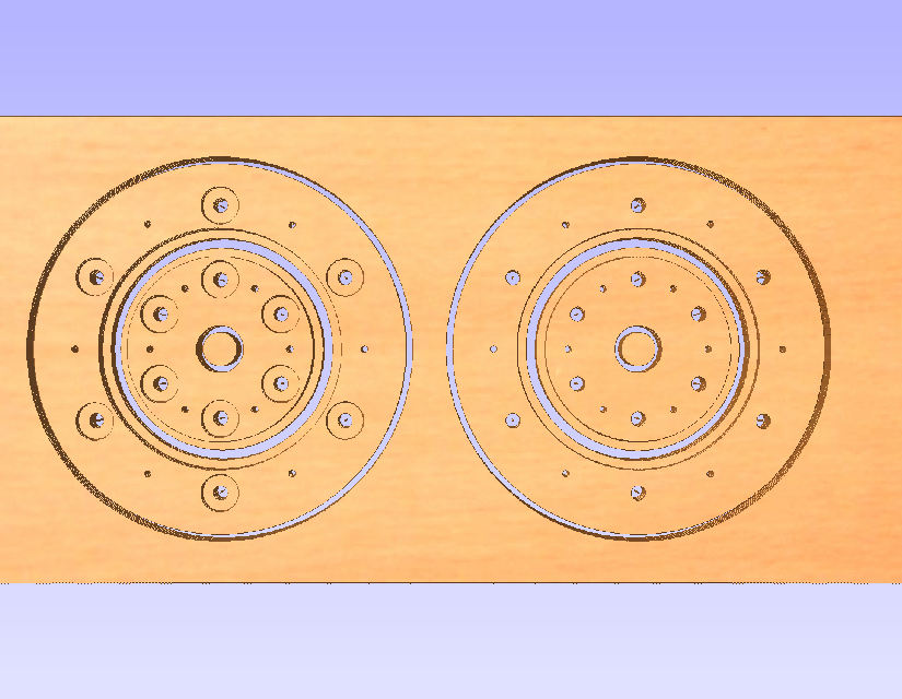
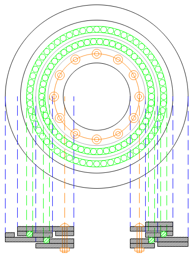
At approximately $160 I don't think so. So I bought a 400 mm x 400 mm x 8 mm sheet of poly-carbonate for $36 and I will redesign a single slew ring using four pieces:
![]()
Only the bottom left corner is CNC milled. The alignment holes will be used to relocate the disk when it need to be turned over.
Time for CAM (Cut2D). Cut2D is a great program. I bought the version 1.1 so it is unlimited!
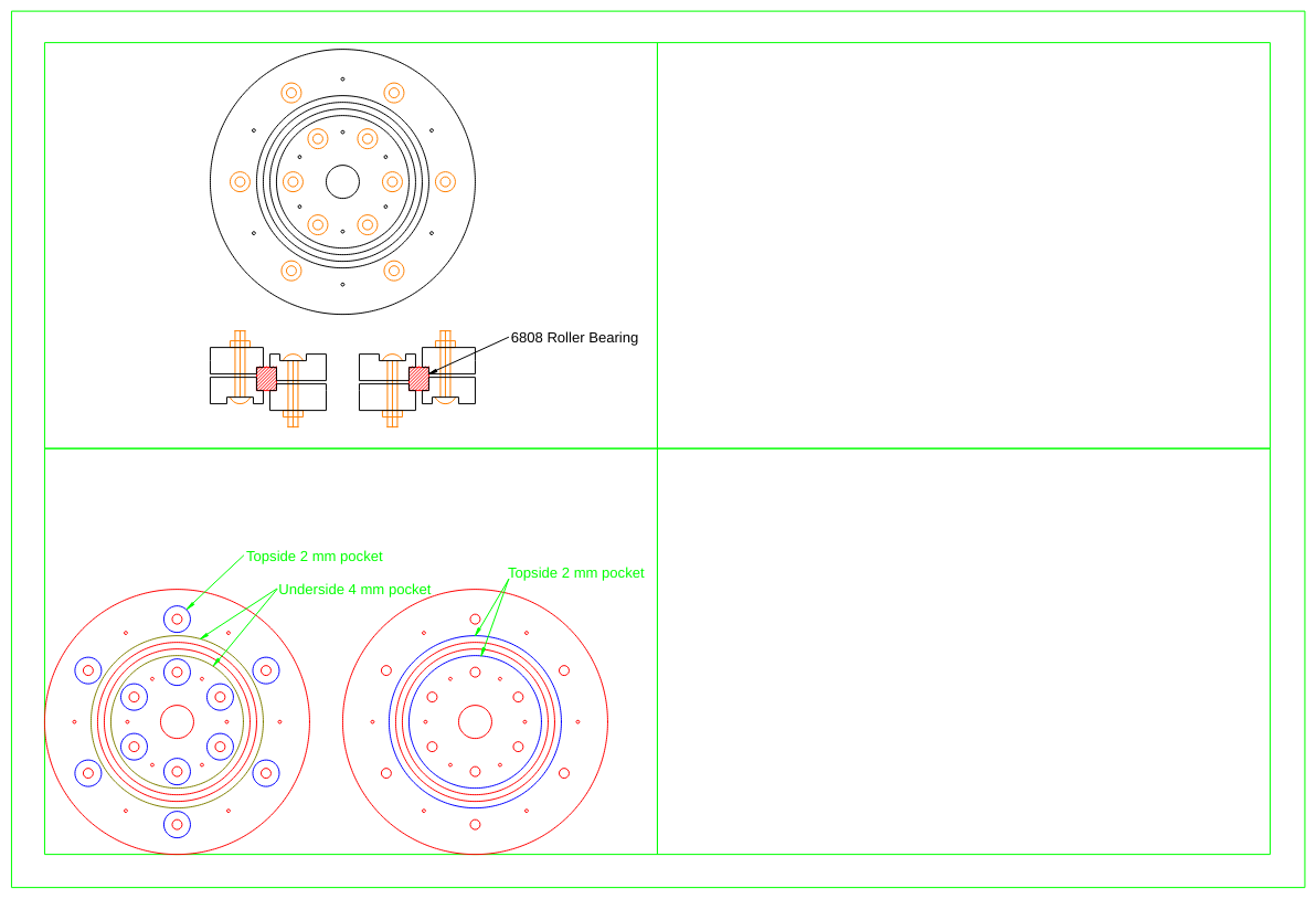
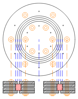
Here is the CAM image:
![]()
Note the bolt pockets are actually on the underside of the first disk.
While I am waiting I have been playing with the design. I can add a 120 tooth 2mm GT2 profile to the outer ring. It is about the same size.
Yeah I wrote another pulley program but for the 2mm GT2 profile. I will bin the T5 pulleys and belts (I am not going to use them now, since I have order a set of 2mm GT2 belts and pulleys).
CNC Feed Rates etc.
This is tough! I will be using a 1.3 mm two flute carbide end mill. I am thinking of 600 mm/min (fast) but a cut depth of 0.25 mm. Apparently it needs to be fast not to overheat (melt) the poly-carbonate.
A 2 flute carbide end mill should be fine running the spindle at full speed (12k). I will need to keep the poly-carbonate cool (water spray?) and the bit clear (compressed air).
If it works okay, I will speed things up by increasing the cut depth to 0.5 mm.
---
Installed PlanetCNC (i.e. USBCNC). There is a Linux version. Some focus problems (annoying) and some protection problems to work out. The first simulation suggested more than 7 hours! Far too long, so I increased to plunge rate from 50 mm/min to 150 mm/min and it is now down to 3 hours. I can work with that. Still waiting for my cutters.
---
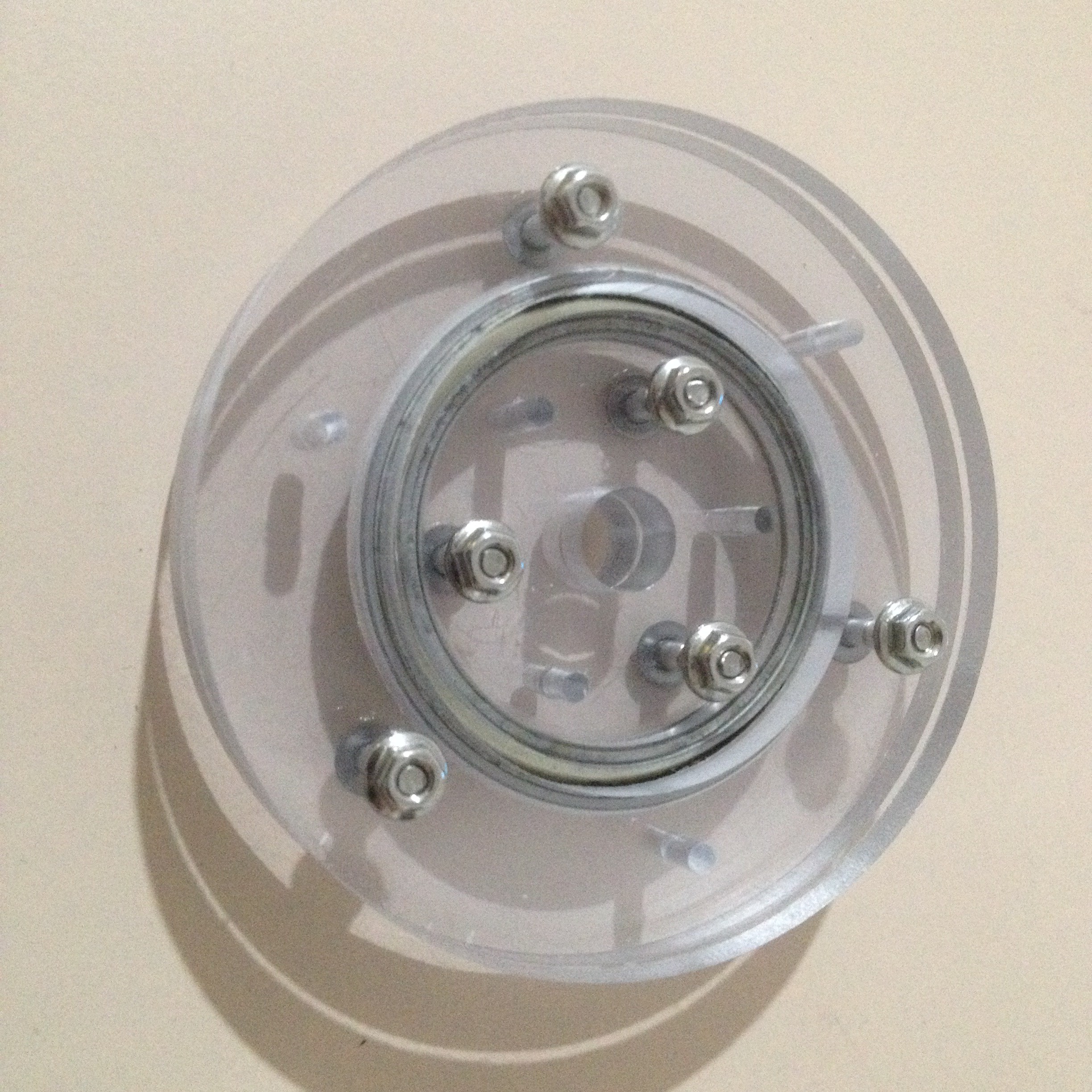
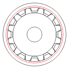
I have cut the design. Went okay, Window froze half way, and I had to slow down the spindle to stop the cuttings melting together to make a "string". Not good, it wraps around and bonds to the end-drill. I will have to measure the bearing next time as the inside disks are too loose and the outside rings (holes) are too tight. Perhaps 0.2 mm off. Otherwise the bearing is quite good, unable to detect movement by hand:
![]()
I will need to add a spacer between ring to stop flexing.
So I will increase the feed speed (1200 mm/min?) and the acceleration (50 mm/sec/sec?).
I will also need to compensate for profiling beyond "climb" and "conventional", I think I may call my 2 mm end-mill a 1.9 mm end-mill.
Finally, I need to break the project up into little jobs and drill some "index" holes when I have to reset the work origin.
AlanX
-
What I have Learned
05/19/2019 at 01:00 • 0 commentsWhat I have Learned
Okay, I have not built anything yet but here are some observations:
- Although the path is longer it was good to start with what can be cut with a laser cutter (2D) and then regroup the layers for a CNC milling (2.5D). Keeping both options open gives flexibility.
- I would question building an open races when similar dimension roller bearings are available of a very reasonable price?
- It it probably easier to match the bearing thickness to the sheet thickness than not.
- In my designs I have both dowel (i.e. 1.25 mm diameter nails) alignment and bolt alignment. If the layers are glued, then the dowels can be removed).
- Permanent dowels and split dowels are an option where disassemble is not required.
- For wood (MDF) PVA glue is fine, for acrylic #16 acrylic glue is fine (but use safety precautions as it contains very nasty chemicals (methyl chloride)).
- Full thread bolts are available in lengths up to about 80 mm and studs even longer. I am no longer relying on the bolts for alignment.
- Not hard to design steps to use allow the use of shorter bolts or the use a mix of bolts, glued lamination and permanent dowels.
- There is a trade off between thicker sheets and manufacturing. It is not easy to cut thick sheets (i.e. greater than 12 mm). It may be better to laminate (glue) sheets (i.e. 6 mm) for thicker sheets.
- The size of my CNC machine limit the size of my project.
- Although expensive, commercial laser cutting services can cut pieces beyond the size limits of my CNC machine.
Some slew ring design concepts using roller bearings.
Double open race #1:
![]()
Double open race #2:
![]()
Single roller bearing #1:
![]()
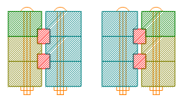
A double roller bearing (with gaskets) #4
![]()
If the roller bearing thickness matches the sheet thickness then a single roller bearing design #5:
![]()
An finally a 2.5D CNC double version of #5:
![]()
Looking at #6 I wish I could just weld a flange with holes on the inside and outside of the roller bearing.
Anyway, I think I should build a couple to see what they are like in practice.
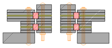
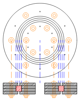
Here is the 2.5D CNC layout of design #1 but with gaskets:
![]()
AlanX
-
SCARA Designs
05/16/2019 at 14:04 • 0 commentsSCARA Designs
Here are a couple of SCARA concepts:
![]()
And:
![]()
And something that looks almost there:
![]()
There looks like three sheets for this design, one 3mm and one 12mm, and a 1mm gasket.
Beam Stiffness
The stiffness of the arms can be increased by using a stiffer material or increasing the thickness (or both). Alternately I can add stiffening elements (flanges) to the arms.
I have decided to add flanges to the arms to increase the arm stiffness. Think of "U-channel", for what I am planning.
Another Day of Design Work
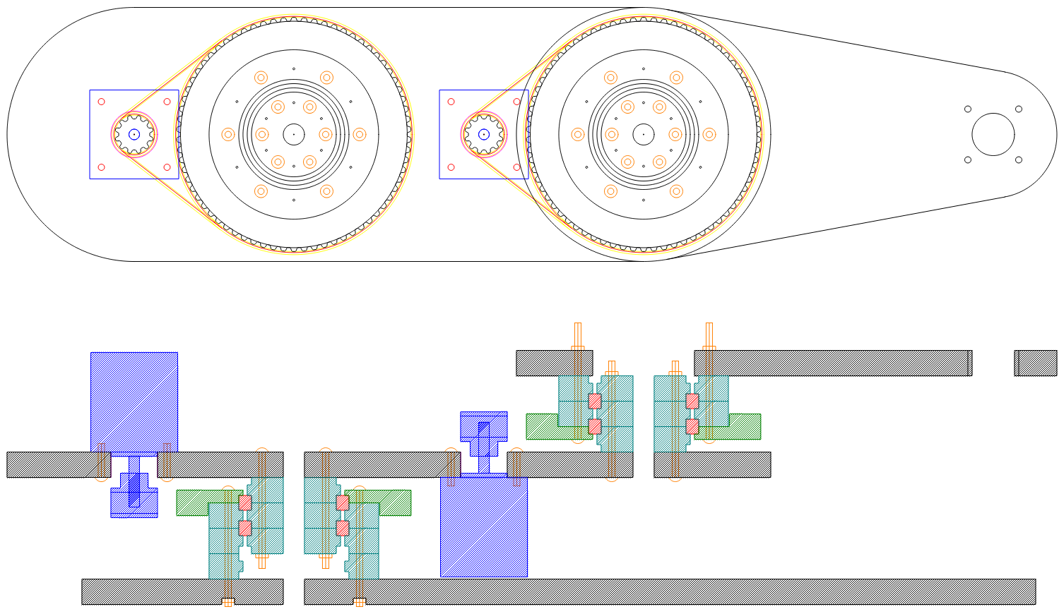
After another day of design:
![]()
All cut from 12 mm thick (MDF, plywood or Lexan). Plus a limited number of design pieces (three plus the base board and two arms). The bolt length are based on what I have available.
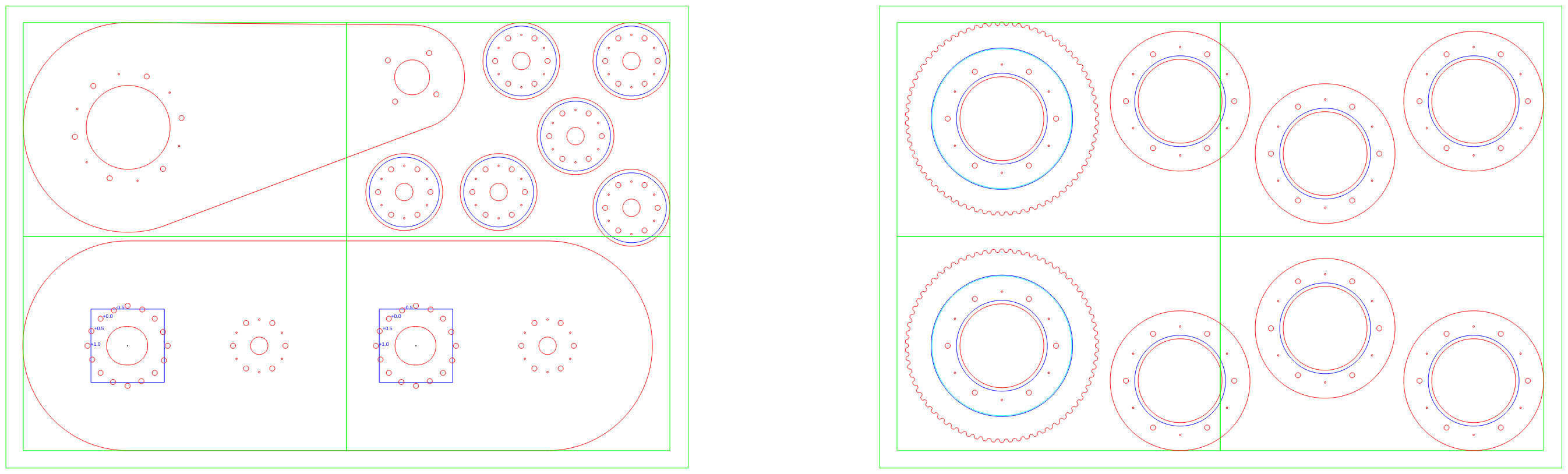
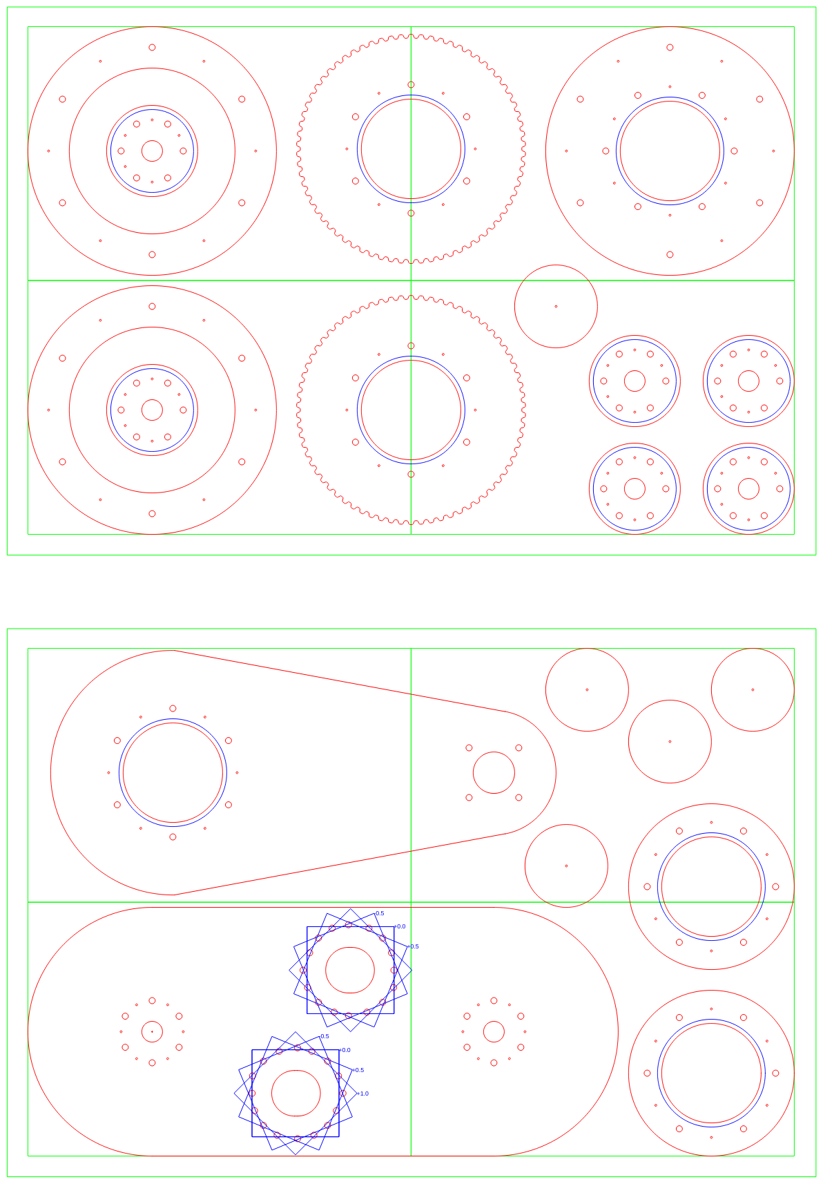
I have made a layout (except for the base board):
![]()
These layouts (two) are for my CNC machine. The extra holes around the stepper motor mounts, allow for -0.5mm, 0mm, 0.5mm and 1.0mm relative adjustments of the stepper motor position. This allows adjustment of the belt tension.
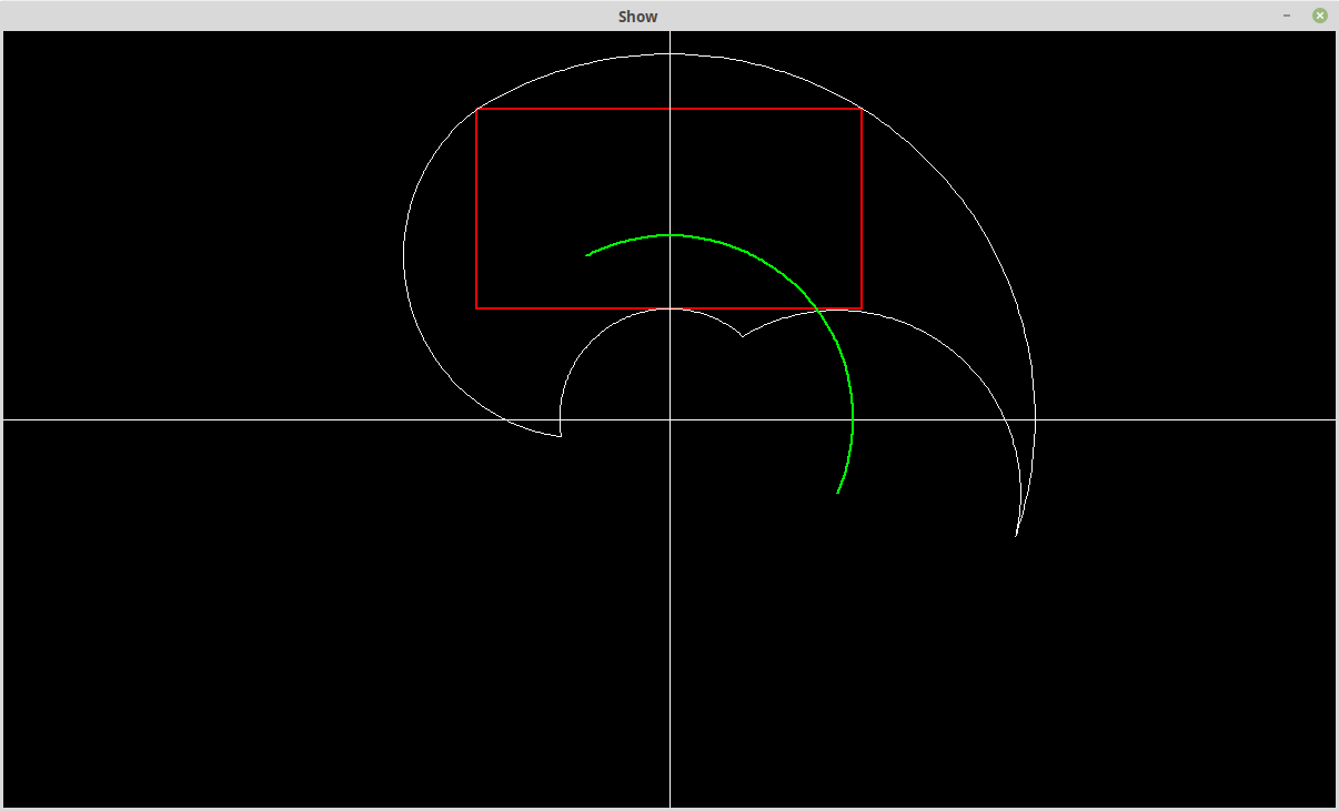
I have also looked at the 2 to 1 SCARA working area:
![]()
The bottom of the red box is does not clear the second stepper motor and need to be lifted at least 10 mm. The effective working area is 330 mm wide by 165 mm high, and both arms are 165 mm long.
Another Day of Design Work
The design is progressing. Other than two 3 mm shims (for clearance), the design is all 12 mm thickness. I have laid it out for cutting on my CNC machine. Unfortunately I don't a bit small enough and long enough to cut the pulley. I have ordered a 17mm long 2mm (2 flute) bit from within Australia. And the base board is too big for my CNC machine. I will have to hand cut and drill that.
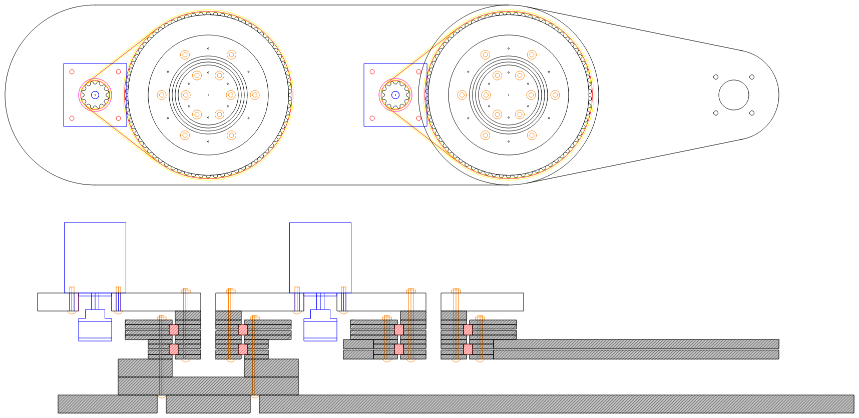
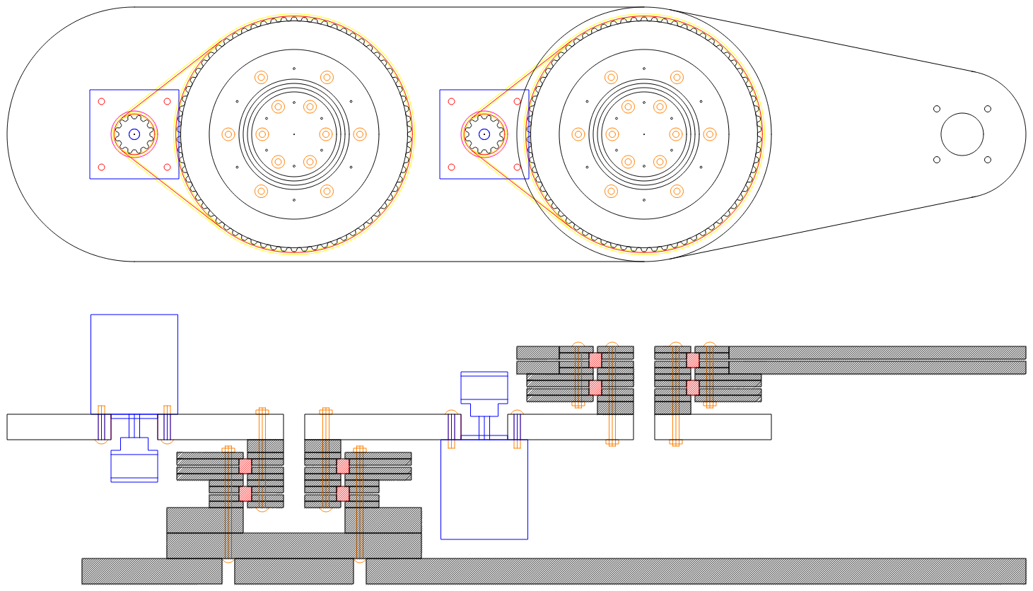
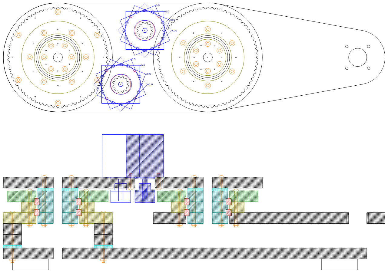
Hers is the plan and section views:
![]()
Note the stepper motor has four rotated locations providing -0.5mm, +0.0mm, +0.5mm and +1.0mm offsets for timing belt adjustment.
I have looked around and I can get the 6808 bearing in a 6mm width (i.e. 6708). This means I can laser cut a design for the slew ring (no need for 2.5D machining). This will be looked at for the next prototype.
I have also sourced some 80mm long M3 bolts so I can add more layers.
Hers is the layout:
![]()
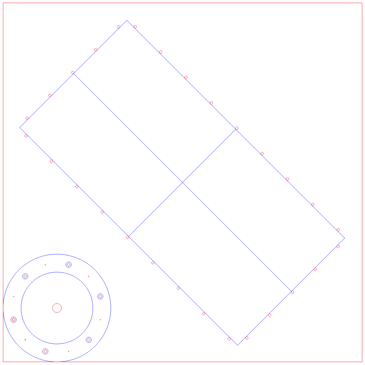
And here is the base board:
![]()
It is a 45 degrees to keep the base board as small as possible.
The next problem to solve is the location of the homing switches.
AlanX
-
Pulley Design
05/16/2019 at 05:50 • 0 commentsT5 Profile
I started with the T5 pulley and belt profile because I need a large tooth to suit CNC machining. But recently I found that the GT2 profile can be drilled with a 1.3 mm diameter bit. Sure the outside perimeter still need to be cut. So I will reconsider the pulley and belt profile later.
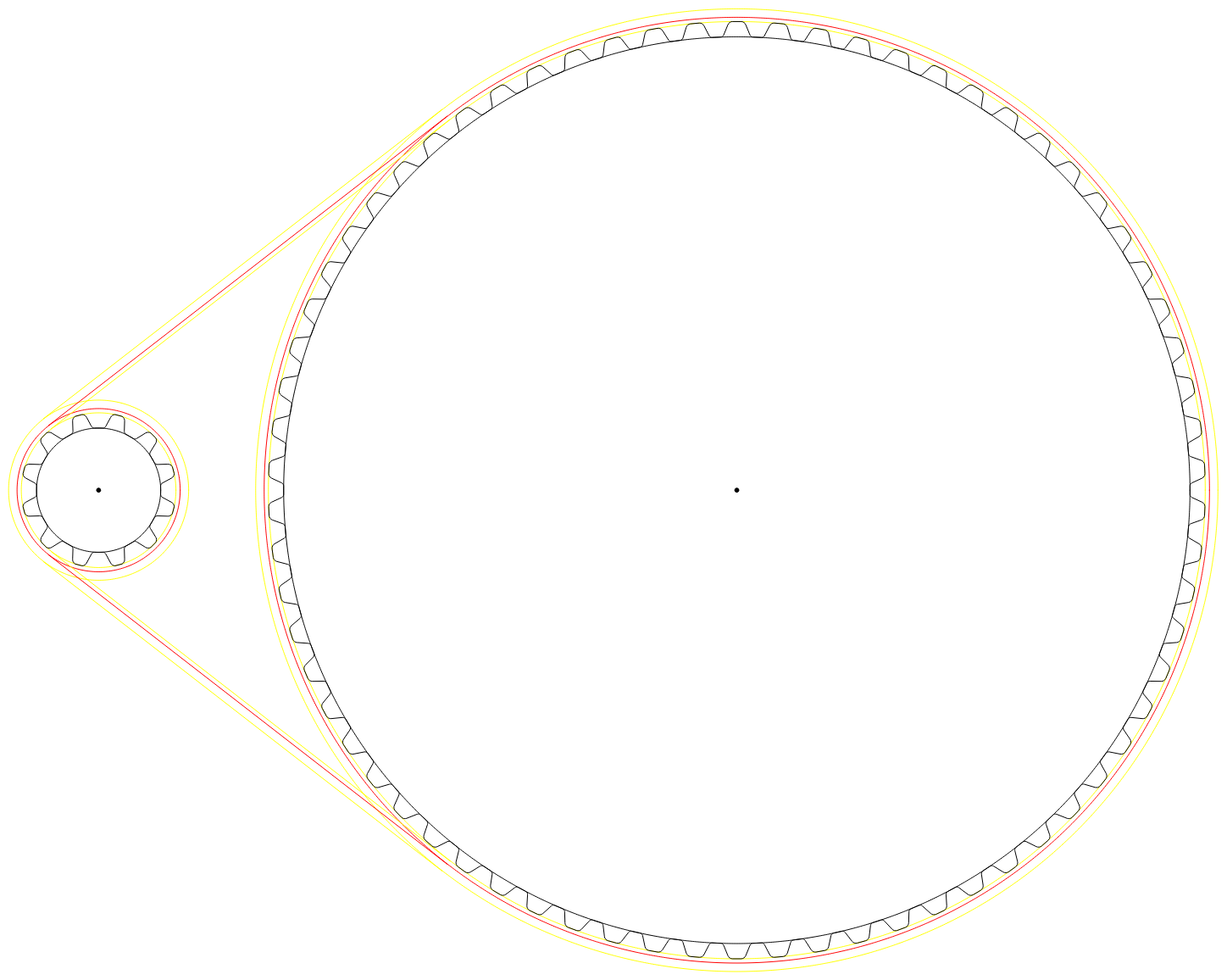
Here is the 12 tooth pulley and belt profile that I coded:
![]()
The belt is wrapped around the pulley (the red circle is the pitch circle).
Note how loose the fit is! This appears to be part of the design feature:
![]()
Other belt profiles (GT2) have lower backlash and should be considered later.
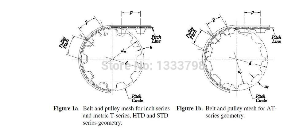
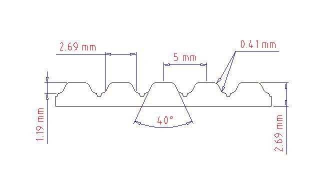
Here is T5 belt profile:
![]()
and the pulley profile:
![]()
And here is the design:
![]()
Here are the calculations:
Cog and Belt Design T5 Pitch 5.000 mm Z1 12 t Z2 60 t Z1 Pitch Diameter 19.249 mm Z2 Pitch Diameter 95.643 mm Pitch Centre (meshed) 57.446 mm Offset 17.868 mm Cog Centres 75.314 mm Belt Length 350.000 mm Belt Teeth 70.0 Z1 Outside Diameter 18.249 Z2 Outside Diameter 94.643 I will upload the spreadsheet to the file area.
AlanX
A 2.5D Slew Ring
I need a slew ring for my SCARA. I don' have a 3D printer so it has to be either laser cut (2D) or 3 axis CNC milled (2.5D).