 alessandro verdiesen
-
1Magnetic connectors
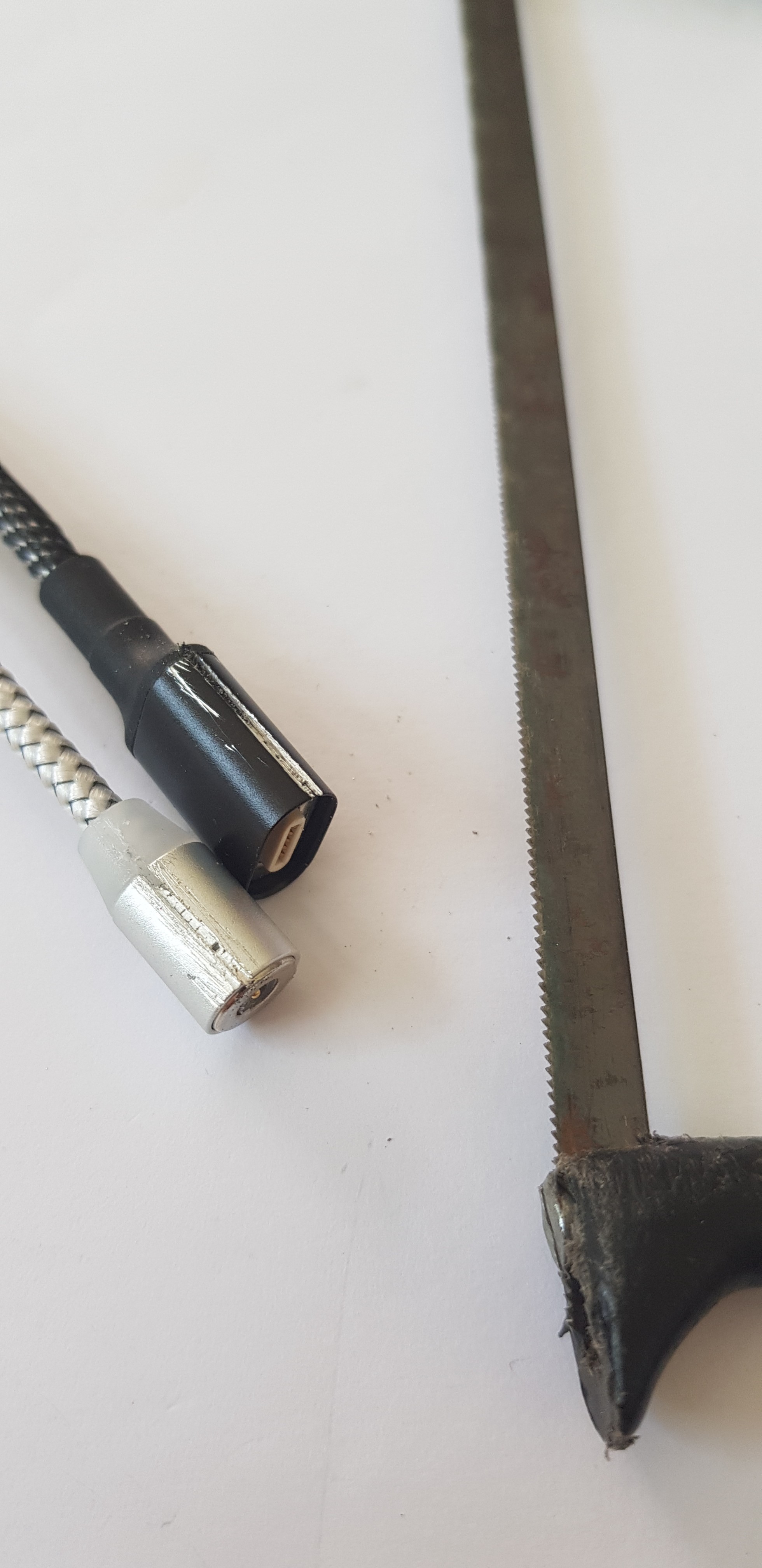
1. Saw open the casing
![]()
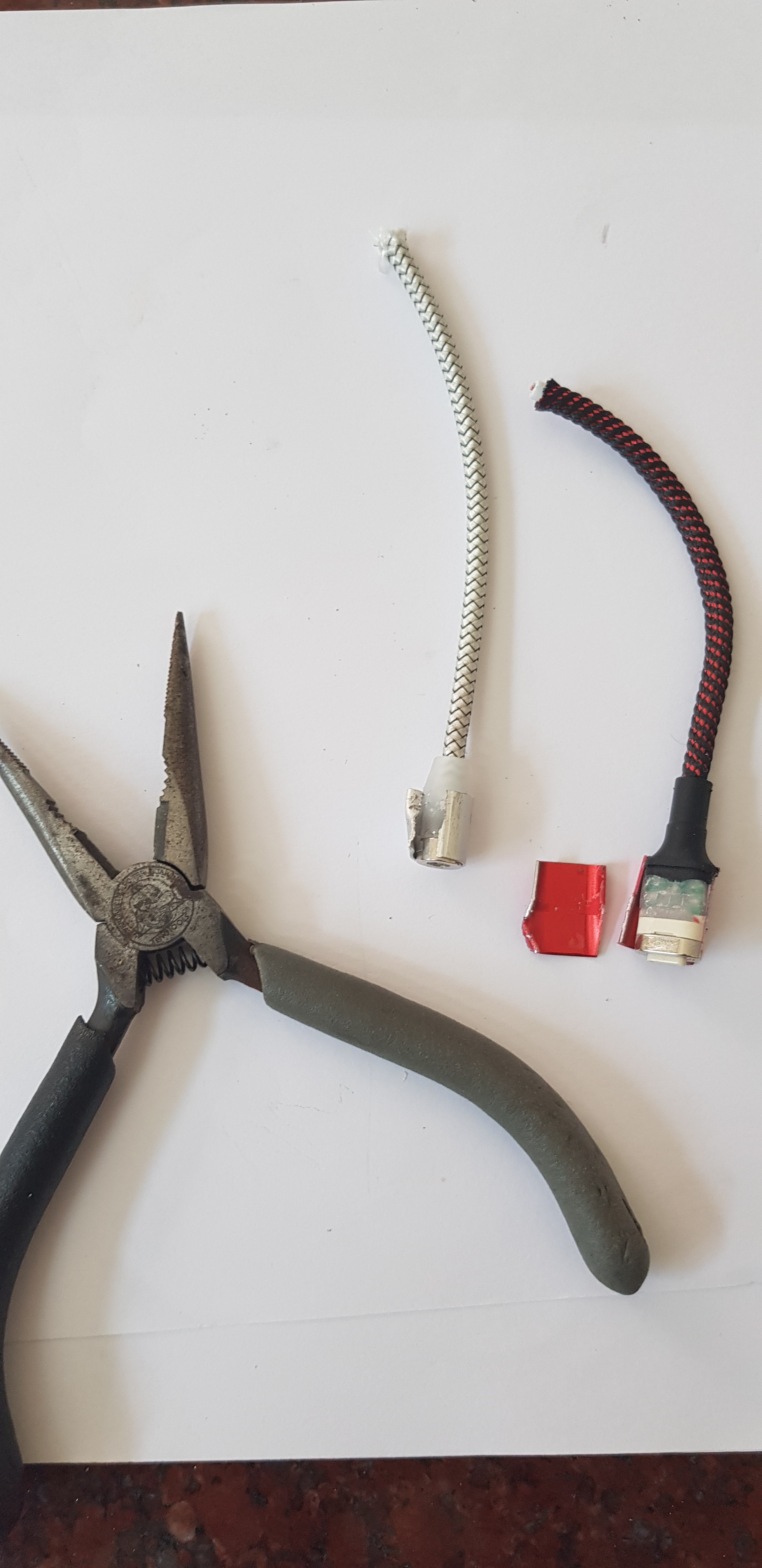
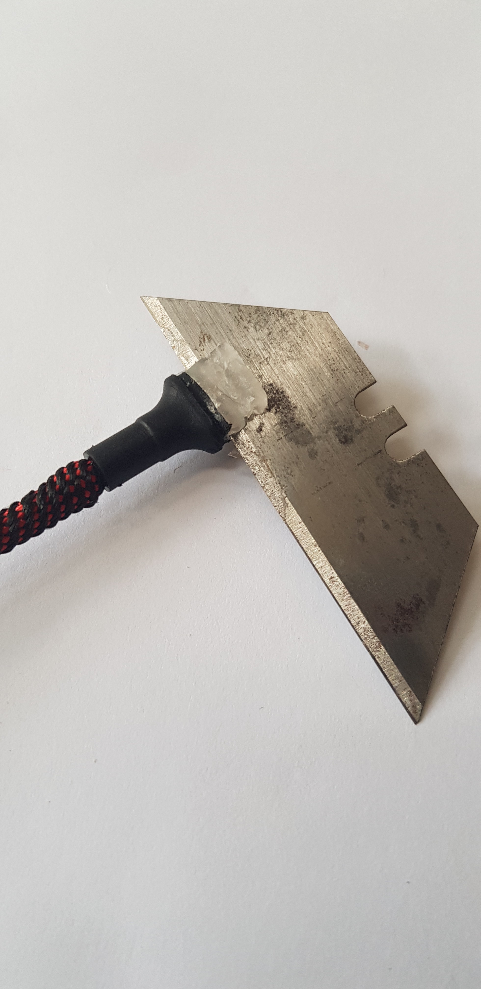
2. Break them open with a pair of pliers
![]()
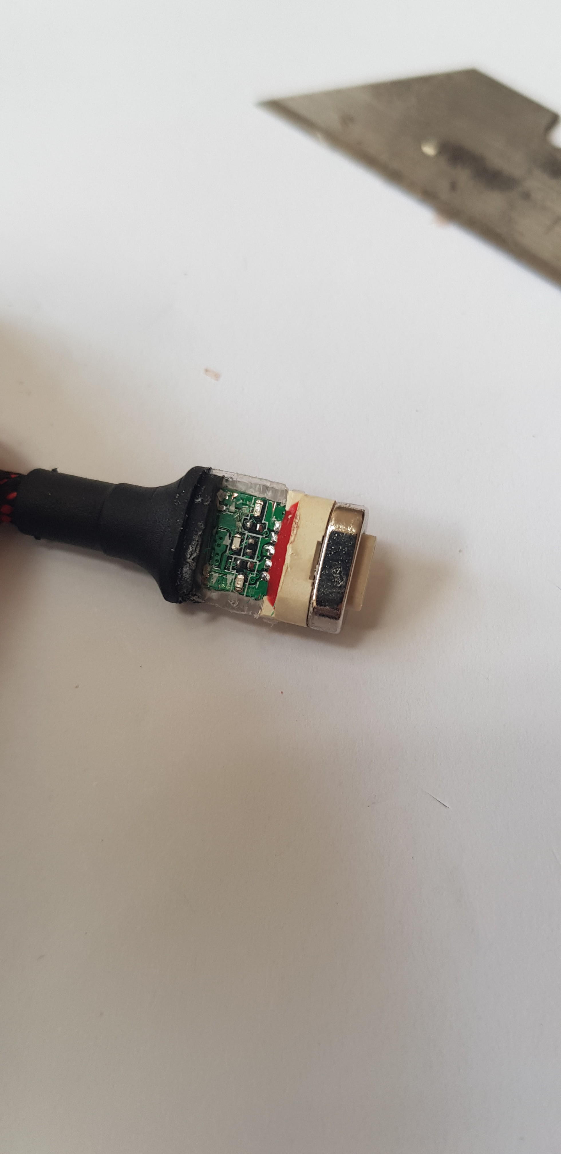
3. Remove the internal LED's in the data connector
![]()
![]()
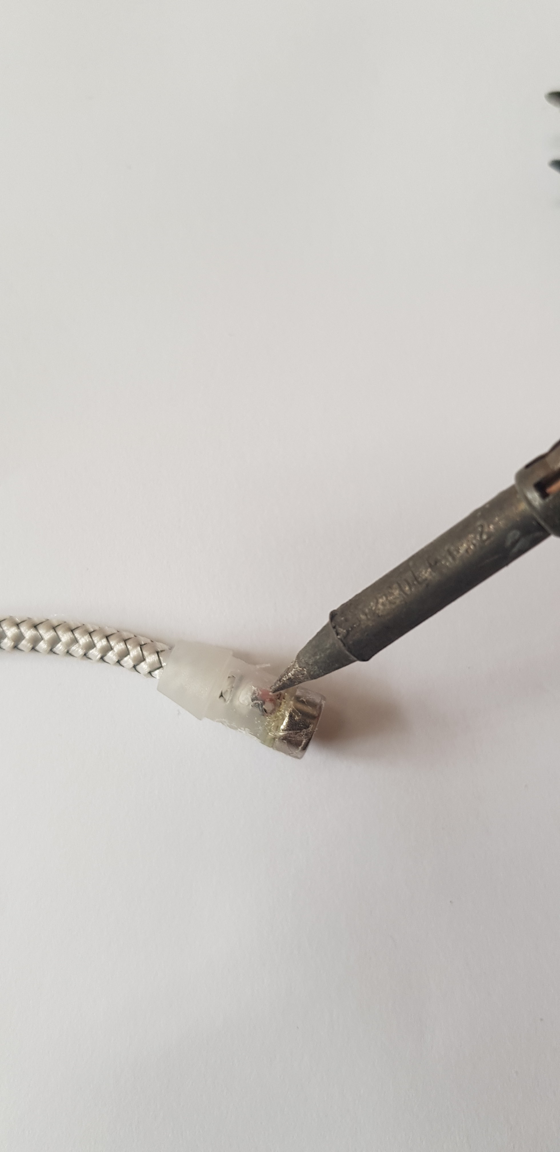
4. Remove the LED on the power supply connector with a soldering iron
![]()
-
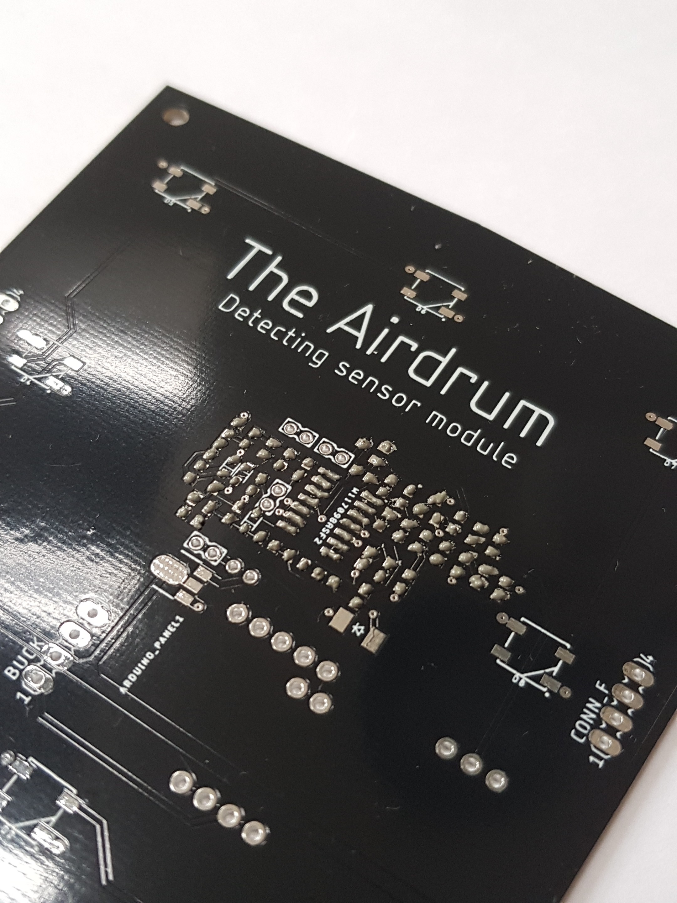
2The PCB
1. Append solder paste
![]()
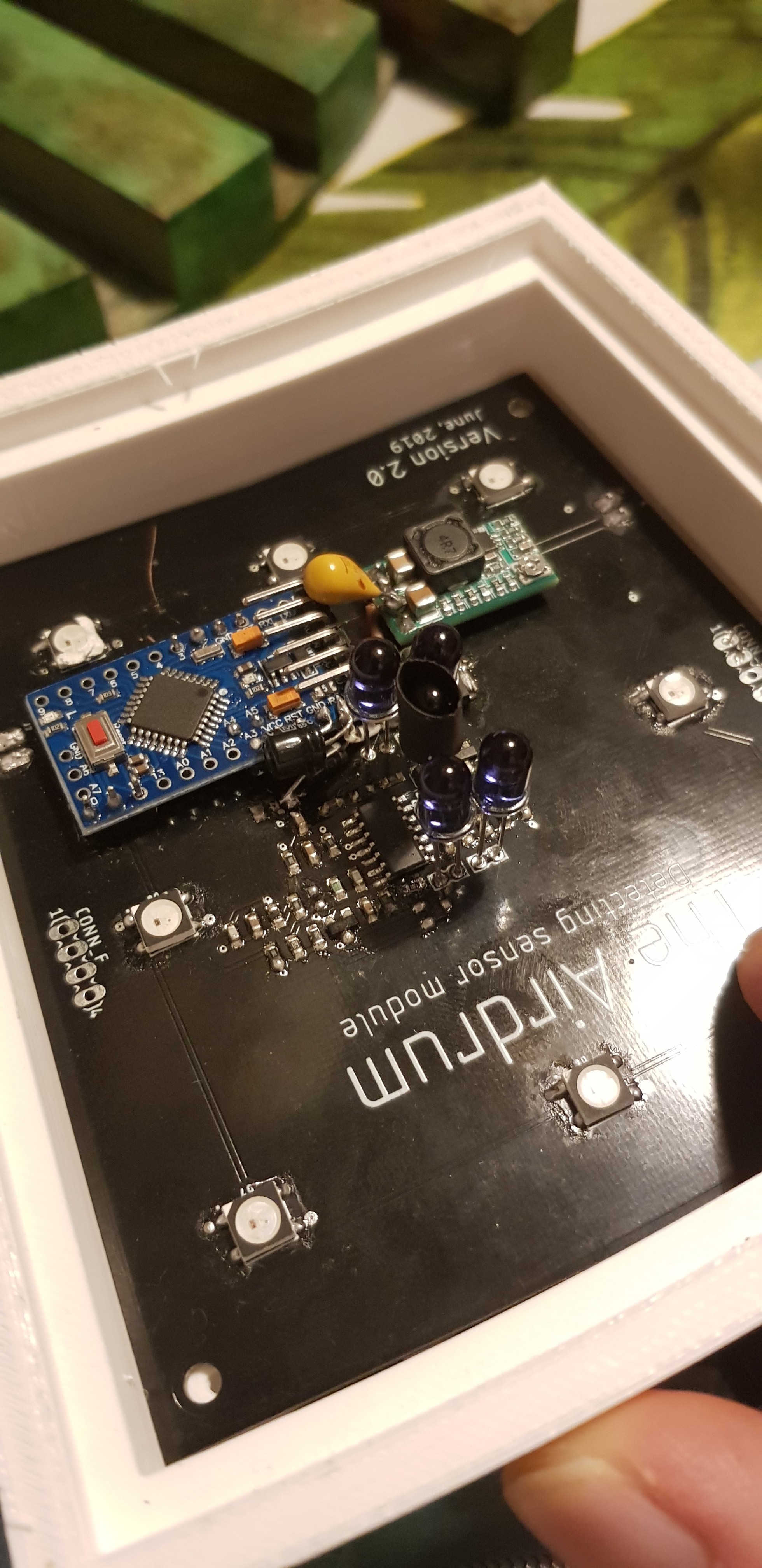
2. Place components, reflow the PCB and check connections with a multimeter (time consuming process)
![]()
3. Solder Buck converter, the arduino and the IR LED's in place. (3Dprint the LED holder STL file and use that to get the LED's in the right position)
4. Solder 8 WS2812b RGB LED's in place
![]()
-
3Add power supply wire for voltage drop reduction
To reduce the voltage drop we advice to add power supply wires on the bottom part of the panels.
![]()
-
4Panel power and data connections
Connectors need to be soldered on to the panels.
We're using female USB C connectors as mentioned in the parts list.
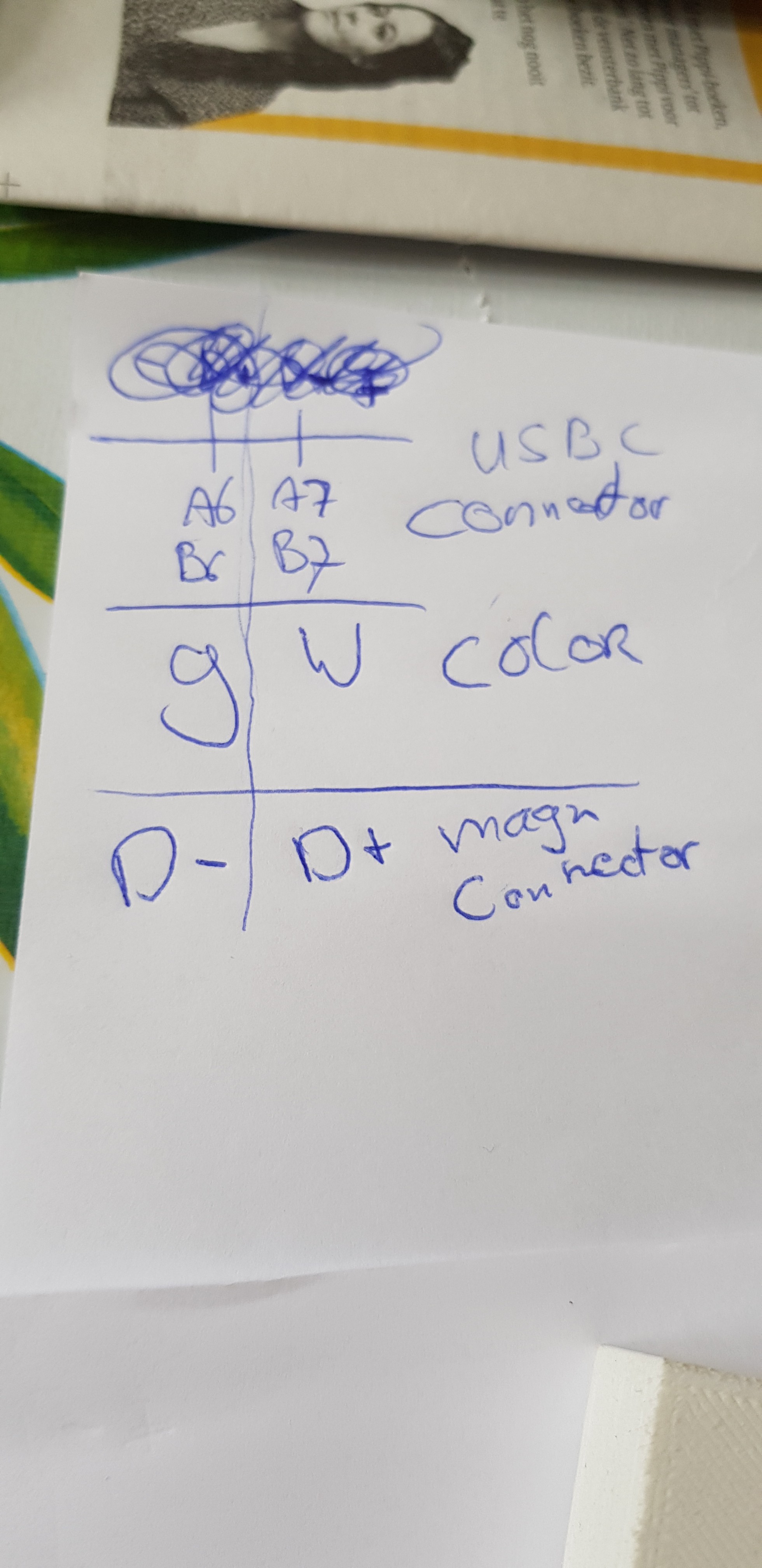
Data and audio:
A6 and B6 connect to the green wire of the Elough cables (i2c SDA line). A7 and B7 connecto to the white wires of the Elough cable (i2c SCL line).
The VCC of the Elough cable is used for audio.
![]()
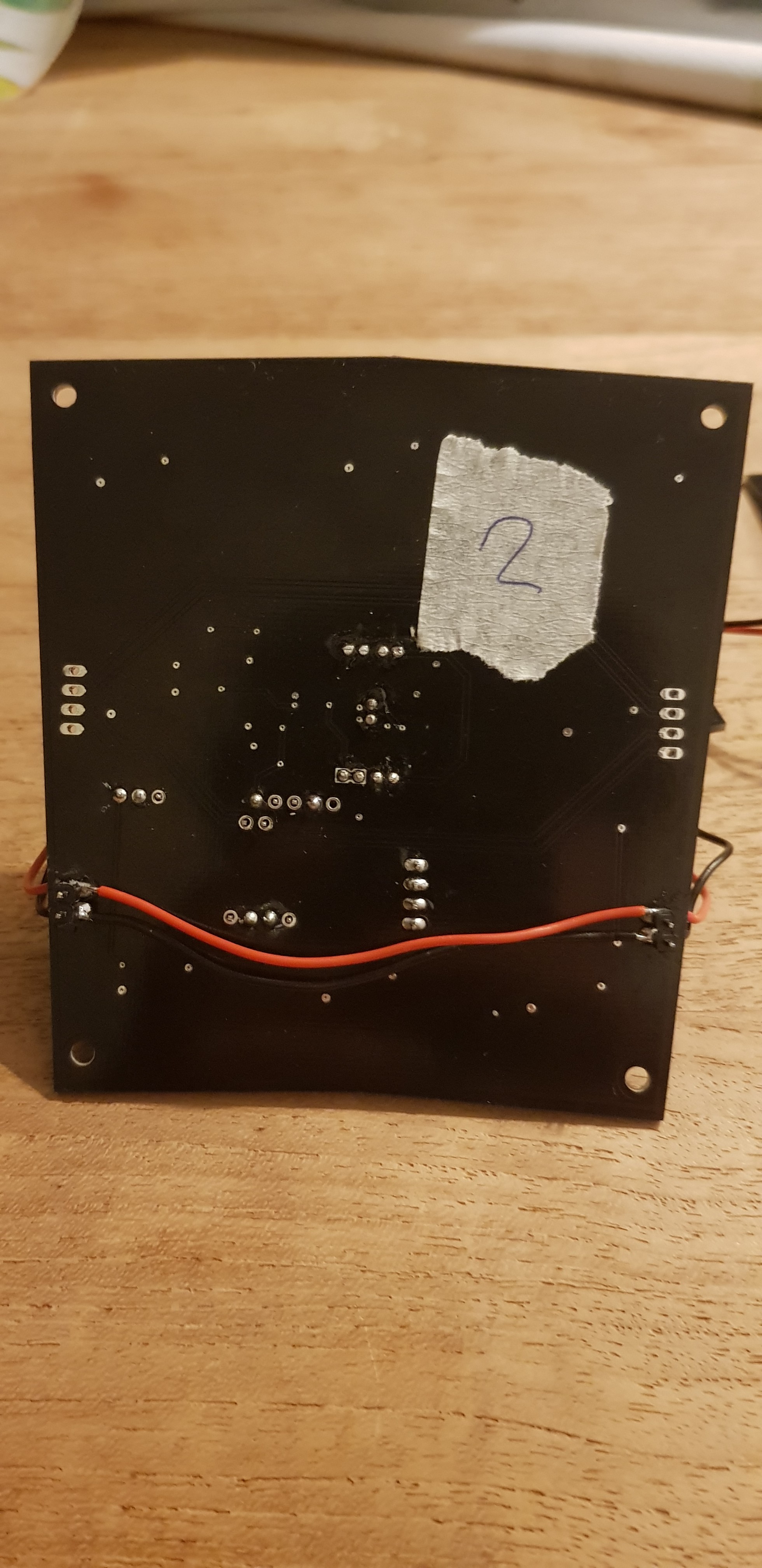
Completed panel connections:
![]()
Top left: USB C data connector
Bottom left: USB C power connector
Top right: stripped magnetic USB C connector
Bottom right: Stripped magnetic USB C power connector
-
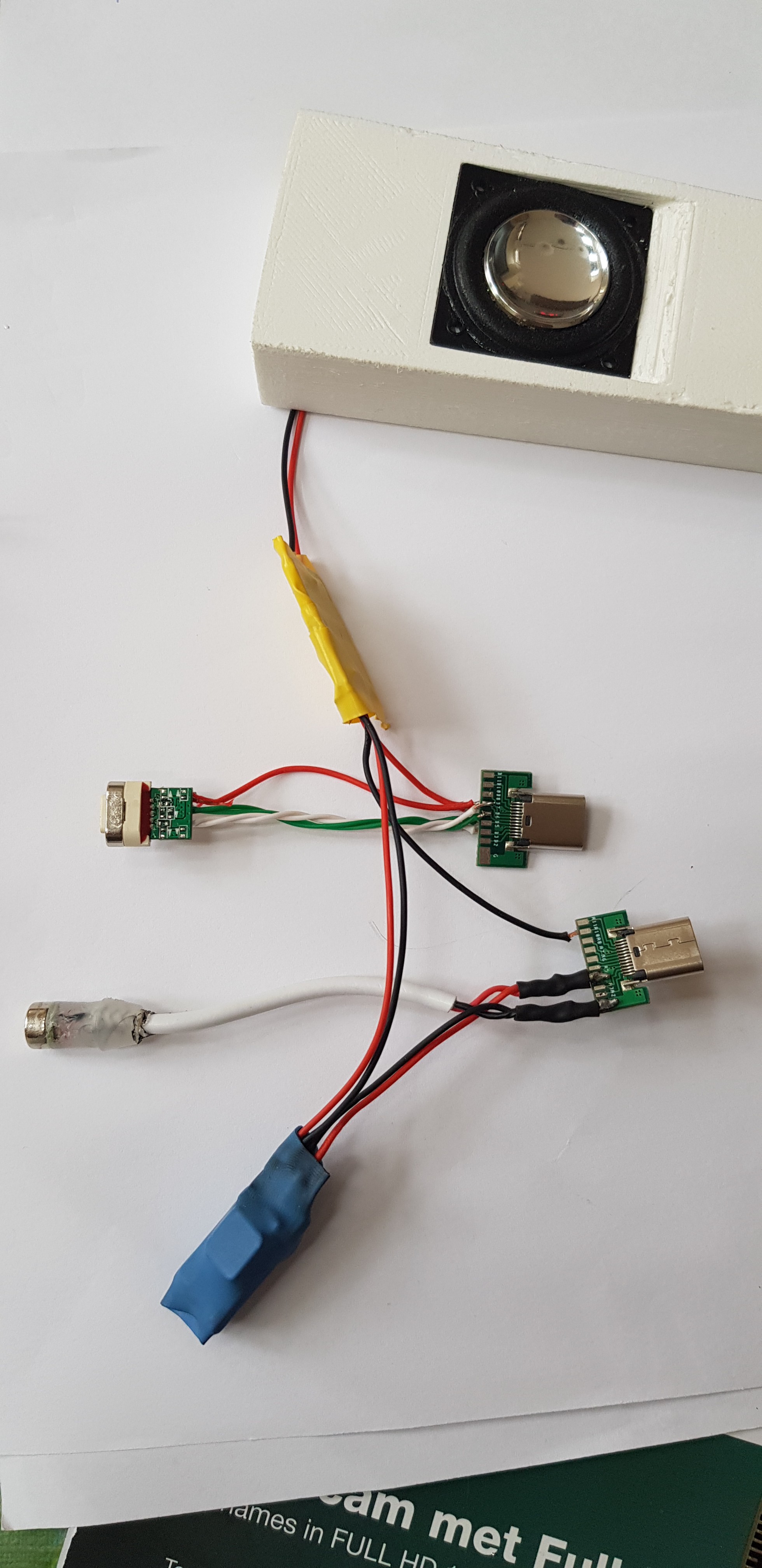
5Speaker modules
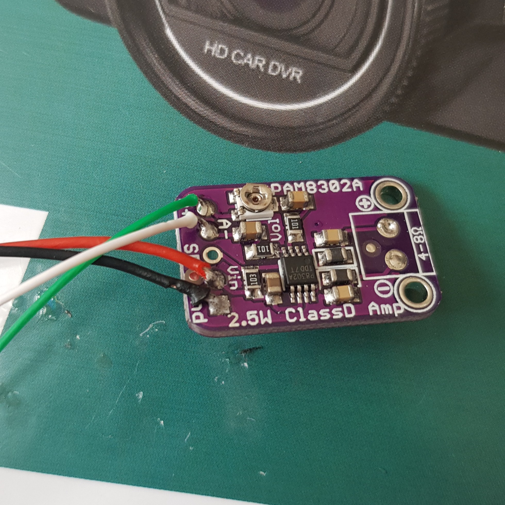
1. Solder the wires on the amplifier.
![]()
We've used the VCC of the data connector as audio source.
The PAM8302A needs a voltage of MAX 6Volts so we used a Buck converter to reduce the battery voltage.
The other wires are just to pass through the voltage and i2c lines.
2. Solder the other connections
![]()
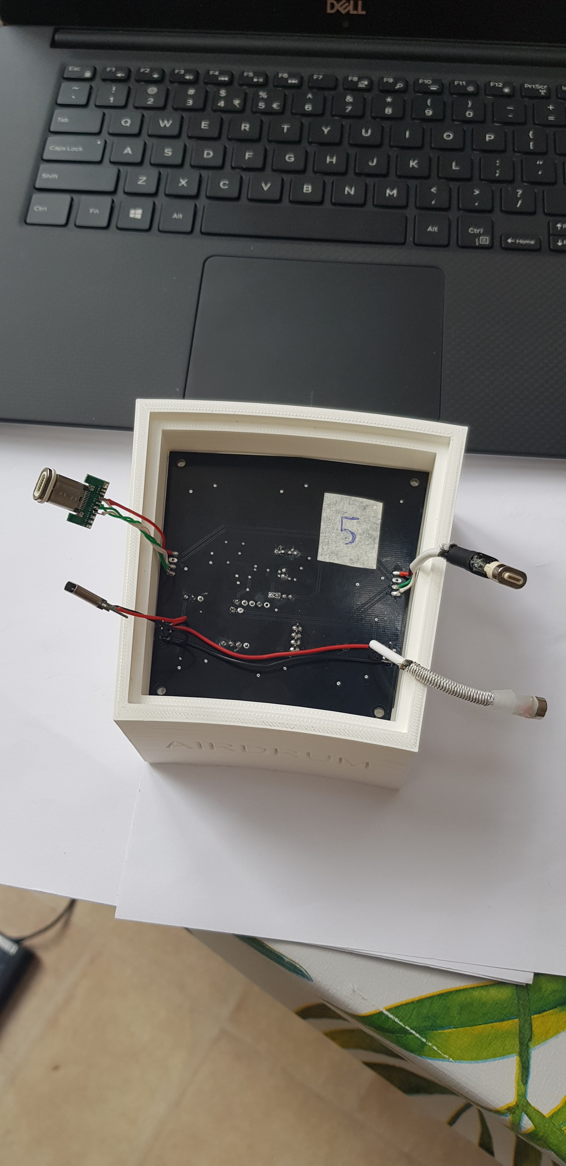
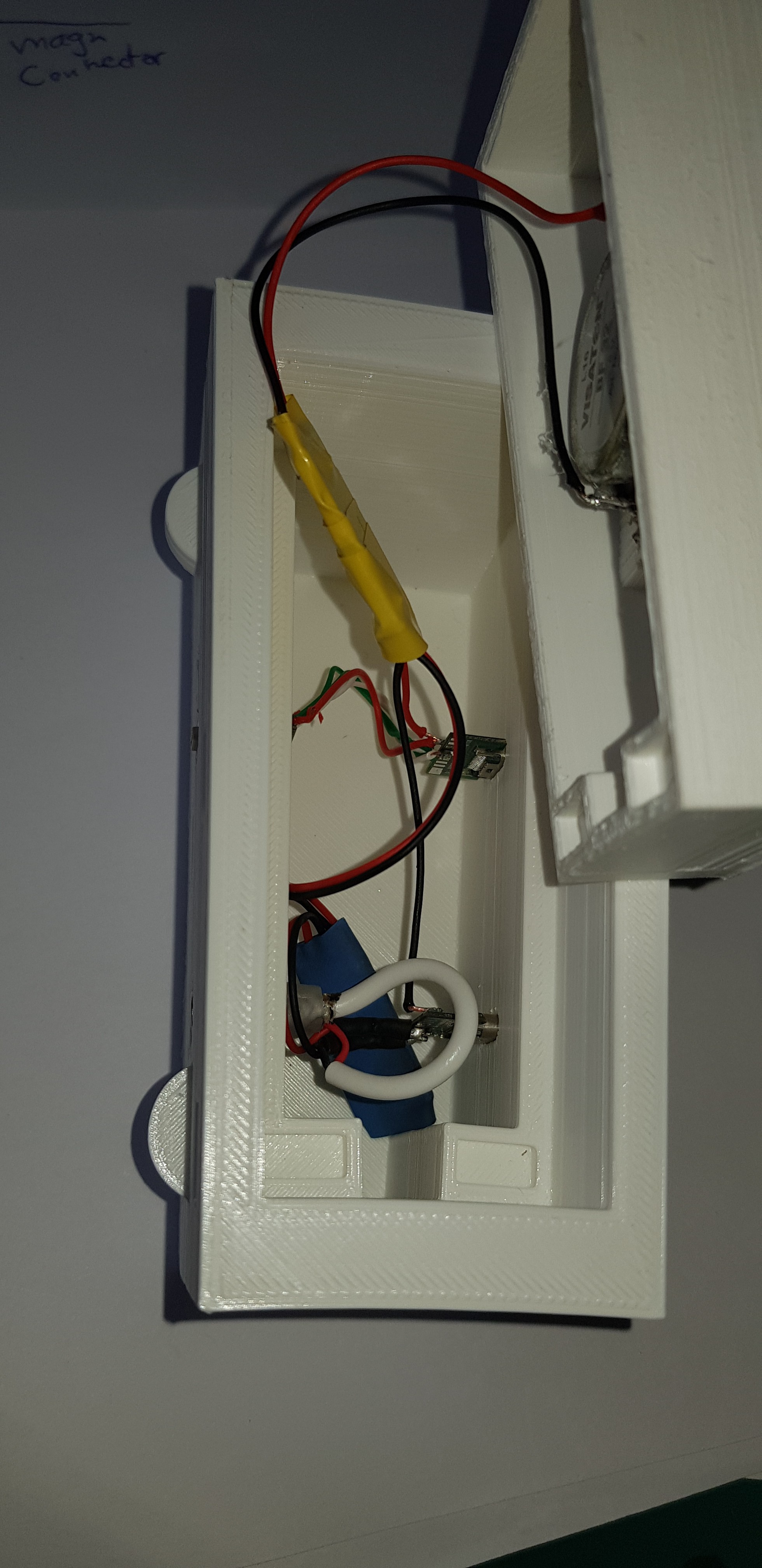
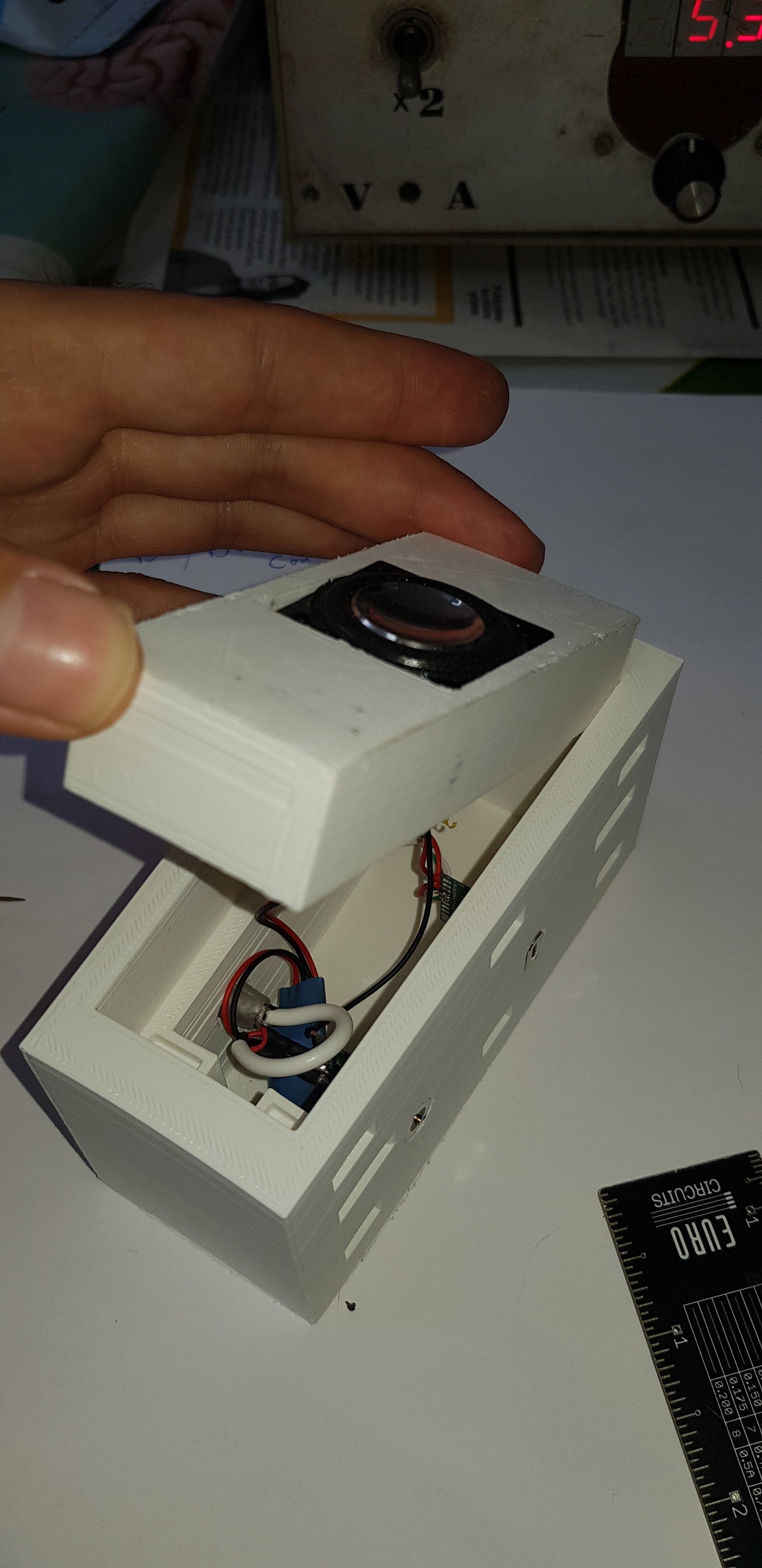
3. Place it all in the speaker enclosure
![]()
![]()
-
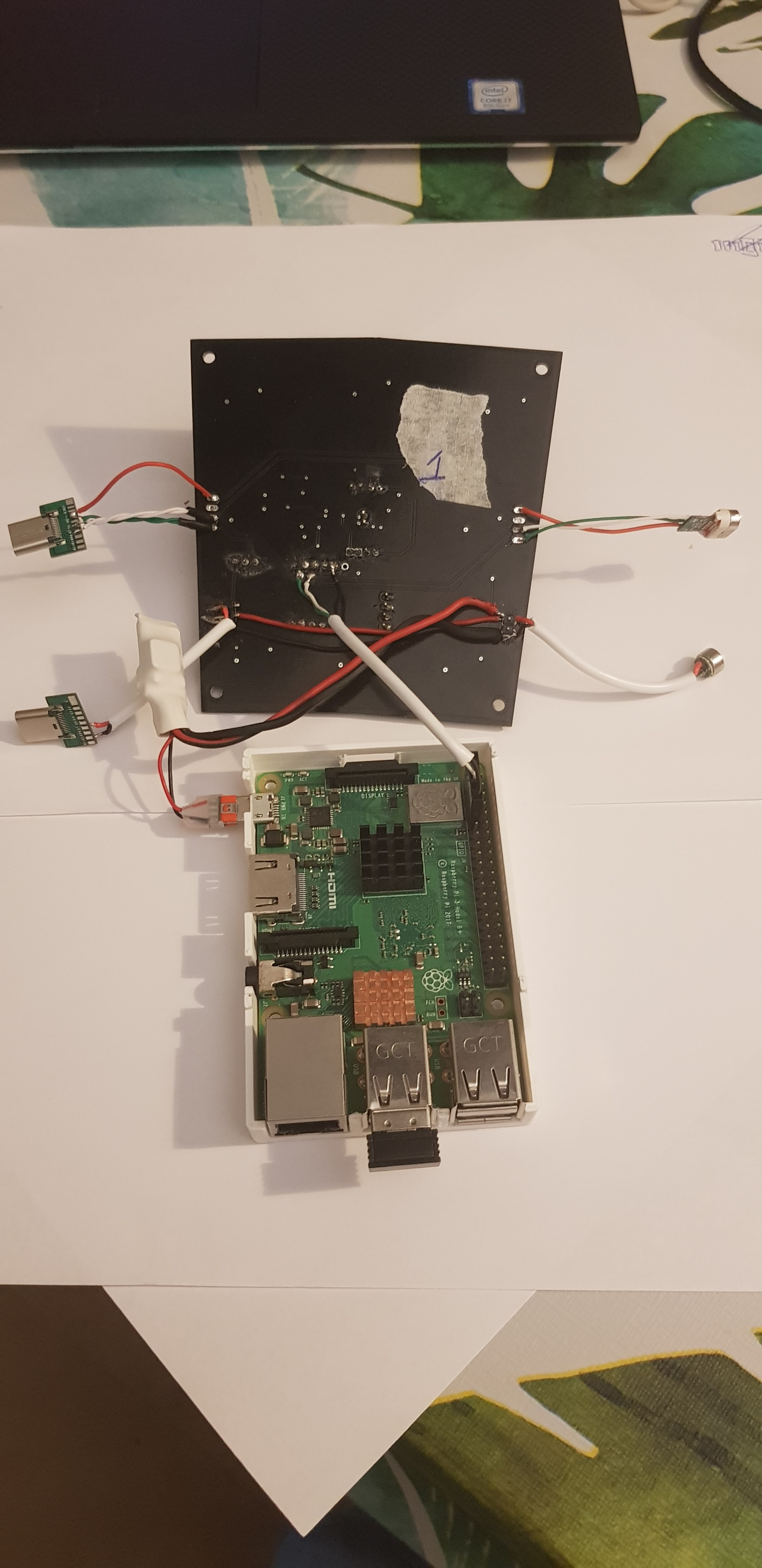
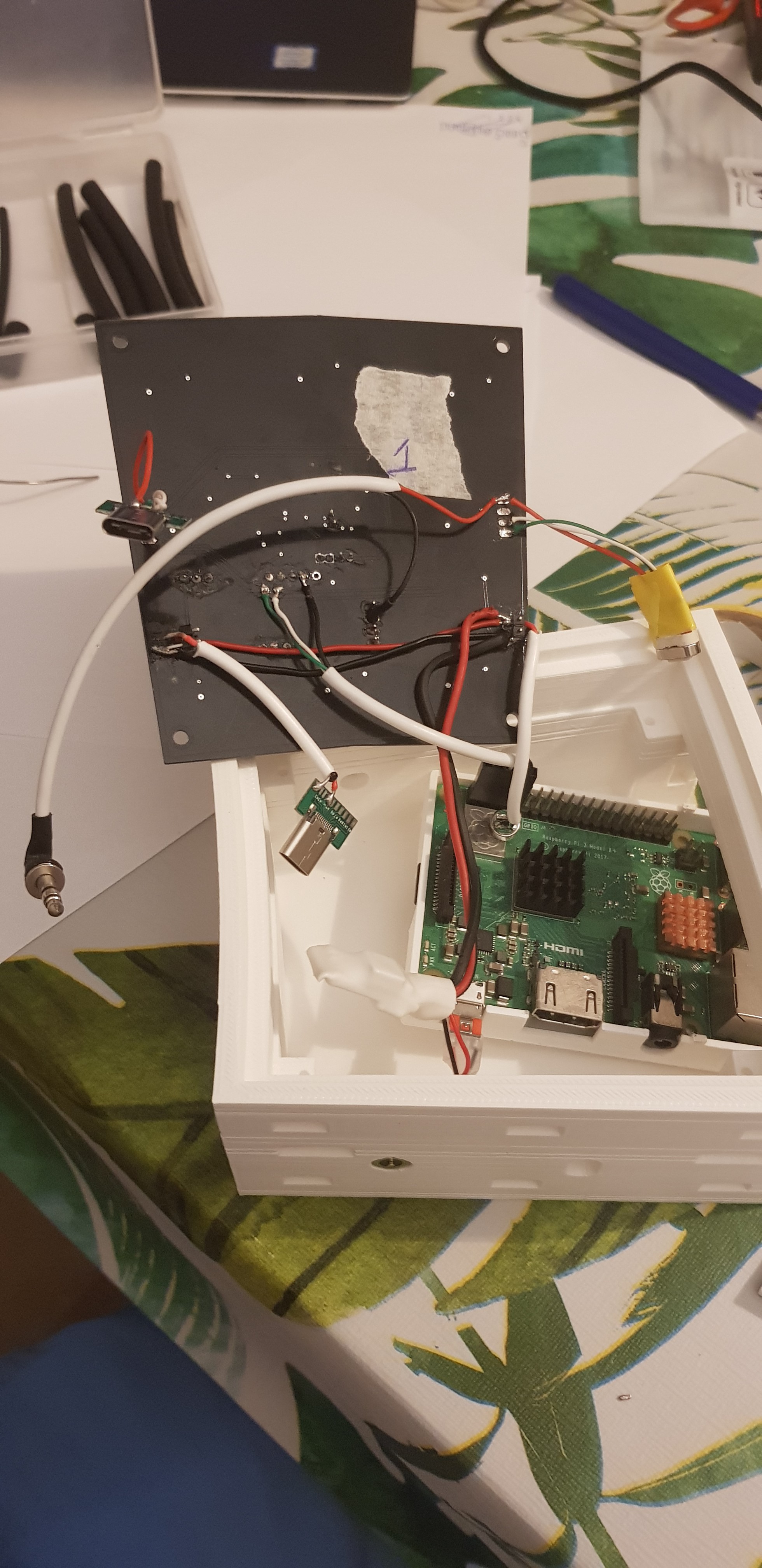
6The master module
We've designed the PCB in a way that all the panels are exactly the same.
The only difference is that there's a raspberry pi beneath the PCB as i2c master and that the aux connections need to made for the audio.
![]()
![]()
The Airdrum - Make music while moving
Auditive and visual feedback with minimal effort in a modular package for everyone!
Discussions
Become a Hackaday.io Member
Create an account to leave a comment. Already have an account? Log In.