alessandro verdiesen
-
From interpreted to compiled software
08/22/2019 at 15:25 • 0 commentsWe discovered that our software is to slow when its interpreted by the Raspberry pi in Python. We have some reasons to rewrite our program in C.
Request data from panels (arduino's)
The recent version uses python scripts to get the added or removed panels (i2c adresses) in a loop by using the i2cdetect library. This library is written in C.
Music generation
Sonic Pi is used to create the sound currently. Sonic Pi is a very cool application but it's quite a overkill for The Airdrum. That is why we've chosen to continue with Fluidsynth. Fluidsynth has great API documentation and is able to generate sound from MIDI like objects in C.
http://www.fluidsynth.org/api/index.html
Fluidsynth is great to be used by The Airdrum when we are adding the synthesizer functionality. It is also written in C.
It will be quite some work to combine both libraries into a single project, but it seems that this will be the best choice to create The Airdrum as we have in mind. This will enable The Airdrum to reach the speed that is needed to follow the end-users movement.
-
Debugging, patching and making the dream work!
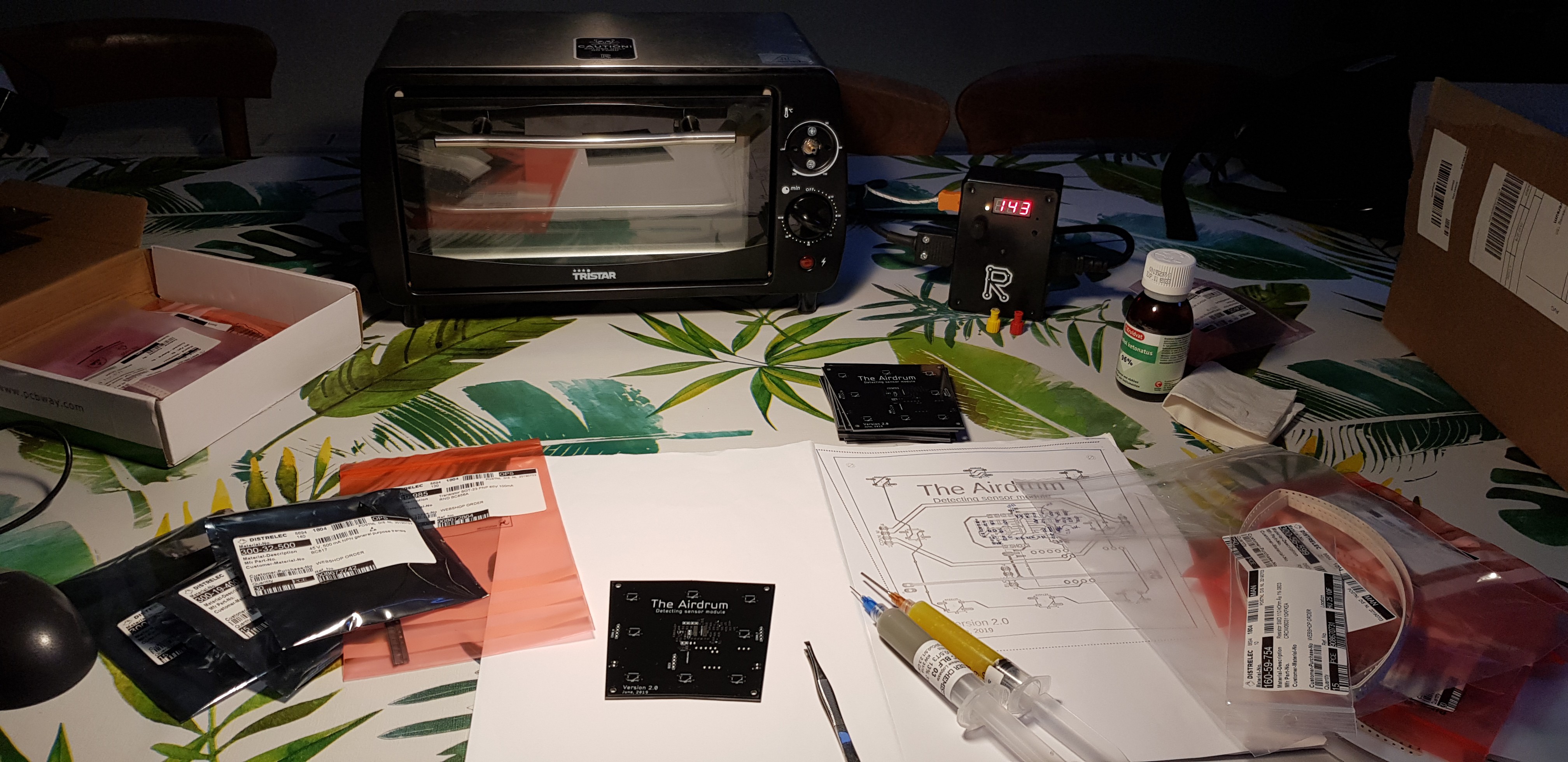
08/18/2019 at 16:17 • 0 commentsWe're working hard to build The Airdrum as we have in mind.
The project is going in the right direction (so far..)We're Learning every second and continuing, even with the immense challanges combining the software with the hardware.
As all engineers know.. Dreams are not built in a day.
We simply like to challenge ourselves :)
![]()
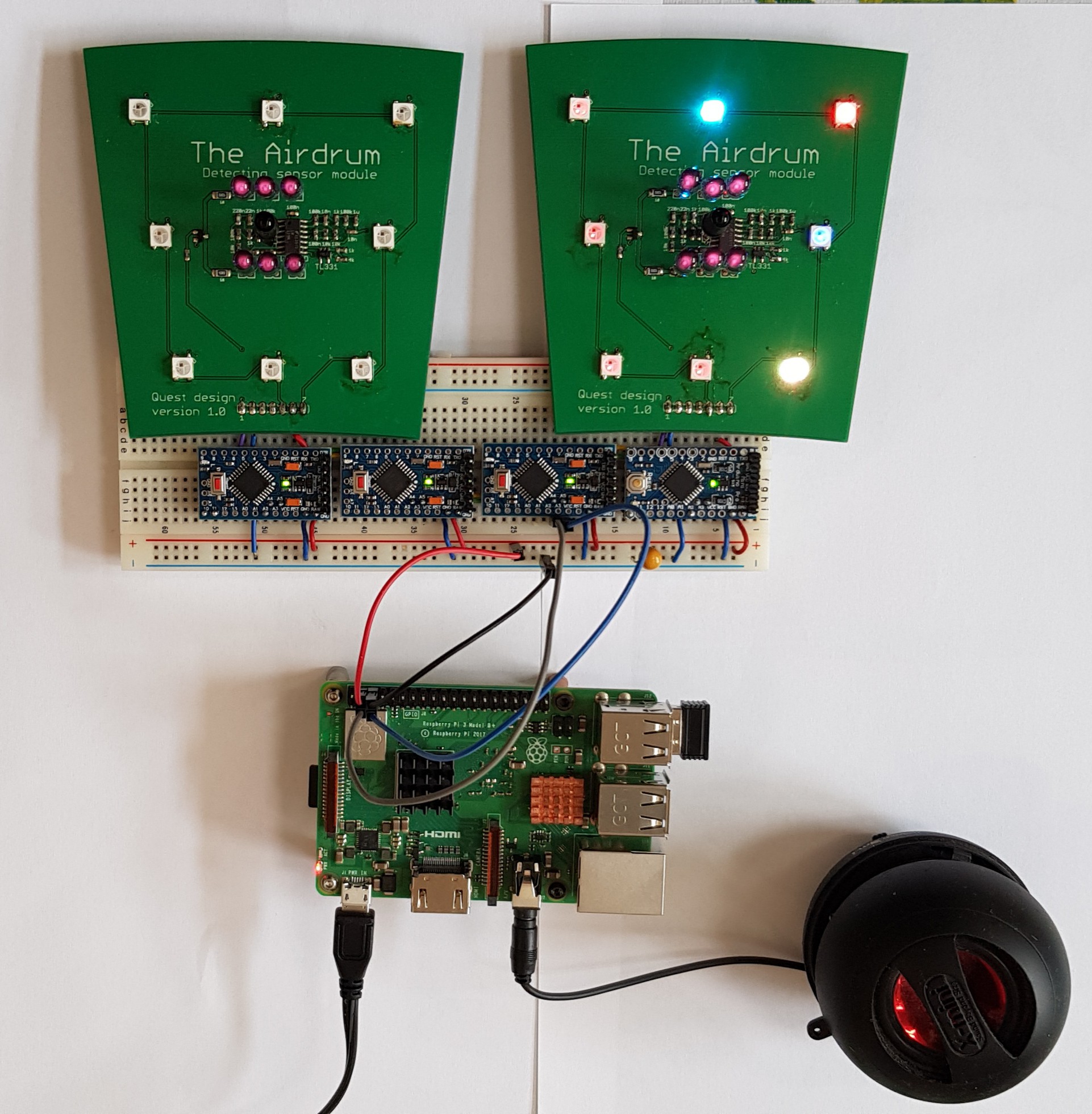
Testbench of the Airdrum:
- 4 Ardruino pro mini's as dummy panels, testing the speed of the i2c readings.
- 2 V1.0 panels as distance sensor and visual RGB feedback
- A simple speaker for the auditive feedback
Things we have acomplished so far..
- We are able to generate random adresses on the 328P MCU's so that all the panel MCU's have an unique i2c adress while the Rpi is booting up.
- Get the analog value from the IR distance sensor of all connected panels in a loop from the Rpi (everything is rewritten in C for a massive speed improvement)
- Generate sound from a MIDI variable array in software using Fluidsynth synthesizer with variable soundfonts
Things to work on..
- play a tone with the IR distance sensor as trigger
- do something with the distance in the tone to play (synthesize the sound with manual manipulation)
- Set the panel colors from the Rpi
- Combining all the parts
- Cleaning the code for faster IR distance sensor value readings
- Start the IR transmitting LED interrupt for the blinking IR transmitter when the i2c interrupt occurs. (saving power)
-
Quick demonstration of our prototype
08/06/2019 at 18:16 • 0 commentsWe finally can show you a short demo of our prototype. This version is fully modular, has a greater range, has faster response time and can be built into a full circle.
-
Input and Output panel for the base module
08/05/2019 at 01:15 • 0 commentsPowering, charging and checking the battery of The Airdrum!
We've succesfully designed and printed a panel for powering and charging The Airdrum.
With the a battery voltage indicator we're also able to see the percentage of the battery module.
![]()
-
Decrypting a thoughtful idea into tangible reality
08/01/2019 at 12:39 • 0 commentsWe have started a Github page!
Since this project is in high pased development at the time of writing, the repo is constantly being changed.
Don't hesitate to take a look if you're interested in the software :)
https://github.com/alehanderoo/Airdrum
We're working hard to pull this off!
-
Melting plastic!
08/01/2019 at 12:27 • 0 commentsWe have started printing the panel modules
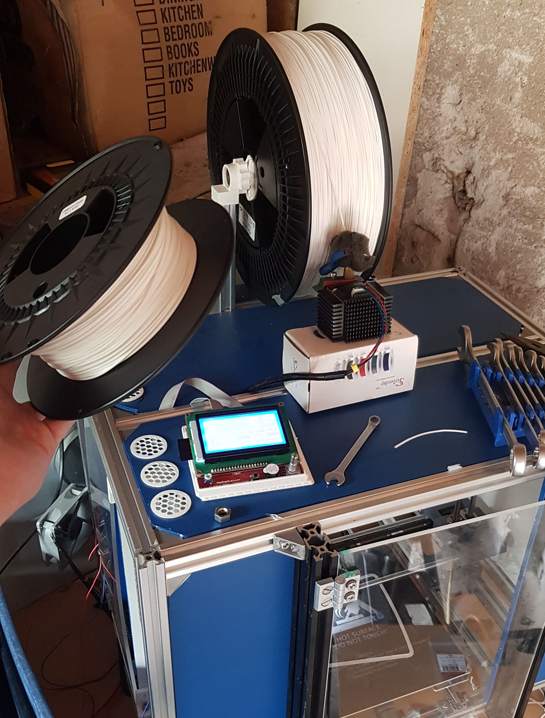
With the arrival of a new rol of filament it's time to start printing.
![]()
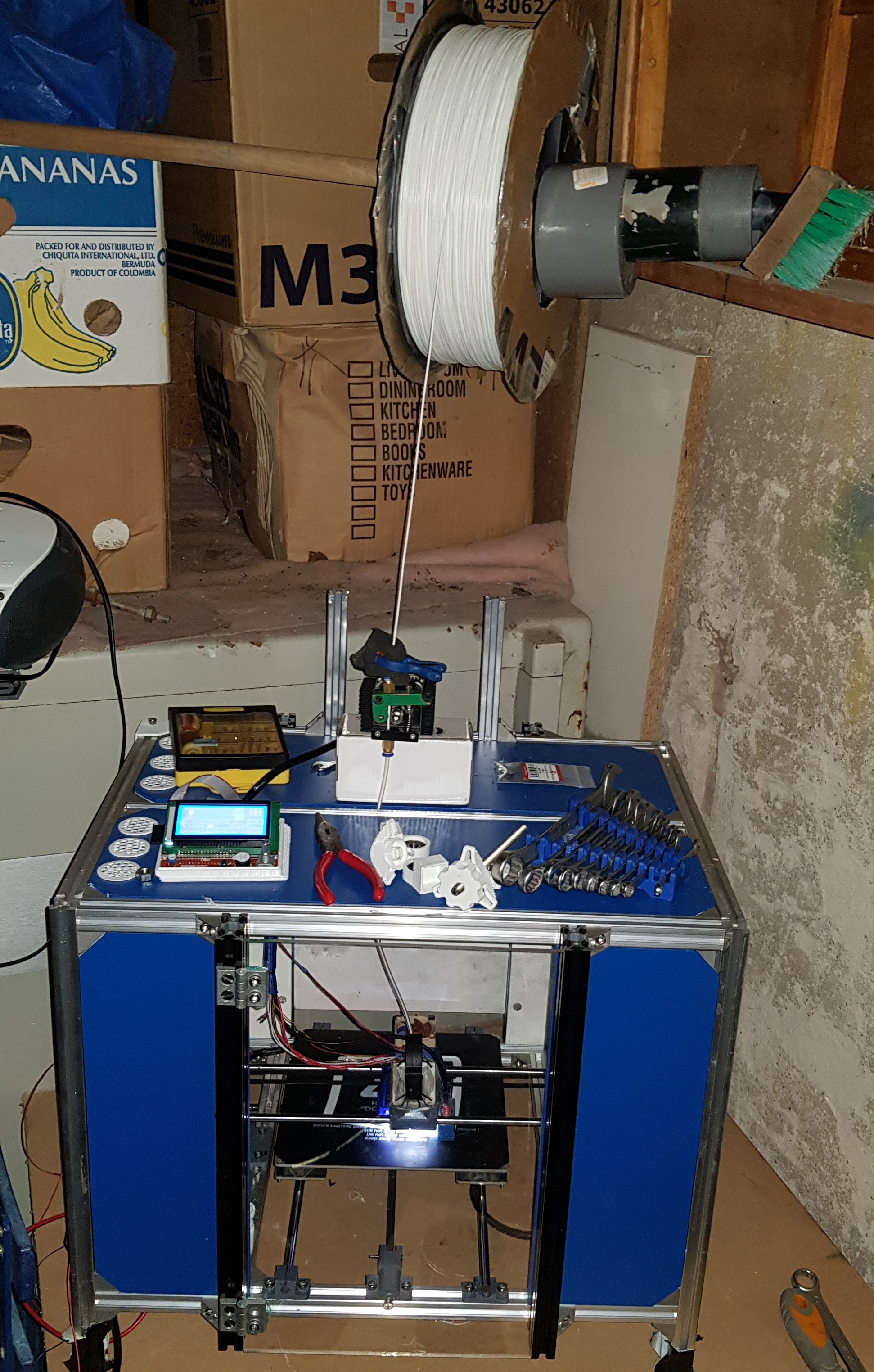
Drastic measures are taken to optimize the filament guidance
![]()
Teamwork makes the dream work!
![]()
-
Sound from The Airdrum
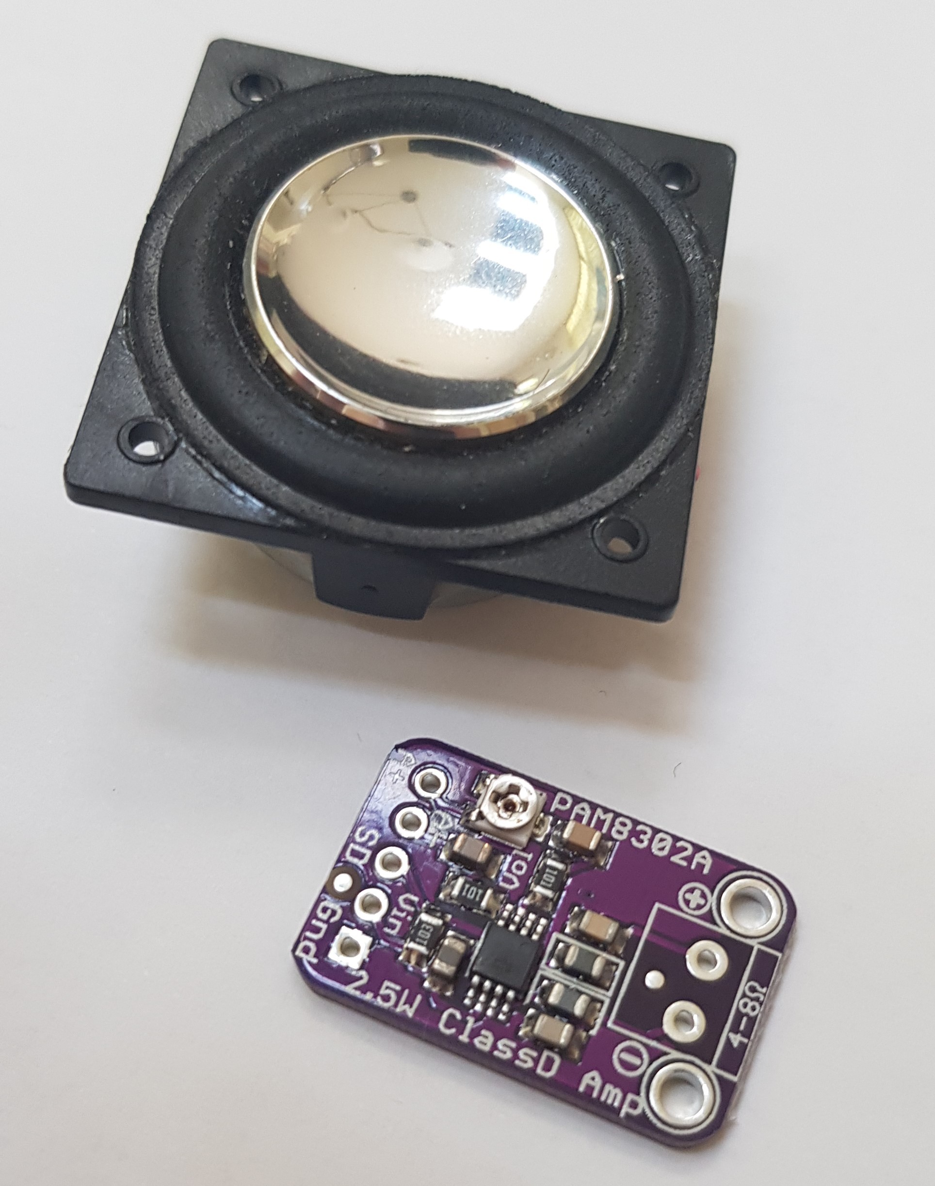
07/25/2019 at 10:57 • 0 commentsThe tiny speakers also arrived. These Visaton BF 32 3.2 cm 2 W 8 Ω speakers are perfect for the prototype because they can be fitted nicely in the case. They have a Powerful neodym drive and so be powerful enough to be driven by a small amplifier.
For the prototype we decided to drive the speakers with a mono amplifier. These modules are widely used and produce acceptable sound quality for this prototype.
![]()
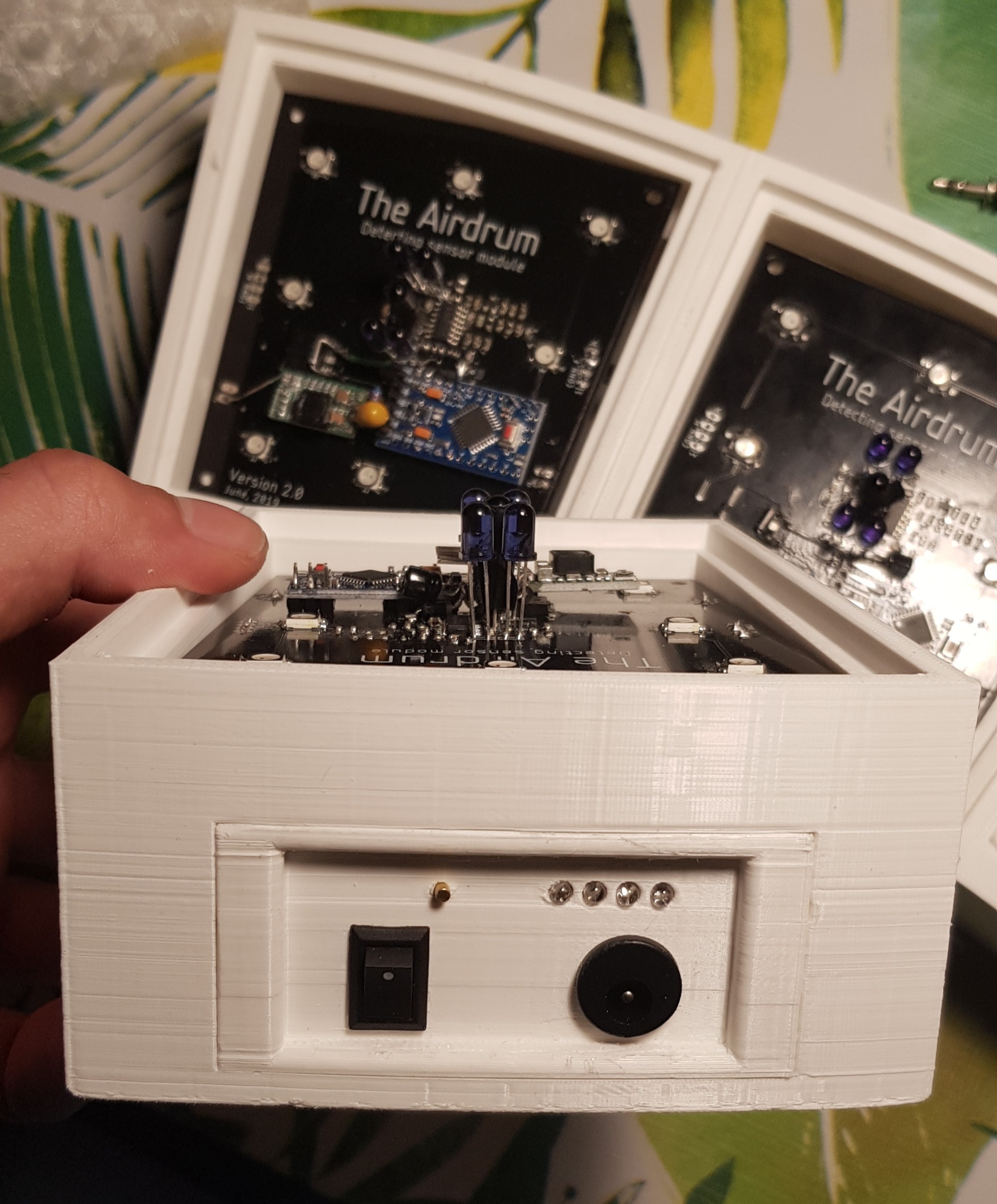
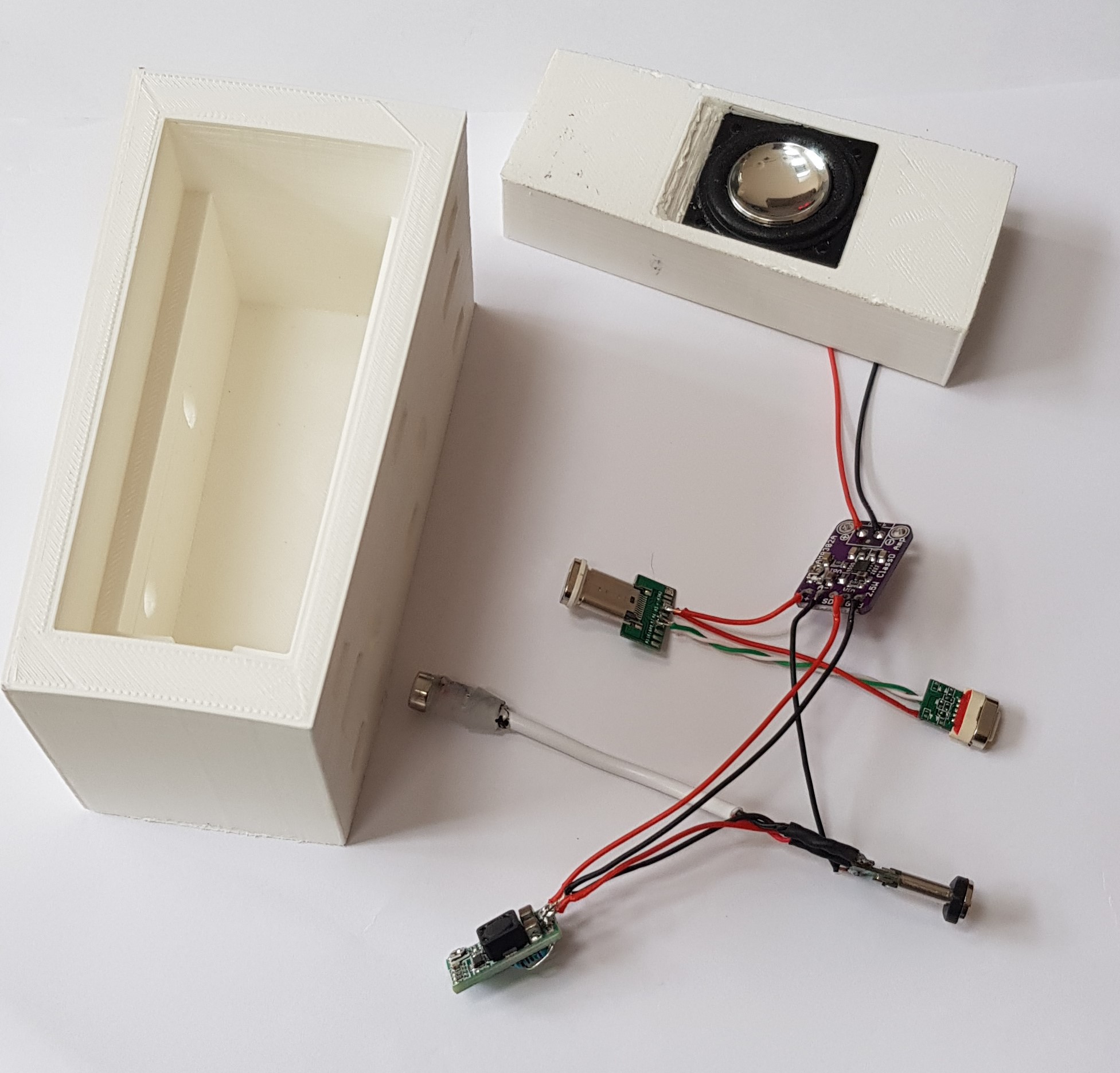
Picture of the 3D printed casing with wiring and electronics.
The speaker module is half the size of the normal base module. The module can be powered from both sides and will pass the i2c data to the other side(connector). This enables the end user to place a speaker module in between two hand detecting modules, a couple of speaker modules in series or even a speaker module alternately to other modules. That's the beauty of a modular design :)
![]()
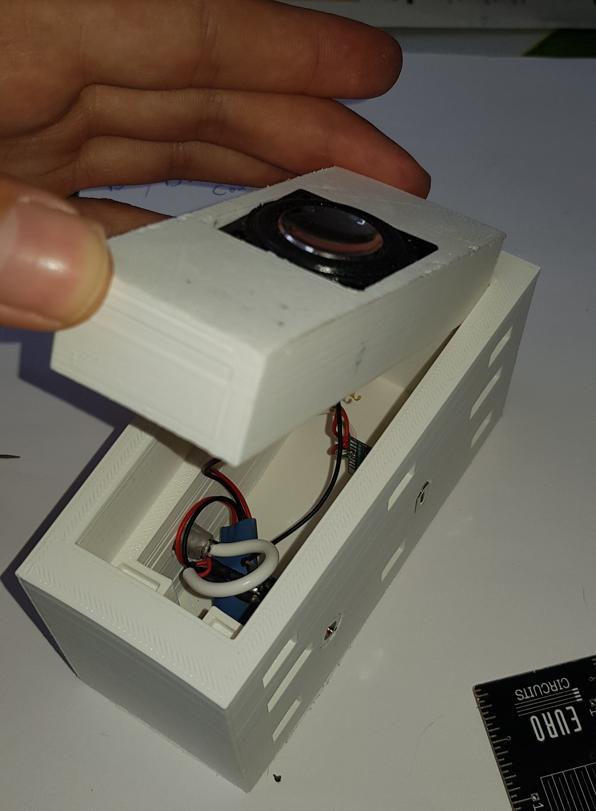
The picture below shows all the needed components fitted nicely in the module.
Some of the parts needed protection from touching other components. The Buck converter and amplifier are therefore encased with heatshrink.
![]()
-
The Airdrum sensor panel
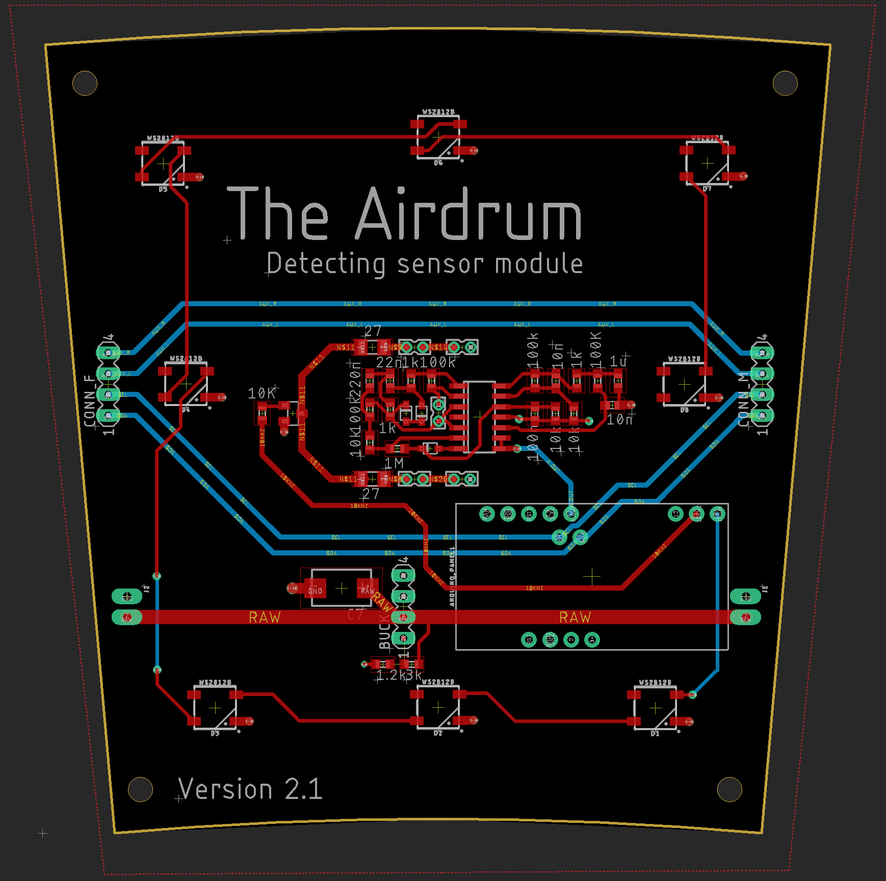
07/25/2019 at 00:59 • 0 commentsThe board
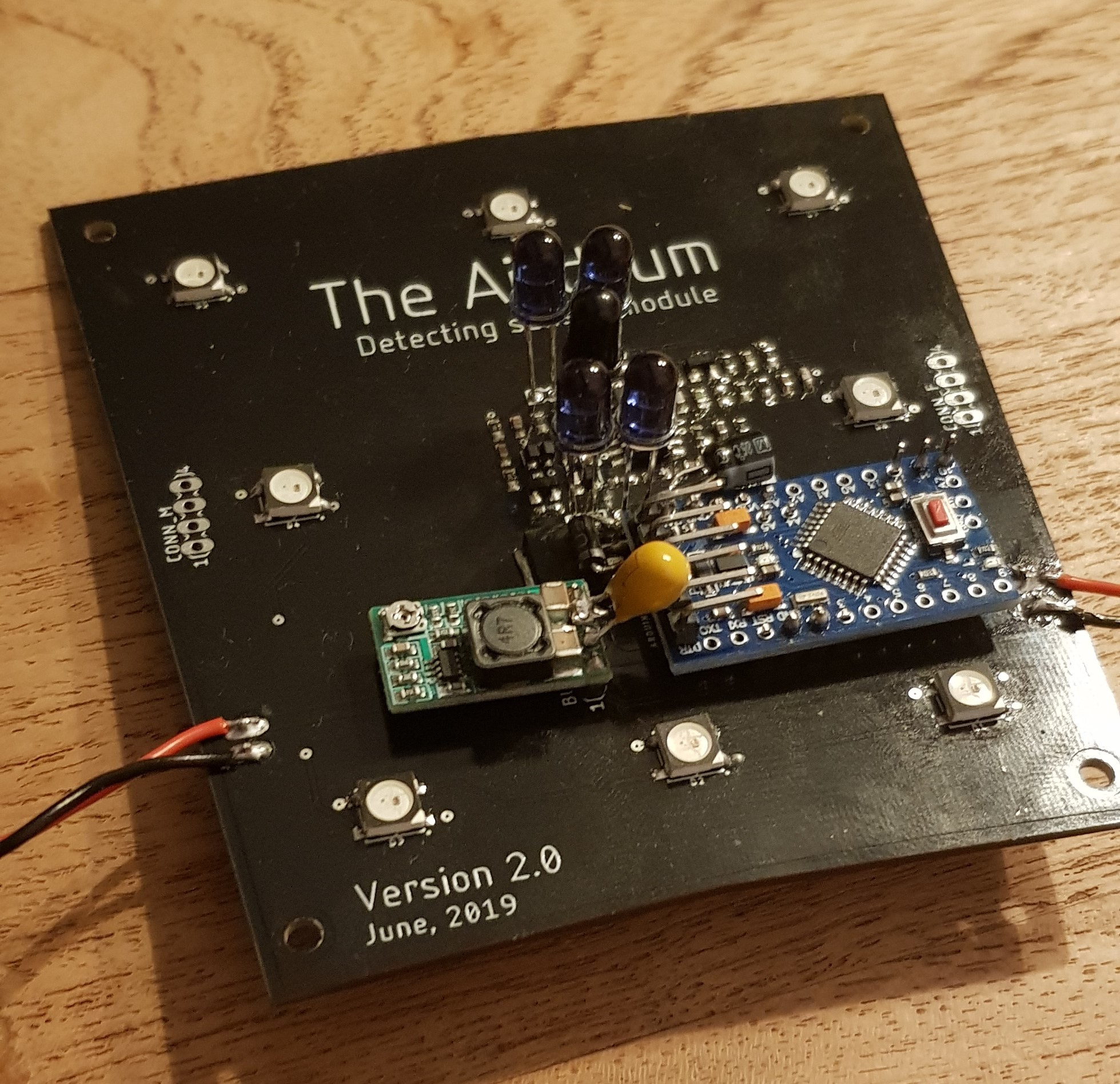
After designing the schematics in LTspice we designed the pcb in Eagle. With the modular design in mind we decided to go for a PCB with it’s own processor and Buck converter.
The Pro mini is placed to make the panels individually addressable for data transfer to the master synthesizer. It will drive the IR-Tx LEDs, drive the WS1228B digital RGB LEDs and read the analog input coming from the analog detection sensor.
The Buck converter is placed to reduce the current through the 16V power lines of the panel.
The PCB is 10 degrees in width to be able to fit in the casing and the RGB LEDs are placed like the previous version.
![]()
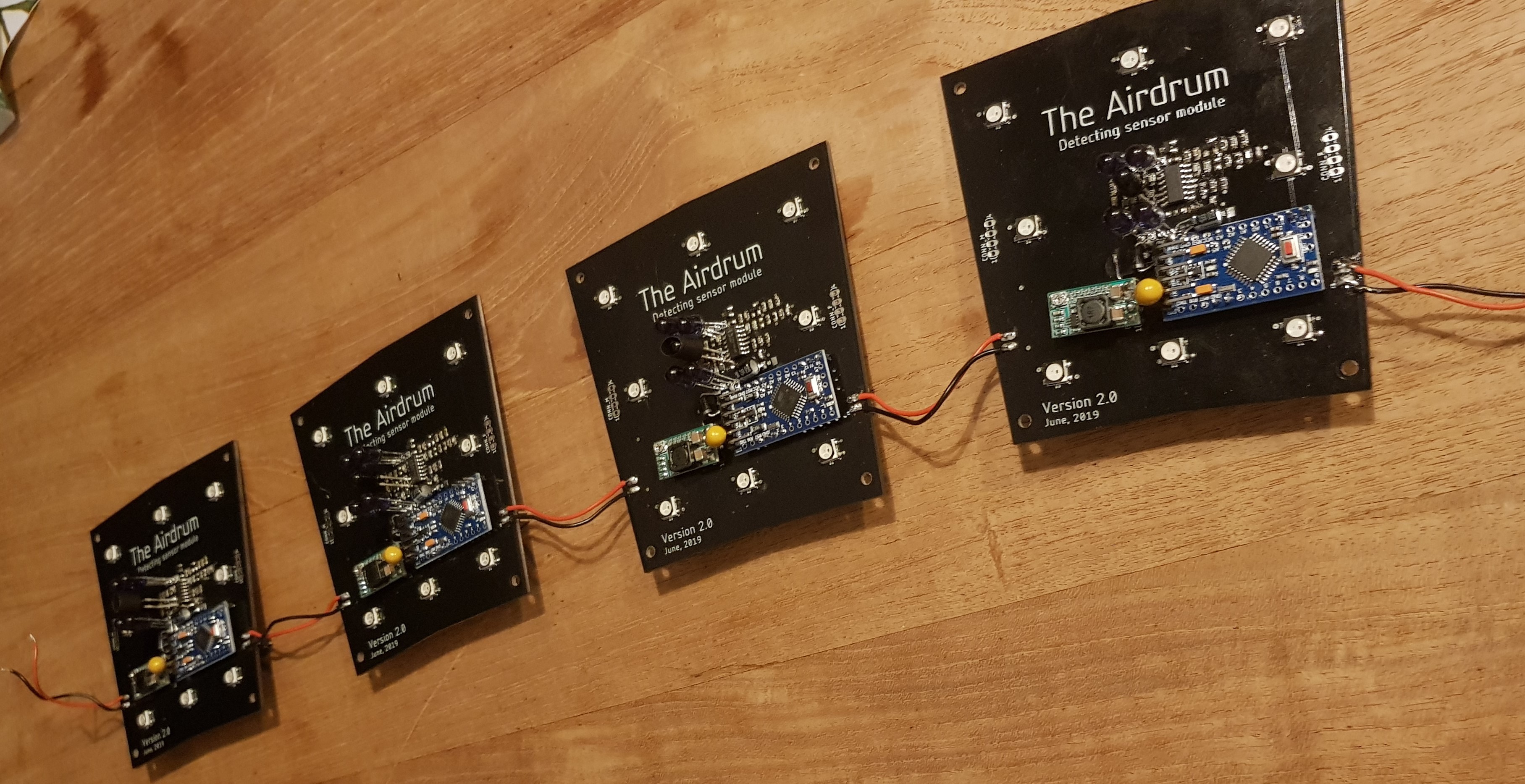
Placing all the components and reflowing the solder paste.
![]()
First 4 prototypes
![]()
Decoupling capacitor
When coupling or decoupling a panel to The Aidrum the power lines will get voltage spikes. To protect the circuits for these electrical transients we have placed a 22 µF tantalum capacitor over the RAW and GND lines of the panel. This capacitor wasn't placed on the board we ordered, but it is placed in the uploaded V2.1 schematics.
![]()
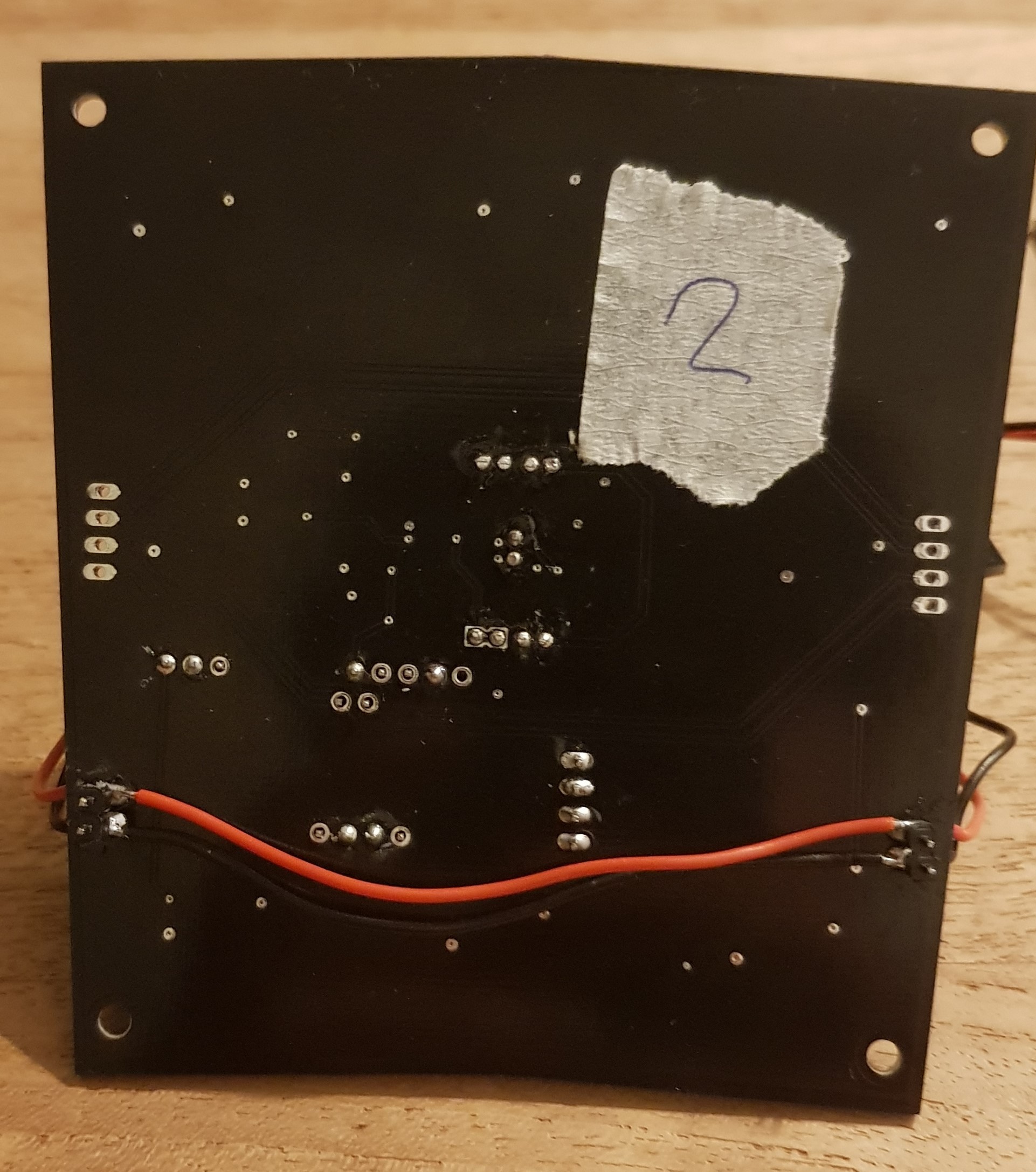
16V power line
Each slave panel (No Rpi3) uses 100mA when the Tx IR Leds are sending. The panel with the RPi3 included draws around 300mA. For this prototype the decision has been made to order PCB’s with a copper thickness of 1oz/ft2 to reduce the cost per panel.
Even in a single battery, almost full circle configuration (one missing panel in the full circle, therefore making the longest battery-panel trail) the width of the RAW traces are enough to power all panels. This is excluding all the magnetic connectors and USB-C converters in between the panels. To reduce the voltage drop in the power lines we have included an extra wire beneath the PCB.
![]()
-
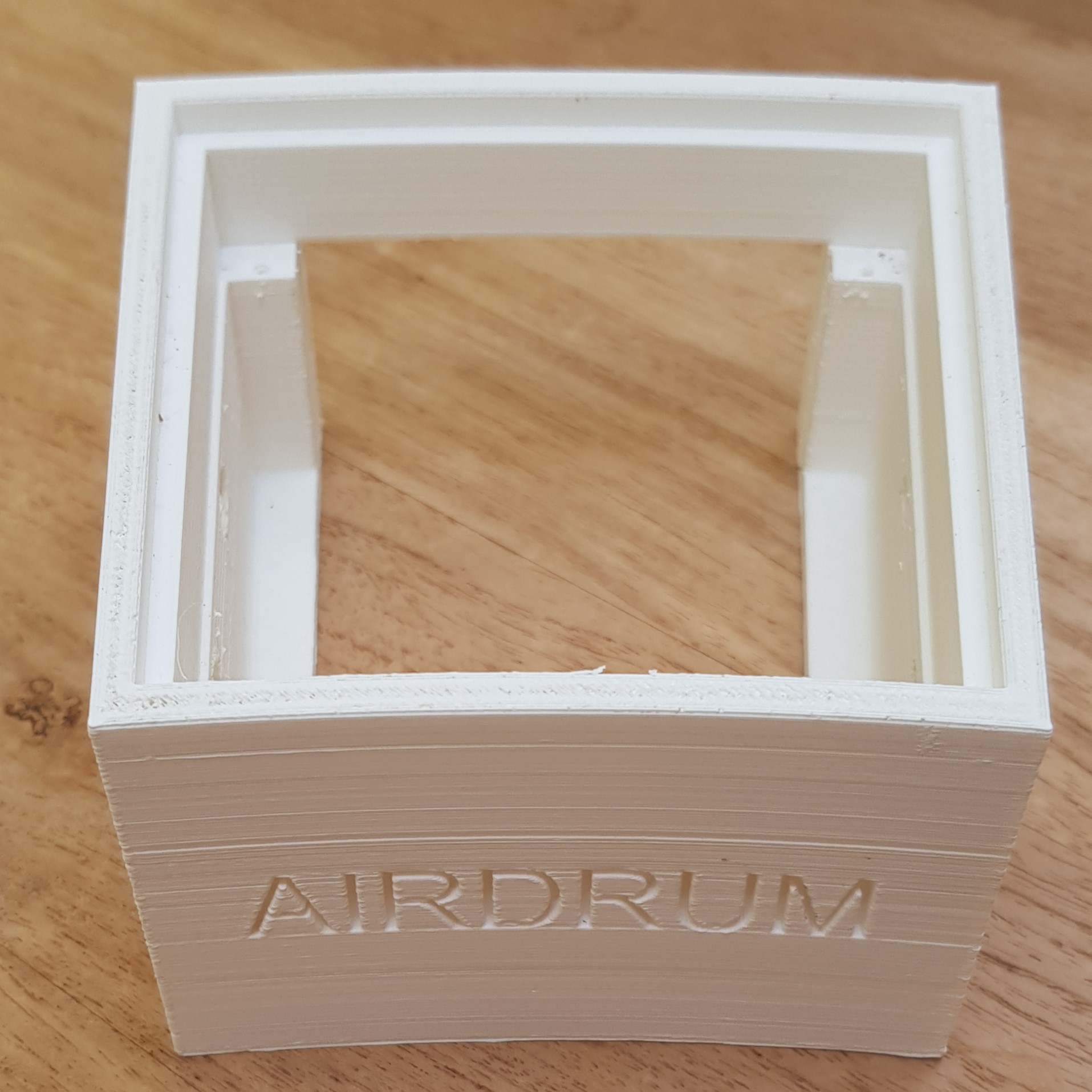
Creating the case
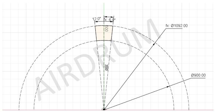
07/24/2019 at 13:43 • 0 commentsFor the initial version, we planned to use one single case for six panels. Because we were reliant on 3D-printing for prototyping, we had to cut the case in pieces due to the dimensions of the printer bed. During this development we came up with the idea of making the Airdrum a modular concept. For the current version we opted to redraw the case from the ground up. We started using Fusion 360 instead of SolidWorks.
We’ve changed the angle to 12 degrees. With this angle we can use 30 (!) panels in one circle, eventually with additional speaker panels. The inner radius is 450 mm. This is about an arm length.
![]()
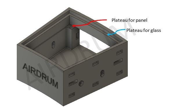
The concept
One pcb can be placed in the panel. On top of this pcb, a piece of glass can be placed. As you can possibly see, the case lacks a big part of the back. This is because we want to easily access the raspberry pi and arduino or battery pack during prototyping.
![]()
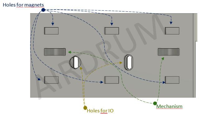
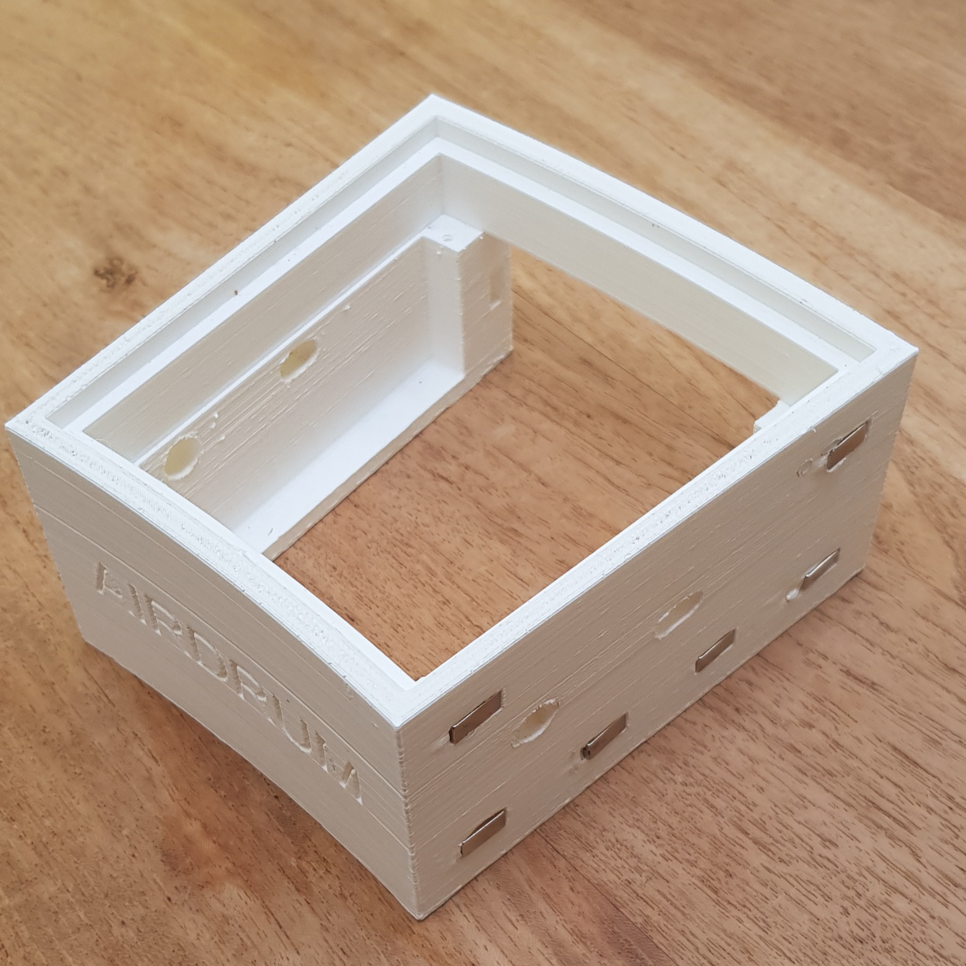
Holes
On the sides there are two holes. These will contain the magnetic ports. The six square cavities are for small magnets so the two panels will easily snap together. Furthermore, on the left side are two half circles. These fit in the two gaps on the right side. This mechanism prevents the panels from sliding vertically.
![]()
3D-print
Below you can see the 3D-printed version of the case:
![]()
![]()
Here is a video of the how the panels will snap together with magnets:
This concludes this log about the case. We’ll try to update regularly. Thank you very much for liking and following the Airdrum. We can’t wait to show you a prototype.
-
Detection
07/16/2019 at 23:00 • 0 commentsHand-detection
The sensor is realized with the reflection of infrared light photons. The sensor contains infrared transmitting and infrared receiving LEDs. These will be named as sender and receiver from now on.
There are serval things that are being kept in mind during the development of the sensors:
- The sensor must not interfere with other sensors. This means that the light from the adjacent sensor should not be picked up with reflection from the next plane.
- The sensor can detect objects to approximately 30cm (≈ 11,8 inch).
- The signal has an analogue output. The sensor will be designed so expansion in later upgrades are possible.
The circuit is designed so it can operate at 5 Volts because the hardware (Arduino, Raspberry and amplifier) also operate at this voltage.
Transmitter
For the transmitting LEDs, it is important that they all have the same transmitting power. We decided that LEDs will flash with a frequency of around 7 kHz. With this frequency, other sources (e.g. sunlight, 50Hz grid lighting) will not cause any interference. The LEDs have a wavelength of 940nm. The LEDs will be controlled with an interrupt on the Arduino board.
Receiver
![]()
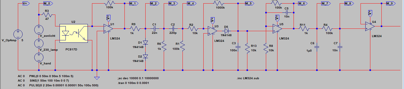
The receiver uses a quad opamp as main part. With reflection of the infrared light on a hand or object, a photodiode will conduct. This conductance is then used to create a voltage on the output of the first opamp.
We used LT-spice to simulate the infrared light that is reflected on a hand or object. A photocoupler is used to simulate the transmitting and receiving part of the circuit. This is a diode and a transistor that can simulate the transfer of infrared photons. The number of photons transferred from the diode to the receiver ensures that the receiver is 'opened'. The photocoupler is indicated with U2 in the circuit.
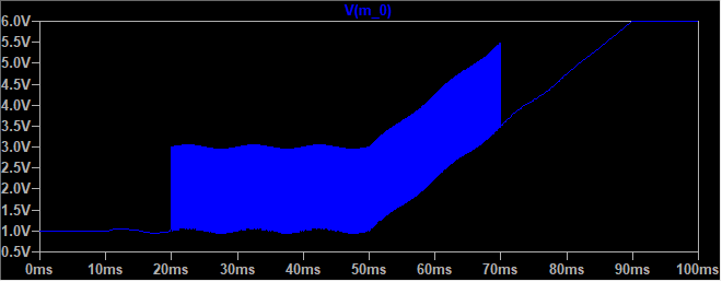
M0 Input:
This first image shows the voltage of the simulated transmitter with distortion from other sources.
![]()
The 50Hz grid distortion begins at 10ms. This is followed by a simulated object in from of the sensor. After 50ms the simulated sunlight comes in.
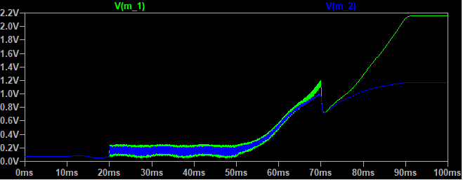
M1 and M2:
The photodiode starts conducting with incoming IR light. This conductance then will create a voltage on the output of the opamp. (Vout = -Iph * Rf)( non-inverting amplifier)
![]()
The photodiode draws a certain current(uA) from the opamp. Because opamps have a very high input resistance, all of the current comes from the output. The amount of current, or in this situation infrared light intensity, will create a voltage. This voltage is then filtered for measurement later in the circuit.
In order not to let the final stage clip too fast, two diodes are placed on the output. The voltage after these two diodes will not be higher than 1.4 Volt.
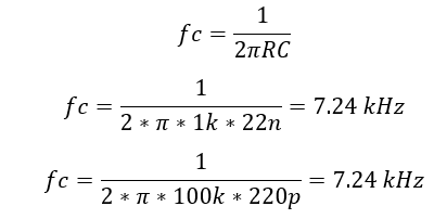
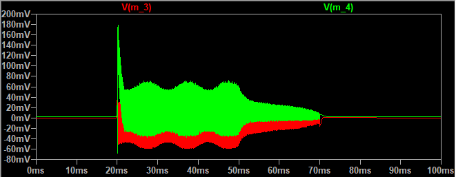
M3 and M4:
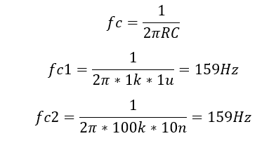
Two high-pass filters are placed after the second stage for filtering sunlight. The filters are connected in series to become a second order RC filter.
![]()
![]()
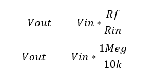
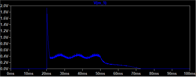
M5:
In this part of the circuit, the filtered signal is amplified in the positive side only. Because there is a diode in the feedback, the opamp will obstruct all negative voltages from the two high-pass filters. This is an inverted amplifier.
![]()
![]()
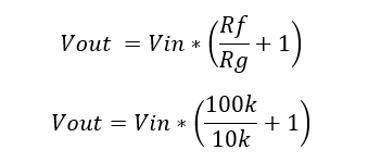
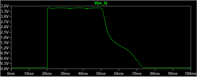
M6:
The voltage measured at the M5 point is quite low. This ensures that the ADC in the Arduino won’t reach his full range. This is why we’ve added an amplifier at the end of the circuit. There’s also a low-pass filter in this amplifier. This filter will flatten the signal so that the analog output fluctuates less.
![]()
![]()
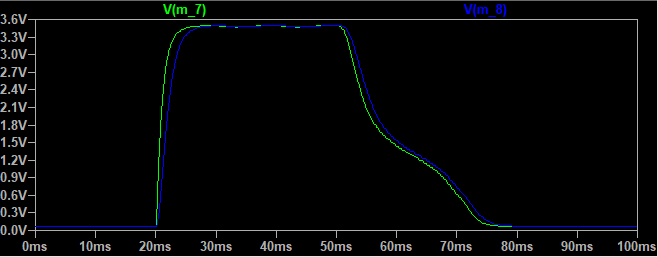
M7 and M8:
Then the signal is filtered even further. In practice the measurement at point M6 still fluctuated too much with the movement of hands playing the Airdrum. Two low-pass filters are placed in series for the filtering of this signal.
![]()
![]()
As the last stage, an opamp is used as a buffer. This is done because there’s one left in the quad configuration of the opamp and it also ensures a stable signal regarding what is used as a load on the output of the sensor panel.
The Airdrum - Make music while moving
Auditive and visual feedback with minimal effort in a modular package for everyone!