 Mike Rigsby
-
1Little Flash 2 Construction
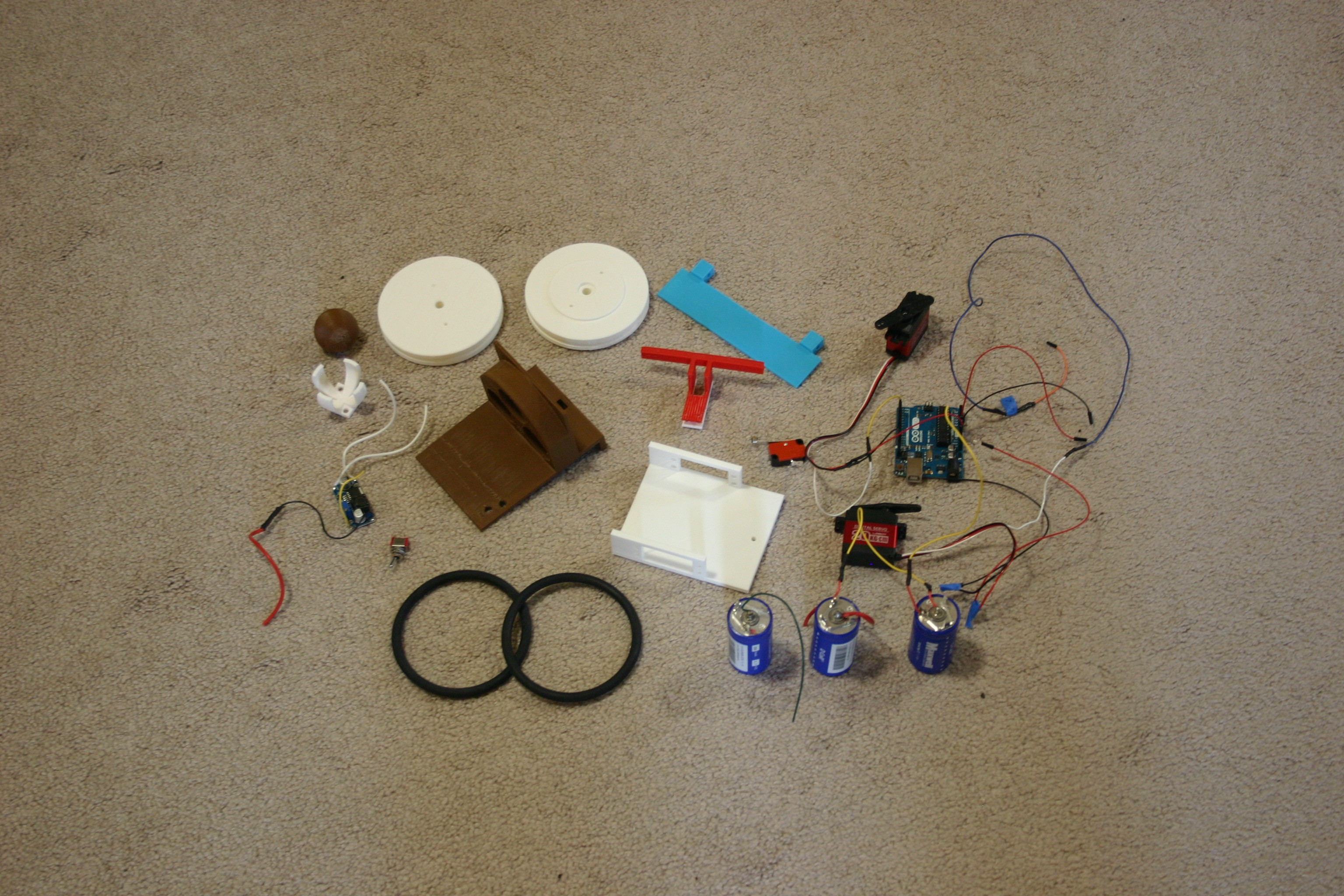
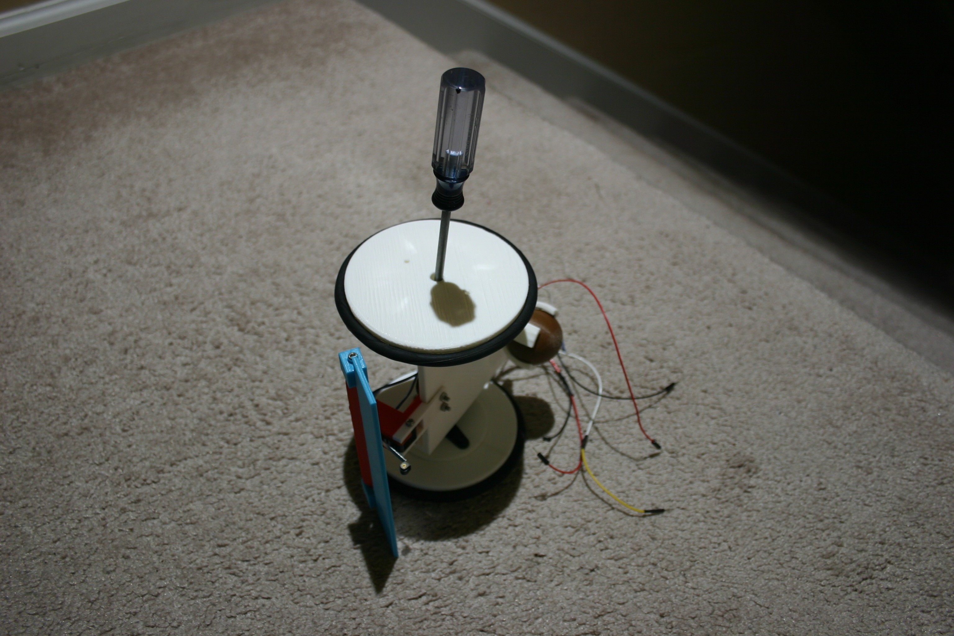
We start with the pieces on the floor.
![]()
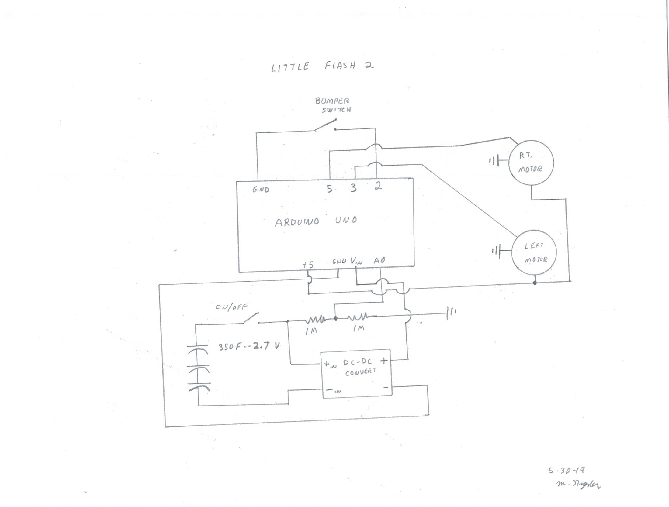
Next, we examine the schematic.
![]()
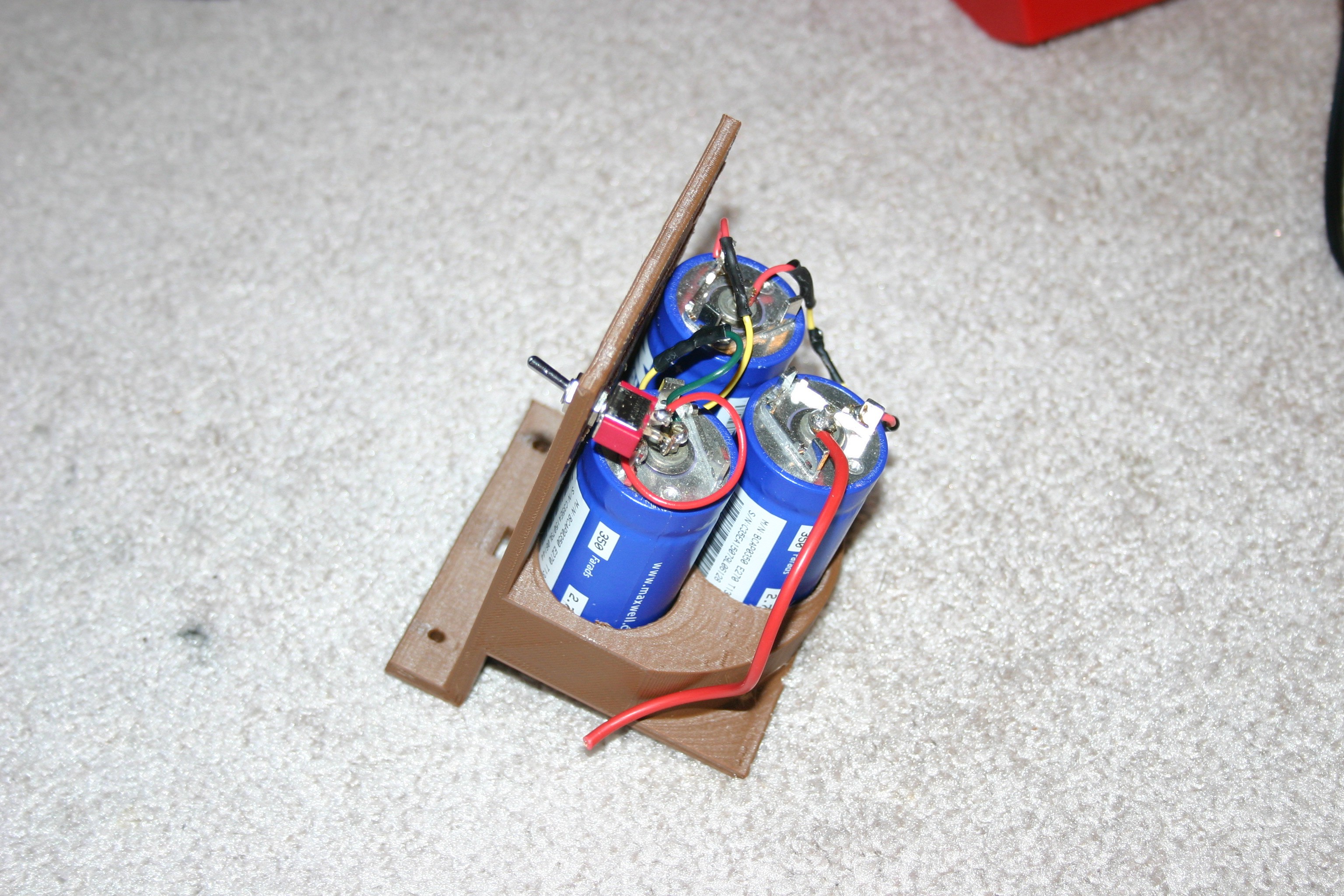
Solder the capacitors and on/off switch together. Place them in the capacitor holder.
![]()
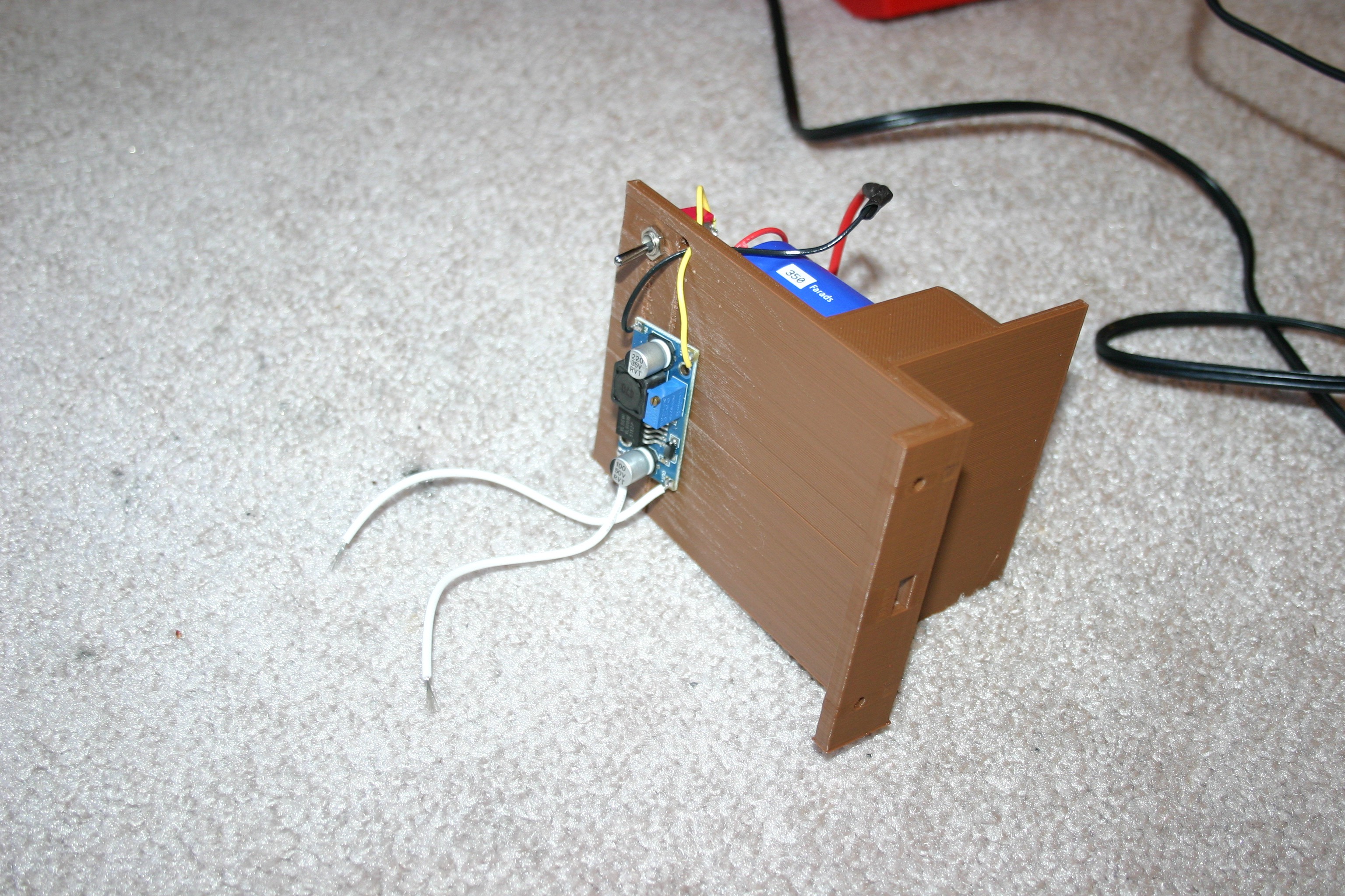
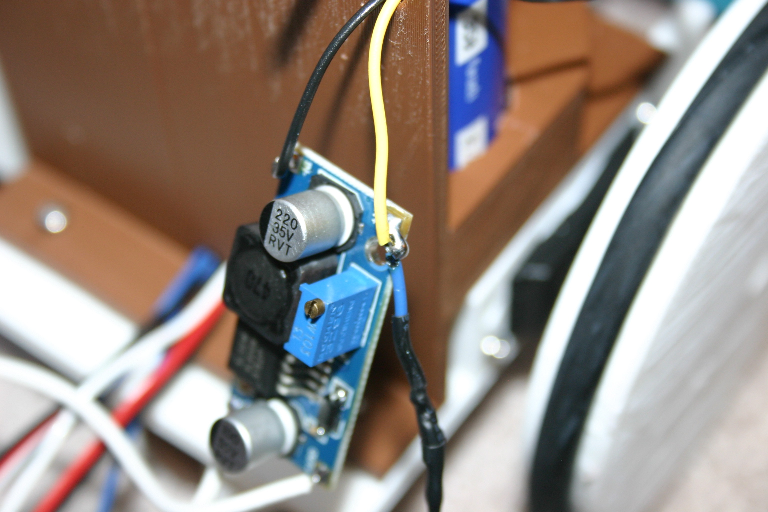
Add the dc to dc converter to the switch side of the capacitor holder.
![]()
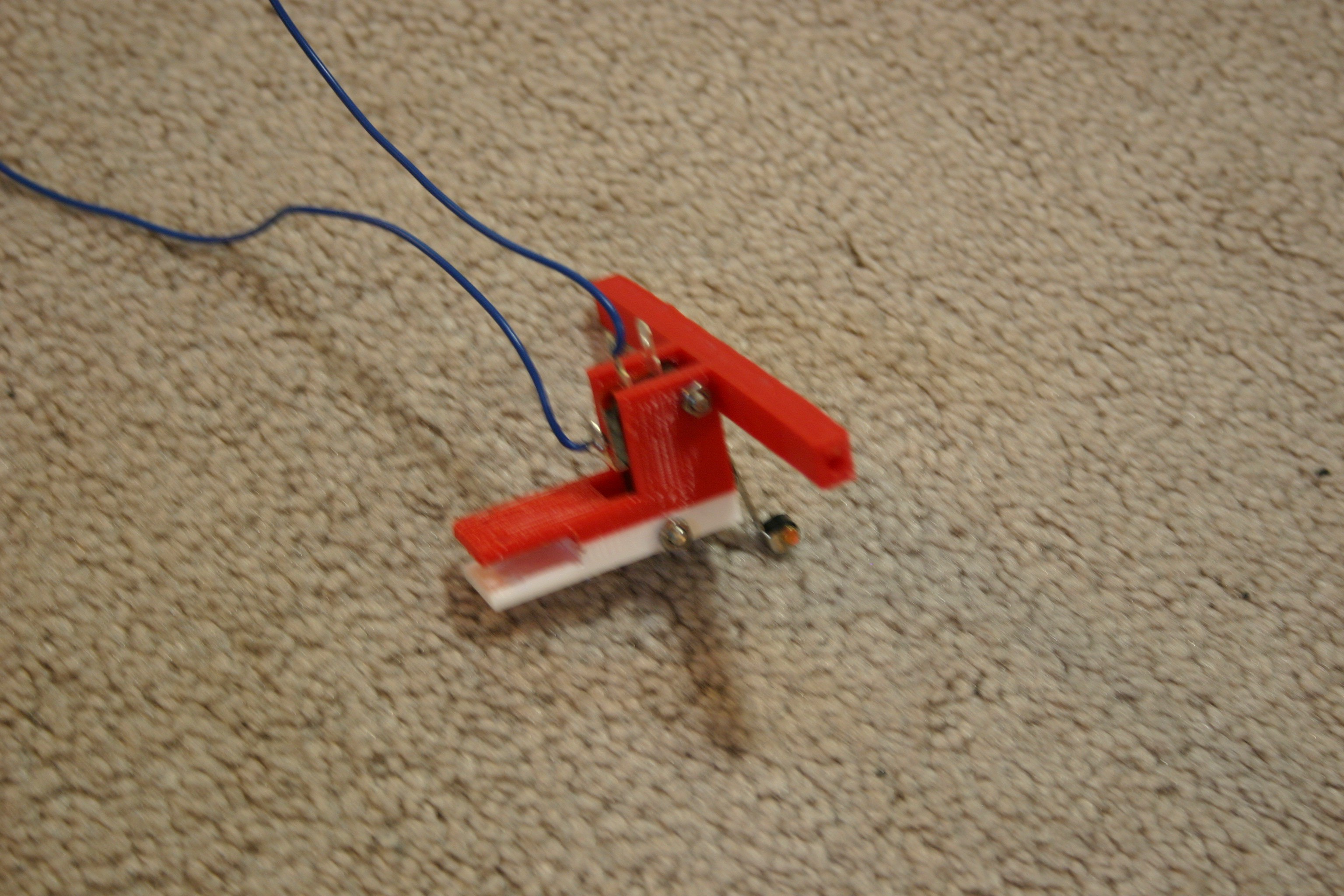
Solder leads to the lever switch.
![]()
Place the lever switch in the bumper bracket using 3mm screws and nuts.
![]()
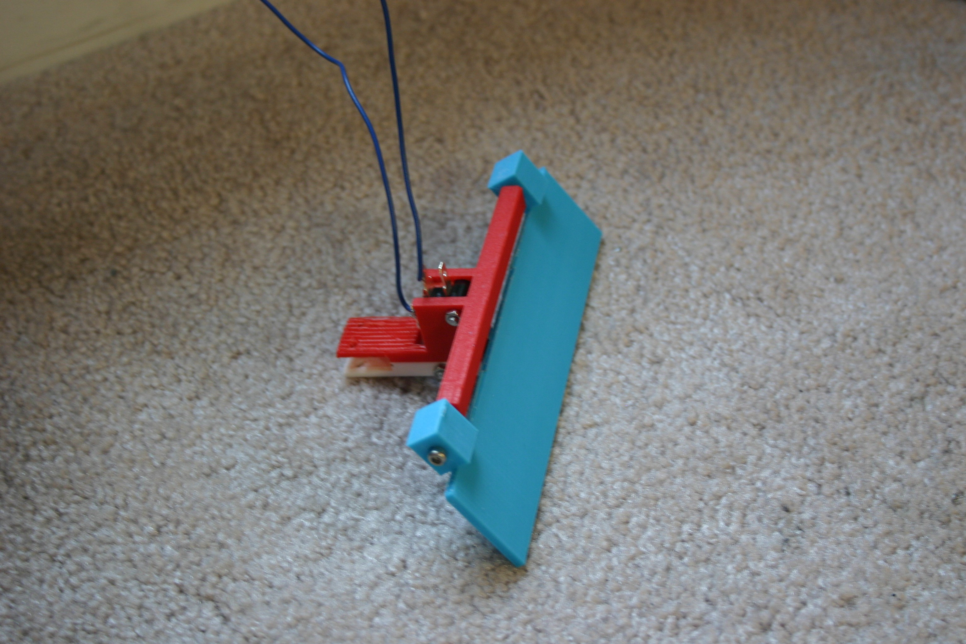
Prepare the bumper to attach to the bracket--it will attach using 3mm screws that thread into the bracket.
![]()
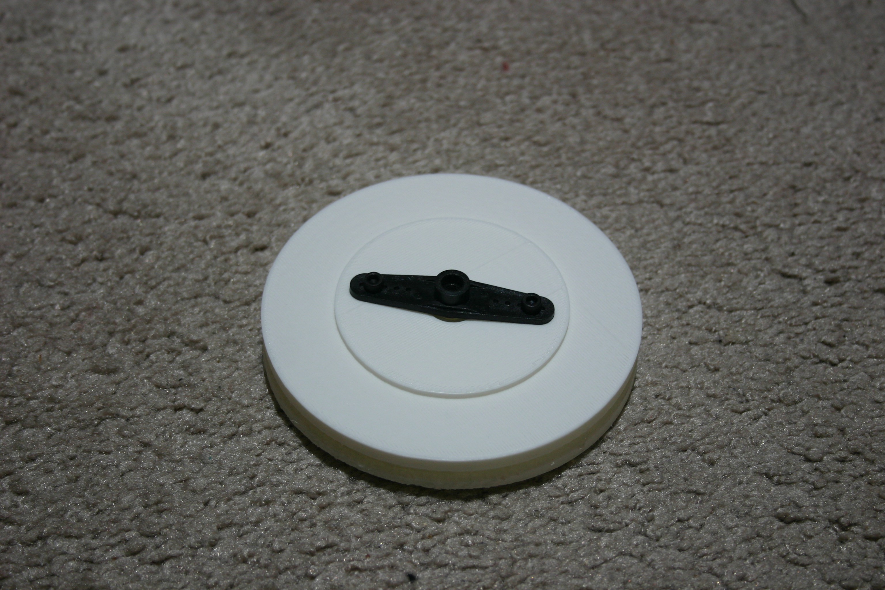
Gather the wheels, servo horns and vacuum belts. Attach the servo horn using 3mm screws.
![]()
Place the "tire" (vacuum belt) on the wheel.
![]()
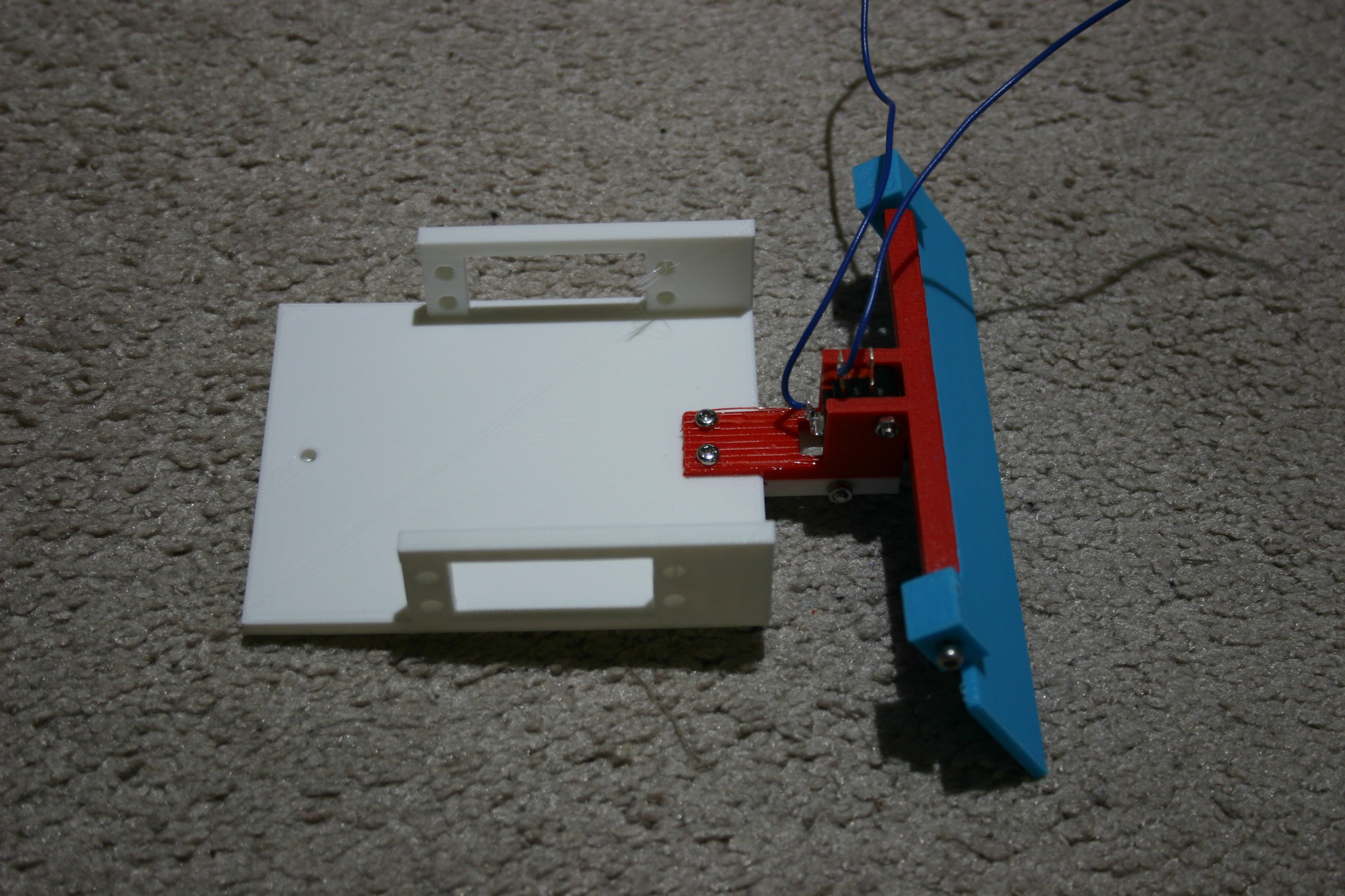
Drill holes and attach the bumper assembly to the frame.
![]()
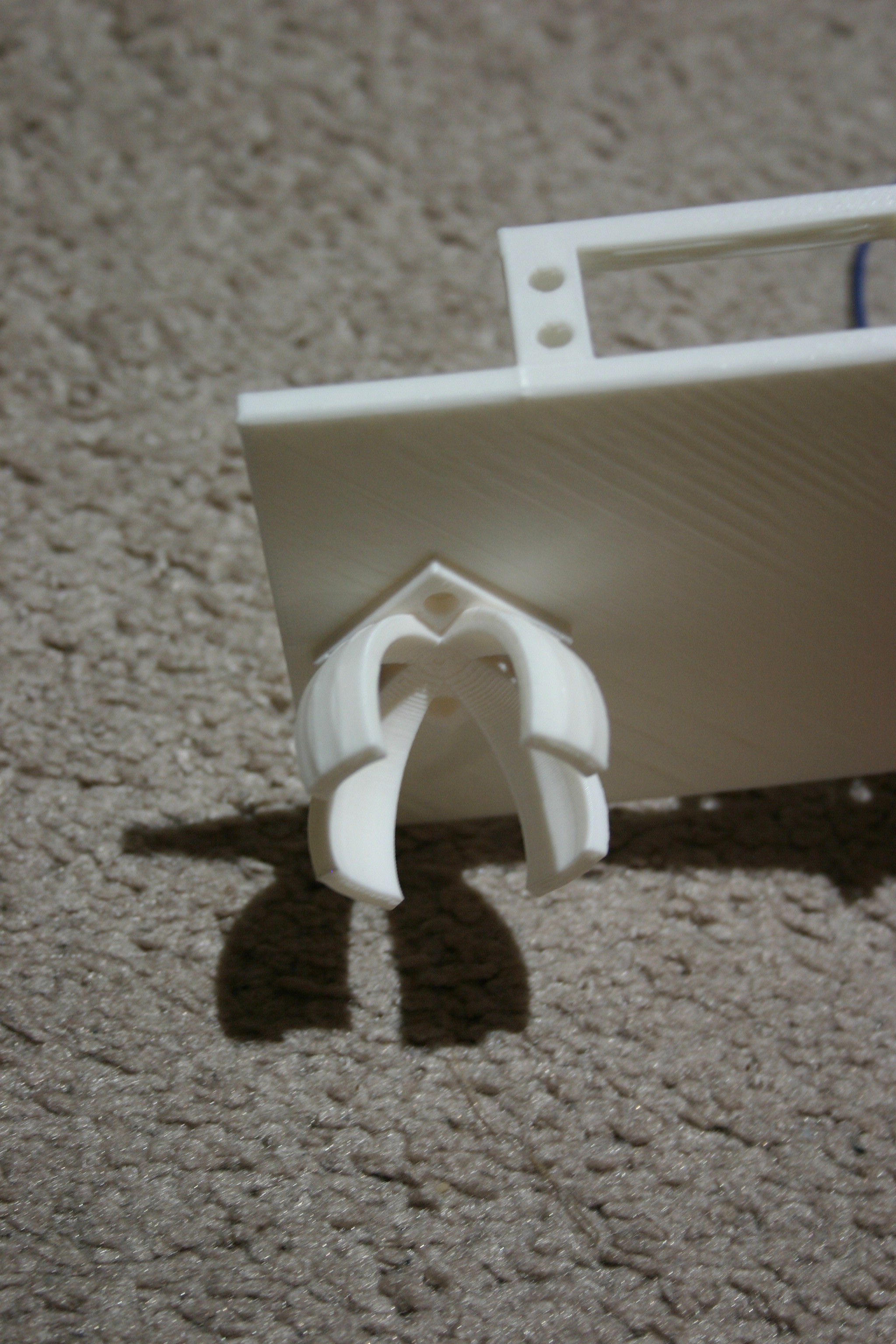
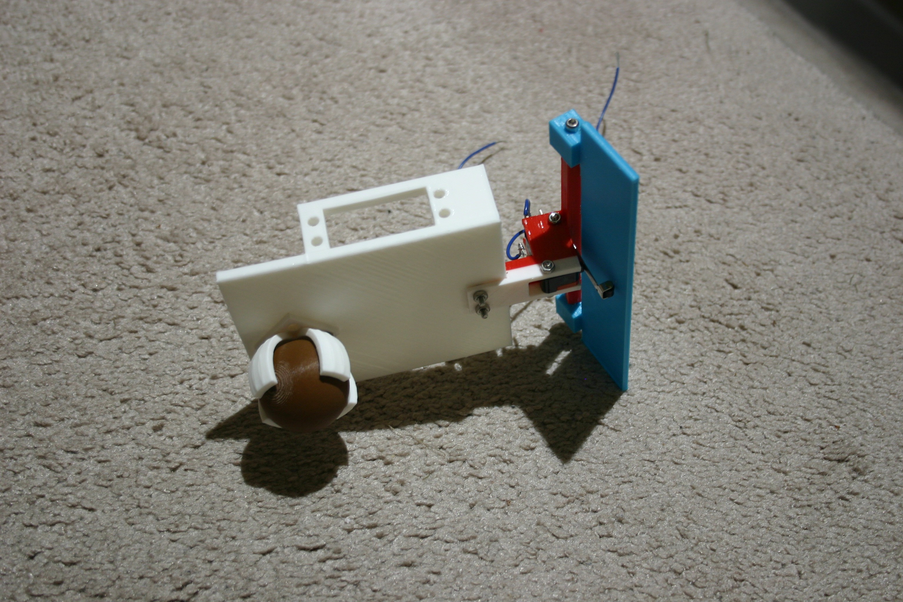
Drill a hole and attach the caster bracket to the rear of the frame.
![]()
Insert the caster ball into the bracket.
![]()
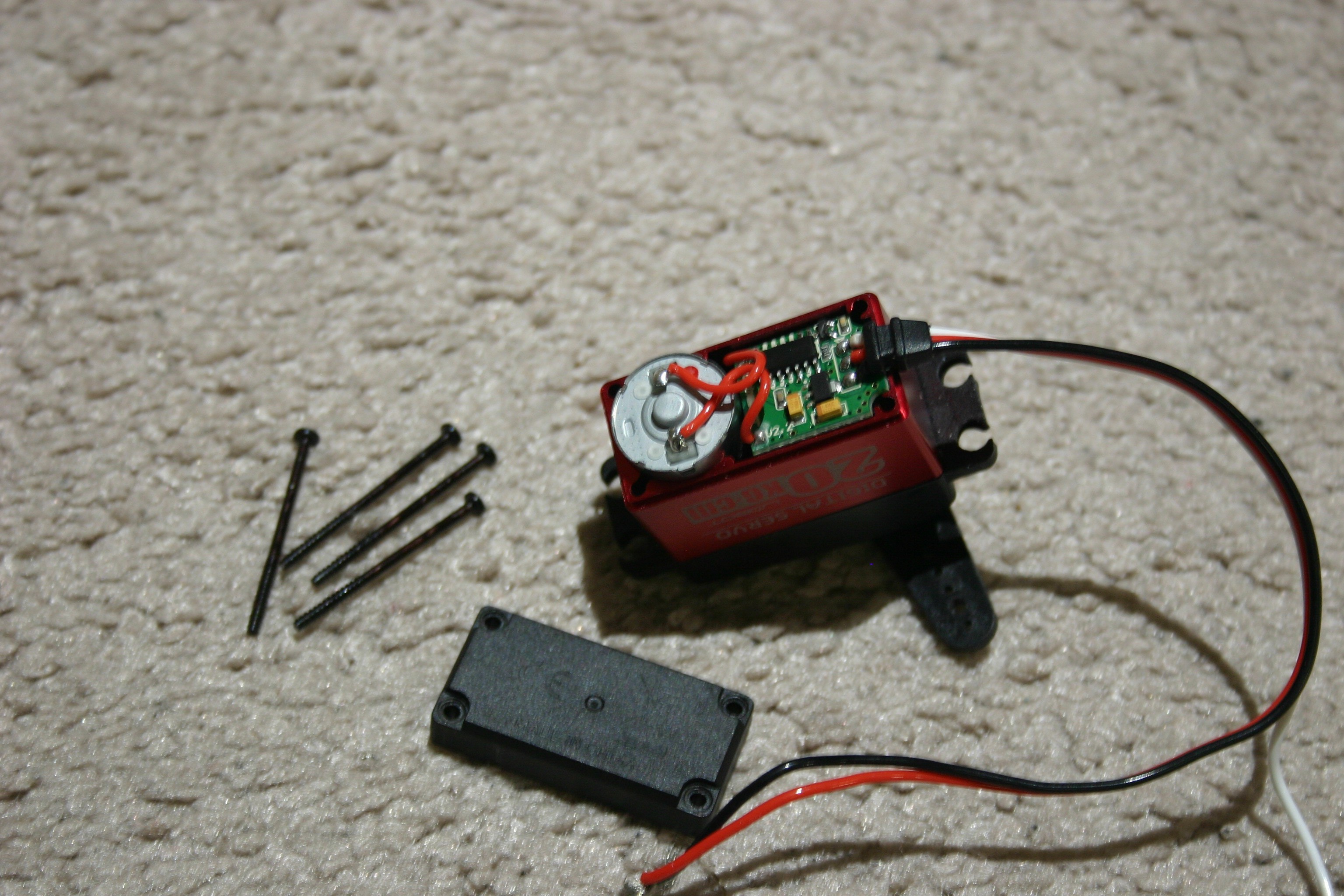
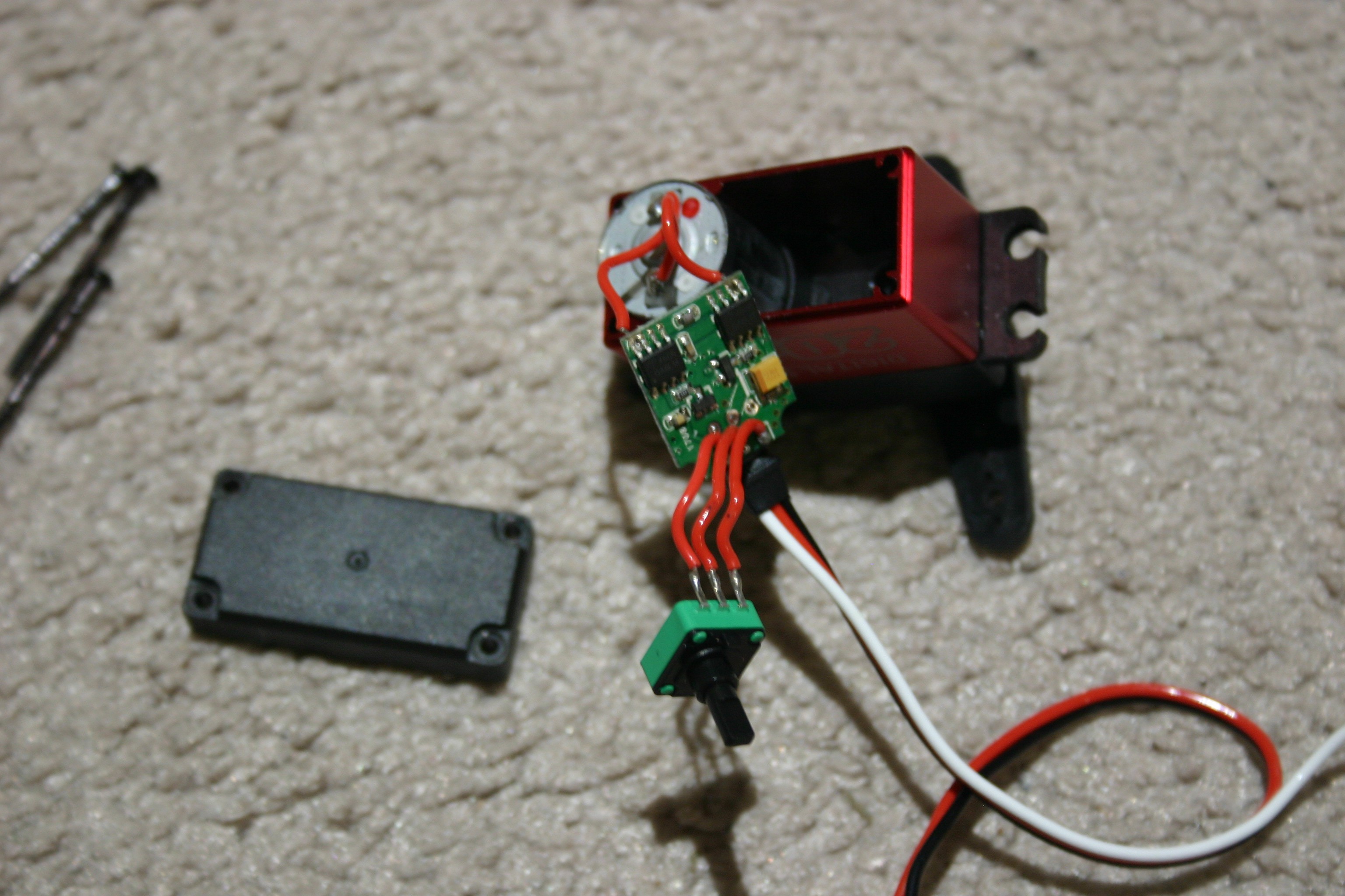
Next, we modify the servo motors. Remove the screws from the backplate.
![]()
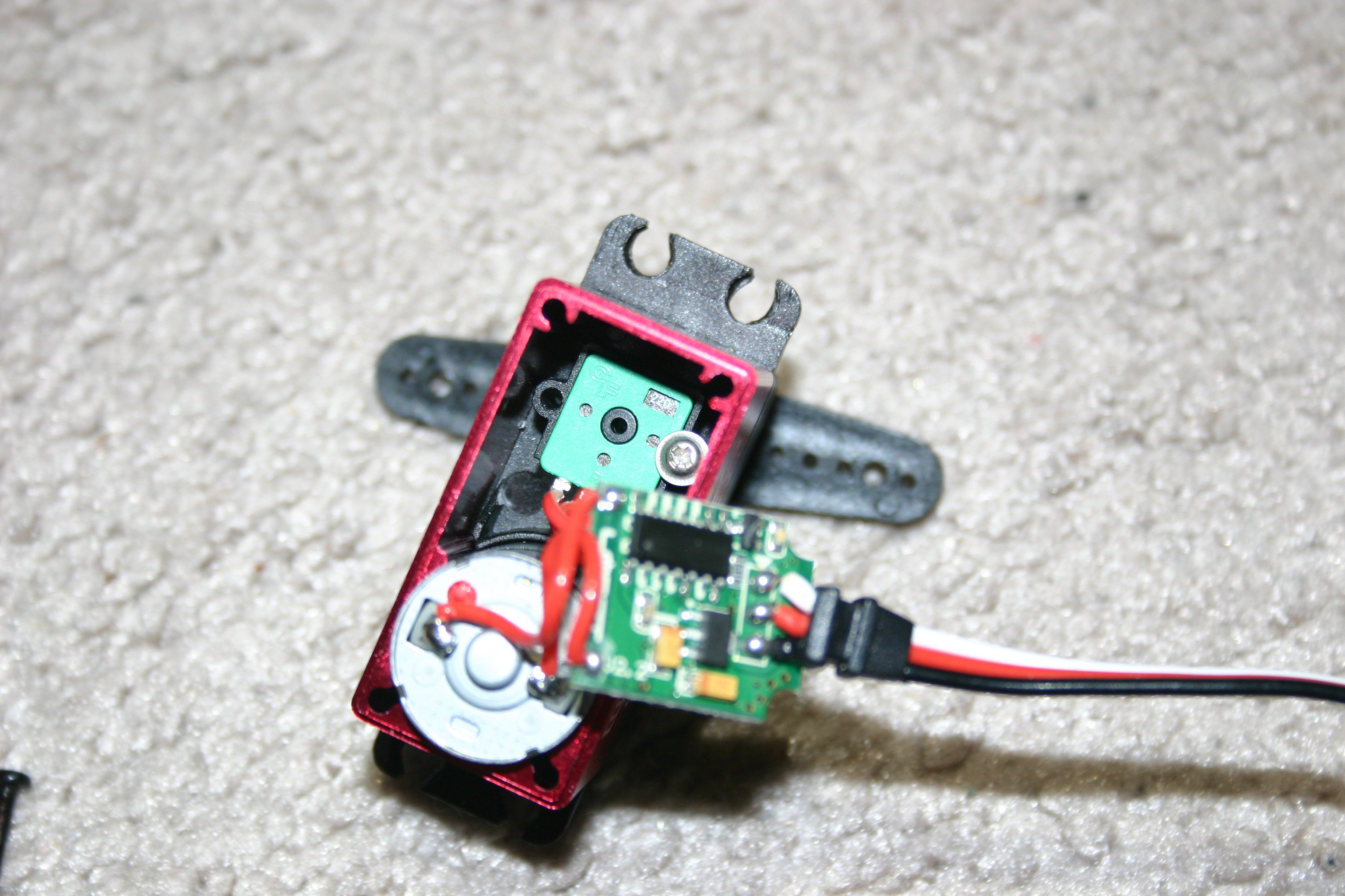
Remove the small "silver" screw (below the circuit board) that holds the pot in place.
![]()
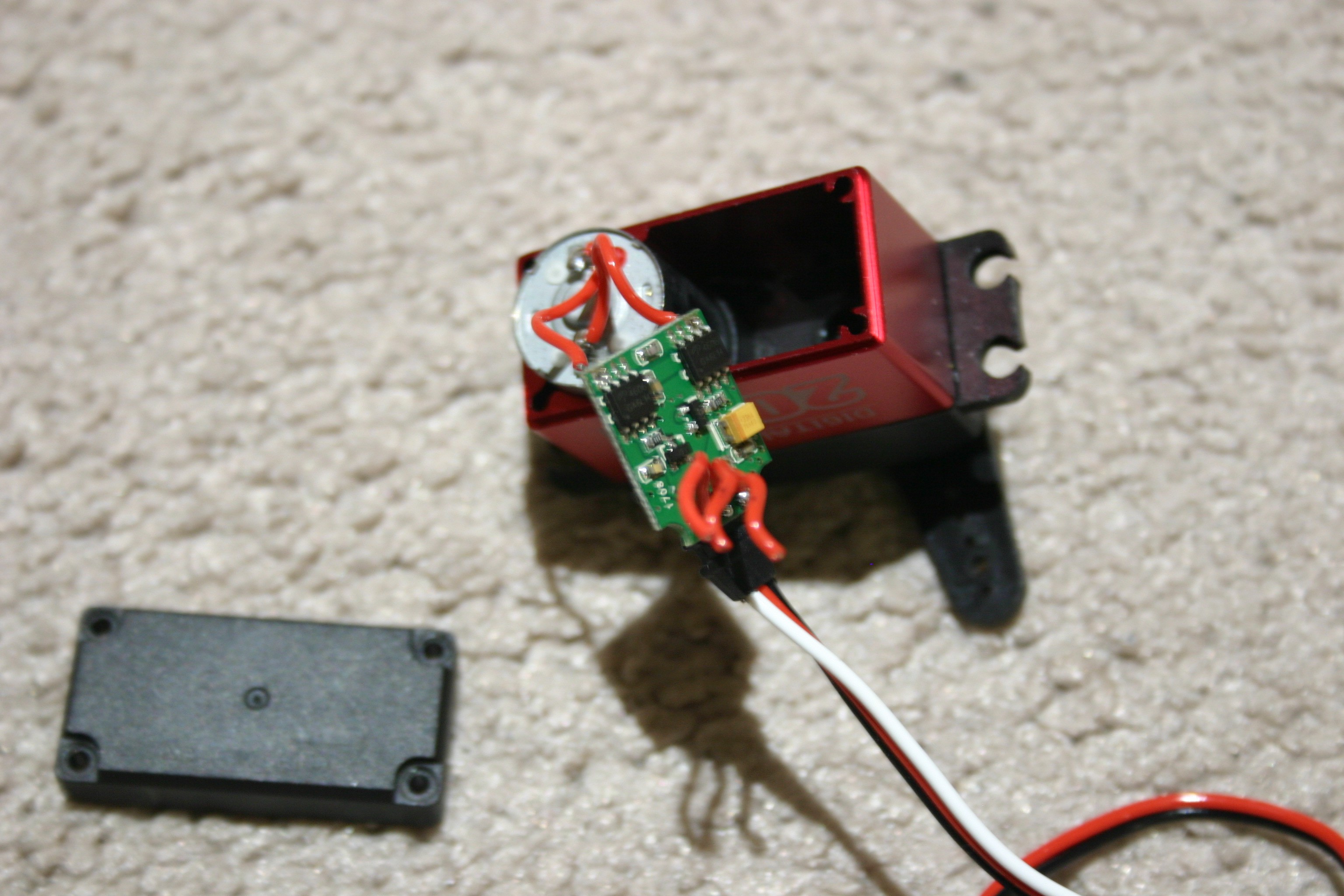
Pull the pot straight out.
![]()
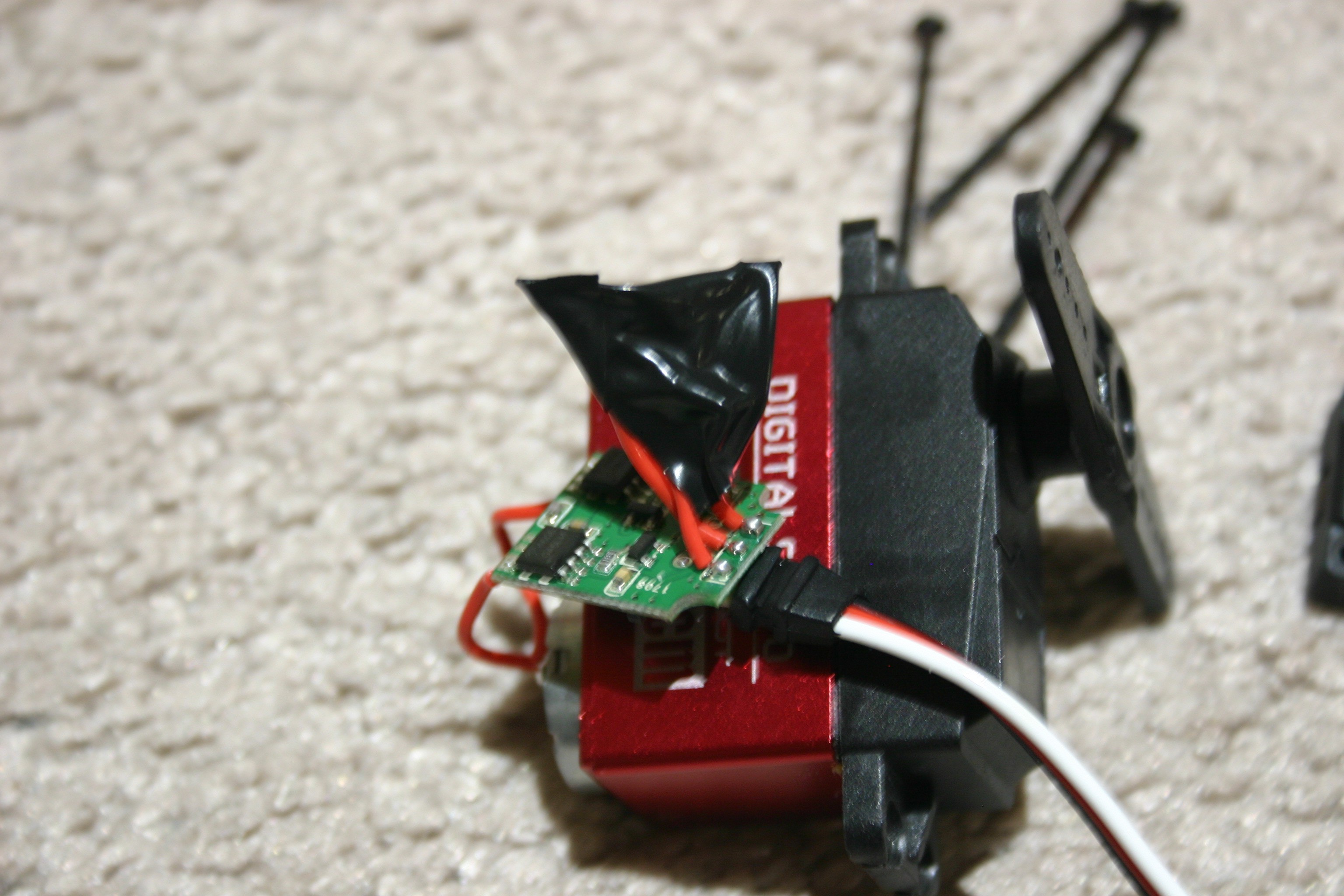
Cut the three wires and remove the pot.
![]()
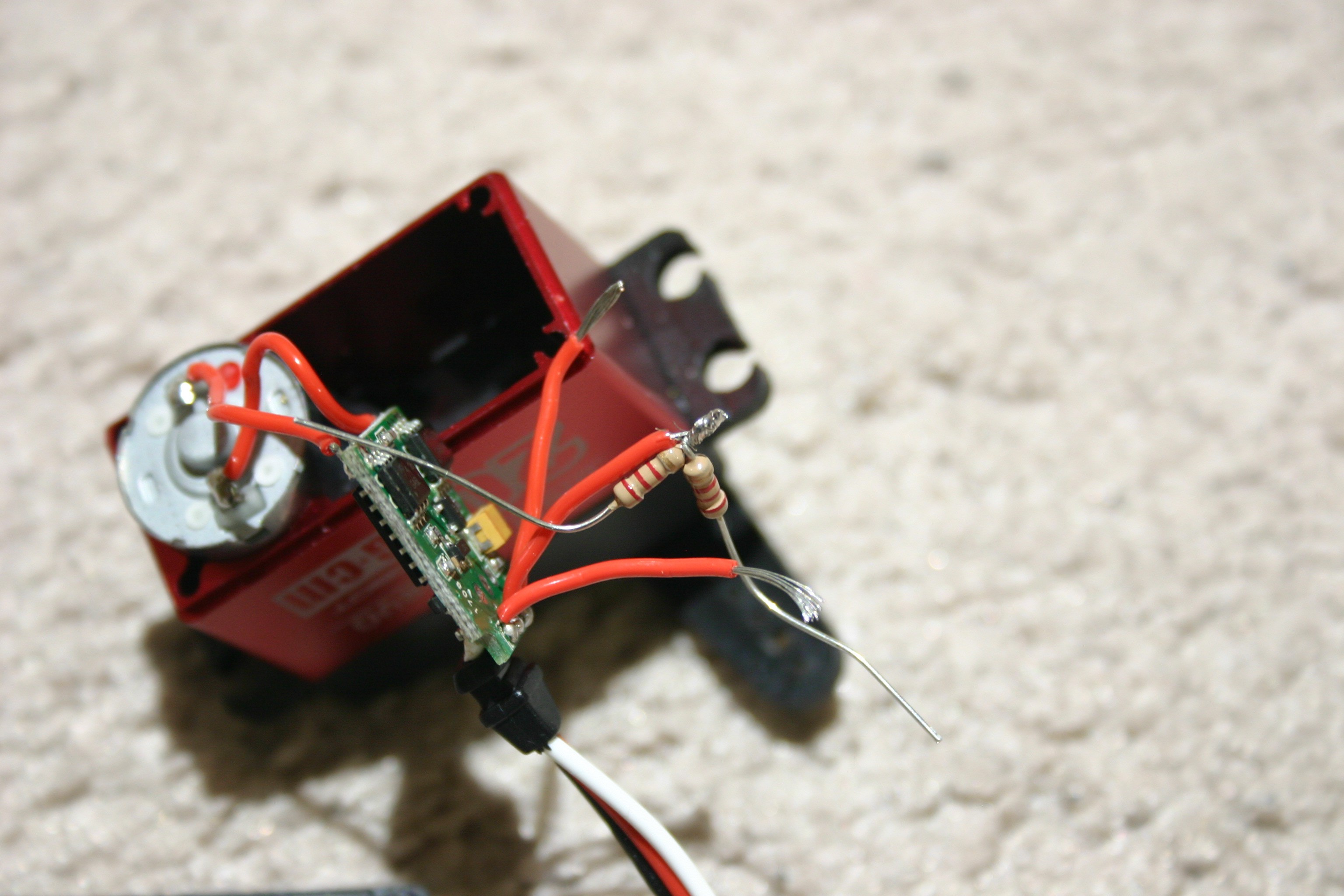
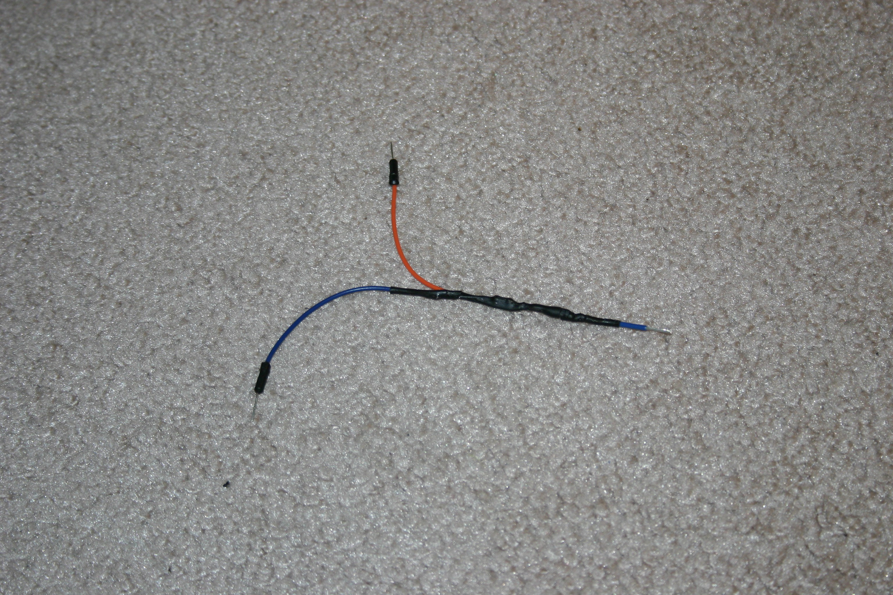
Combine two 2k resistors. Solder the center wire to the connection of the two resistors.
![]()
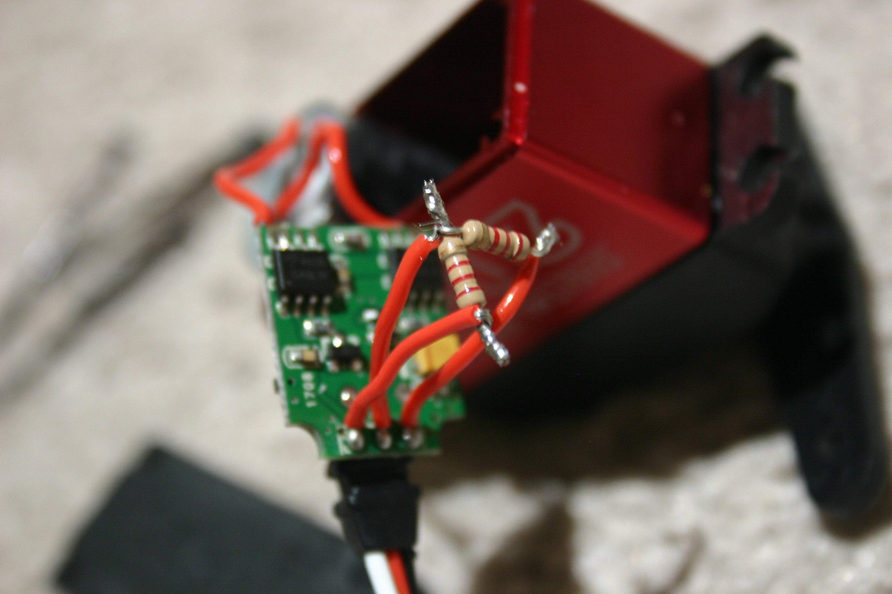
Solder one wire to the end of a resistor and the other wire to the free end of the other resistor.
![]()
Tape the resistor assembly so that the resistor ends cannot make contact with anything else.
![]()
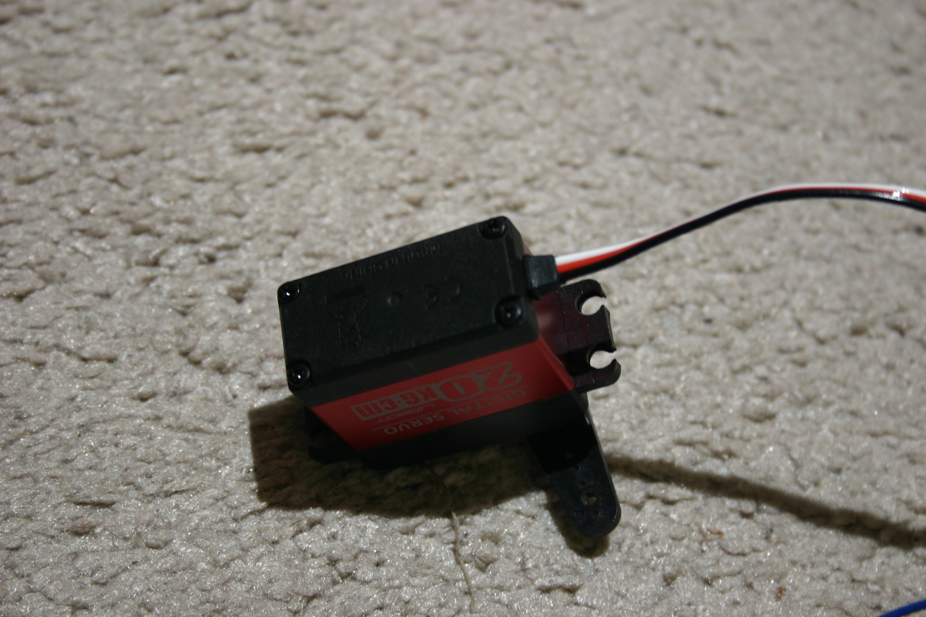
Insert the circuit board and resistors into the motor cavity. Screw the back on.
![]()
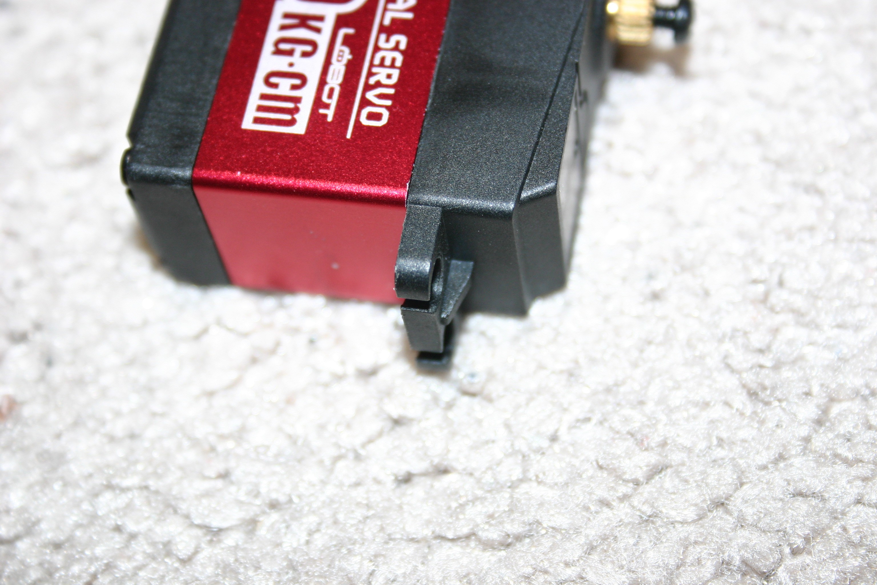
Using a file, remove the plastic nub on the servo mounting bracket.
![]()
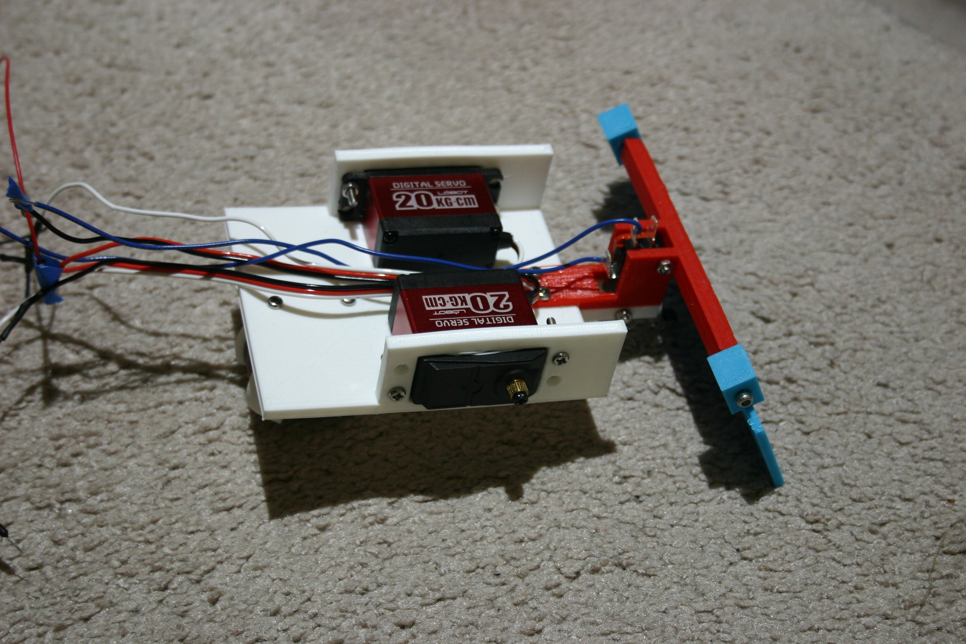
Install the motors in the frame using 3mm screws and nuts.
![]()
Place the wheels on the servo shaft. Secure the wheels using the servo horn screw.
![]()
Route the wires between the motors toward the back of the frame.
![]()
Pull the wires through the hole in the capacitor holder and secure the capacitor holder using 3mm screws (holes will need to be drilled in the frame).
![]()
Solder two 1 Mohm resistors together. Add a wire from the center connecting point and insulate the assembly.
![]()
Solder one end of this assembly to "+ input" on the dc to dc converter. This device is used to monitor supply voltage and trigger the Arduino's onboard led when the supply voltage drops below about 4 volts.
![]()
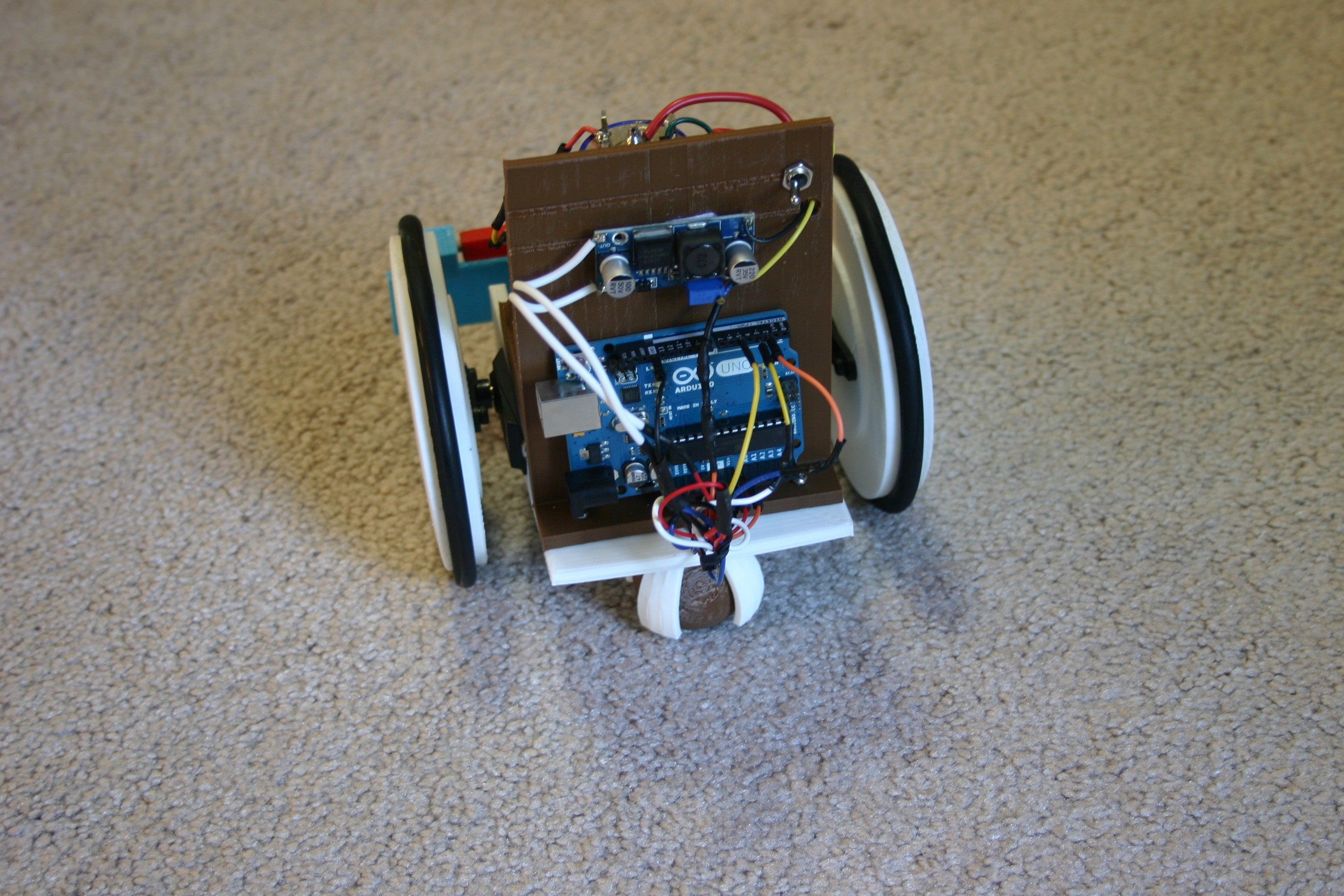
Install the sketch for the Arduino (found in the files), then plug in all the wires according to the schematic and tie wires up for appearance.
![]()
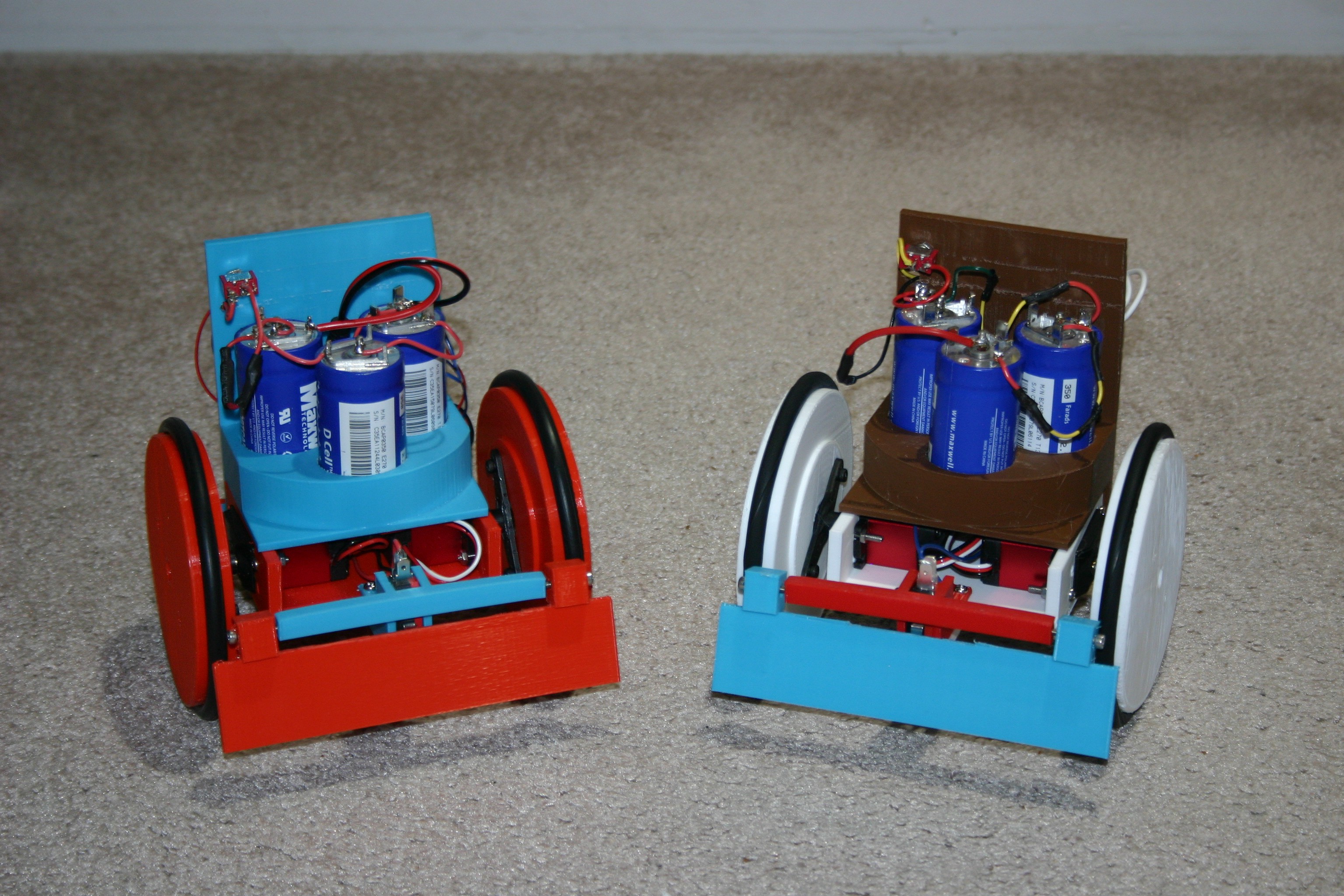
Charge the capacitors, flip the switch and it will run just like Little Flash.
![]()
Little Flash
Little Flash runs for twenty minutes, charges in ten seconds.


Discussions
Become a Hackaday.io Member
Create an account to leave a comment. Already have an account? Log In.