Tyler Gerritsen
-
Mark 2 - Development Update
12/29/2019 at 15:43 • 0 commentsThe new high-speed flash is my pet project, but unfortunately it hasn't been at the top of my priority list recently. Work and family life have used up most of my time, leaving very little for the Mark 2. There have been a few developments recently and I wanted to share!
High-Power Lighting - WOW!
I finally have a working offline driver for the LED's based on the DI AL9910 driver. Three LED's can handle all of the power from a 144W power brick from Amazon, so sharing the load among all 12 LED's will result in a very long lifespan.
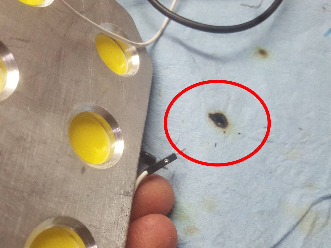
Story time... I had three LED's powered up and was working on the unit. So, I placed the LED's face-down on a shop towel. Within two seconds I began to smell smoke... Turns out the shop towel was catching fire! The LED's weren't even warm at this point, but the power output was enough to ignite paper!
![]() ---------- more ----------
---------- more ----------
Case Manufacturing ToolingThe new case front is going to be made from aluminum for its strength and thermal properties. The cost of manufacturing the case is going to be an issue. I had considered outsourcing the case manufacturing, but for the initial manufacturing run (maybe a dozen units?) I wanted to build the cases in-house to reduce cost. Here's the tooling I came up with to produce the aluminum parts:
![]()
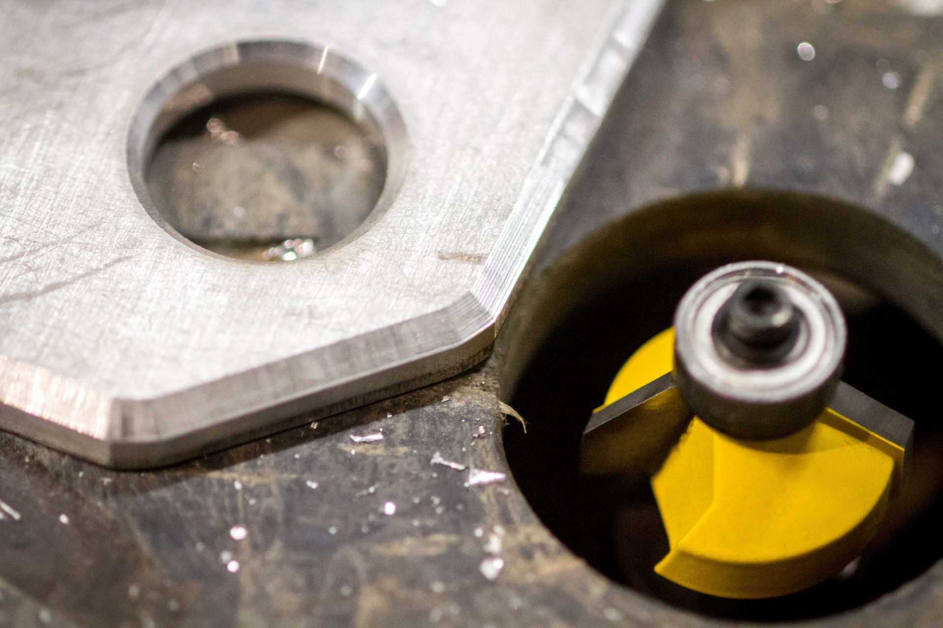
The case will be cut with a table saw, sanded with a belt sander, and the edges chamfered with a carbide router bit ($20 CAD on Amazon). The bit works great!
---------- more ----------![]()
I bought a pricey Keo counter-sink bit for chamfering the LED holes. The surface finish isn't perfect, but I'll try sanding it down later. I'm happy with the result given the price, especially since the chamfered edge isn't designed for reflecting any light.
![]()
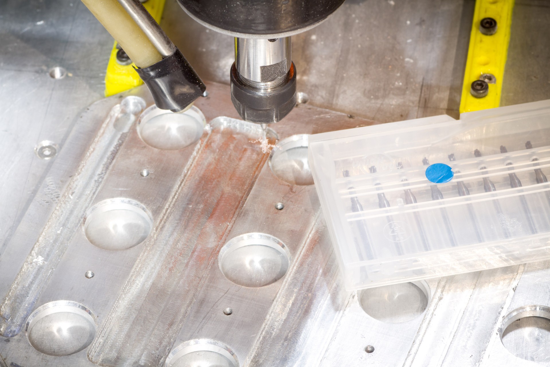
My mini mill is able to cut aluminum at low speed. It will spend several hours to cut out the fine details in the case interior, then I can use a larger mill to hog out the remainder of the material.\
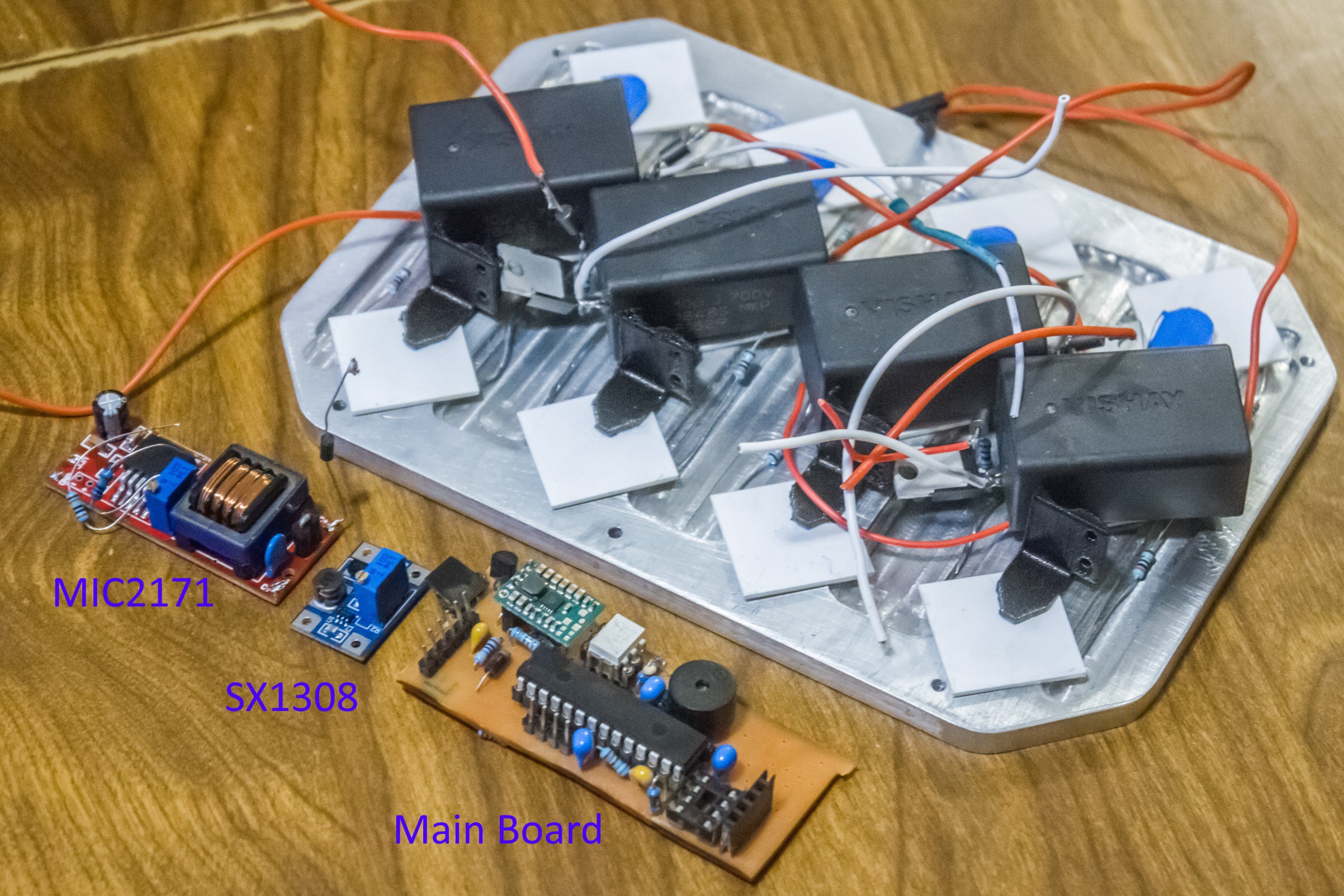
Power Converters - Finished
There are going to be several switching power converters in the new design.
- For the battery-powered modelling light, I'm quite happy with an XL6019 converter purchased from eBay, and will likely source something very similar for the final product.
- Below is a photo of the capacitor charger I designed based on a MIC3172 and flyback transformer, I intend to manufacture these for the final design. I was interested in using the XL6019 output and a voltage multiplier, but the added complexity is not worth it...
- As mentioned, the AL9910-based offline driver works well for the high-power constant illumination.
- I originally hoped to run the control board on 3.3V, but recently changed design to 5V and the board will use a Pololu S7V7F5 Step Up/Down converter to regulate the 4x AA battery output.
- Finally, for the gate drivers, I've been happy with the affordable SX1308 step-up converters which output about 12V.
![]()
-
Mark 2 - Development Update
11/02/2019 at 02:08 • 0 commentsDevelopment is continuing! Here are a few blurbs about recent design work.
Control Board Design 95% Complete
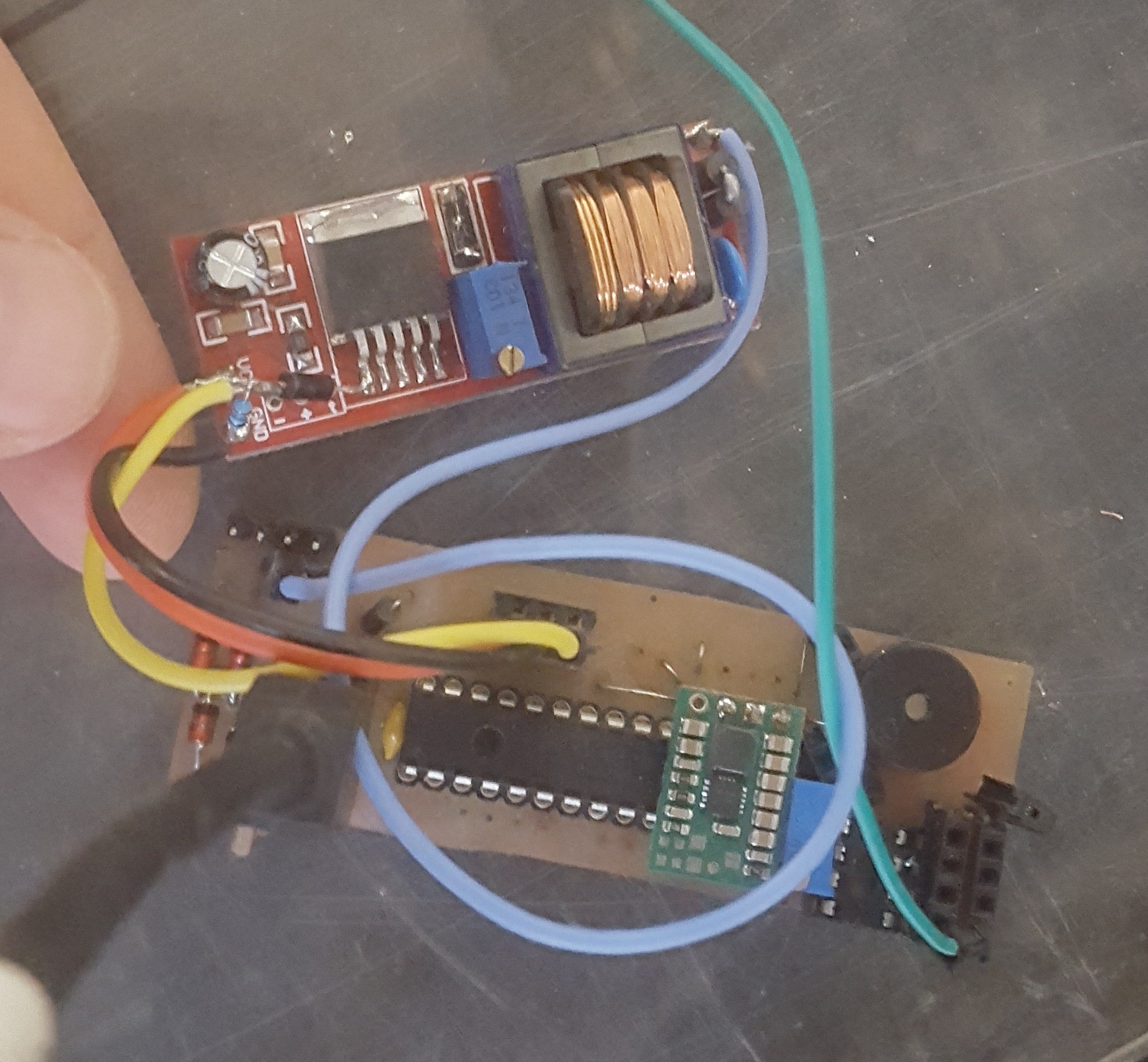
The main control board design has been generally completed. A few minor tweaks need to be implemented (primarily related to the high-power DC converter, which hasn't been designed yet). Some testing has been performed with the prototype board and the MIC2171 flyback converter I found on eBay
![]() ---------- more ----------
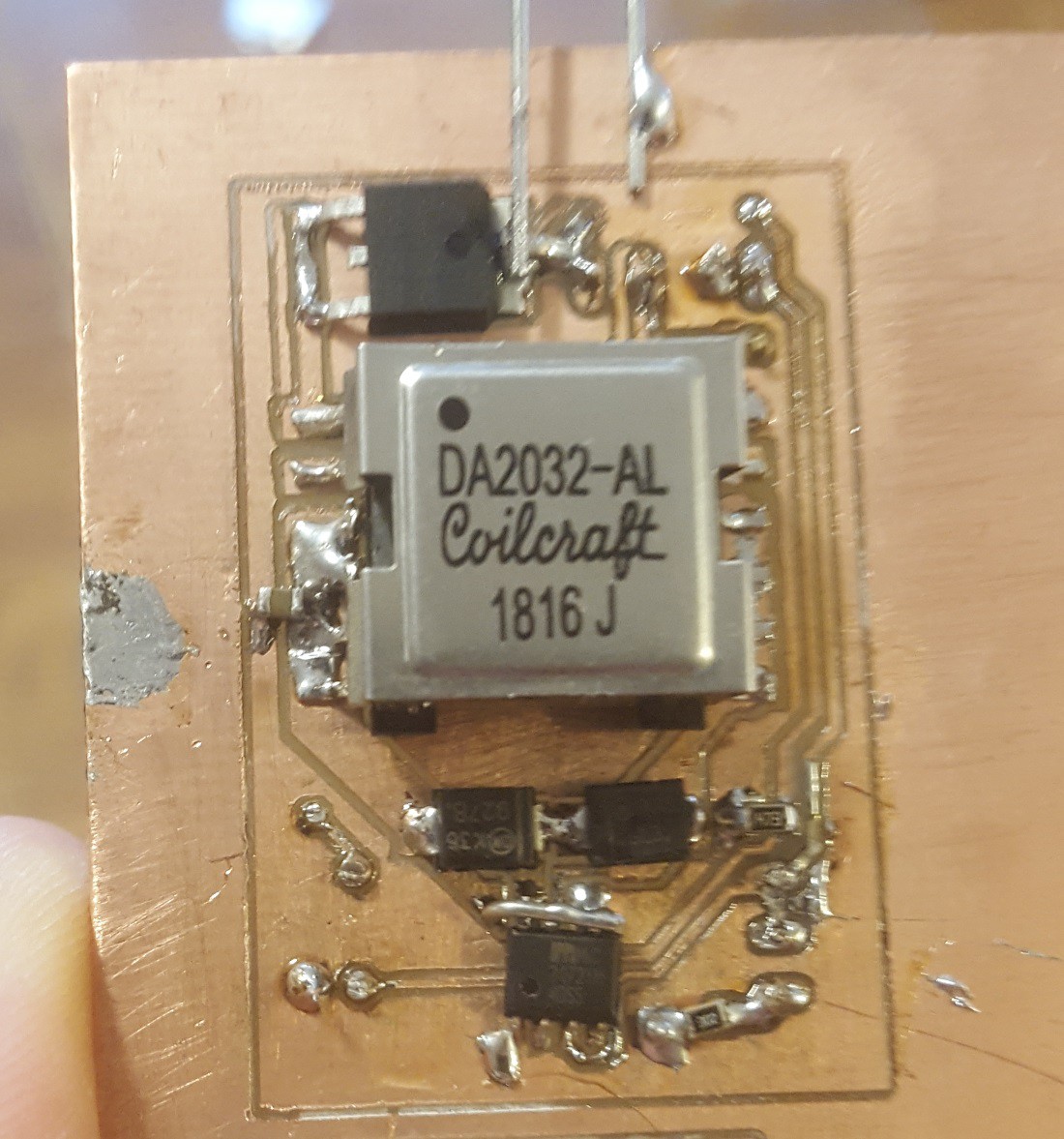
---------- more ----------High-Voltage Boost Converter
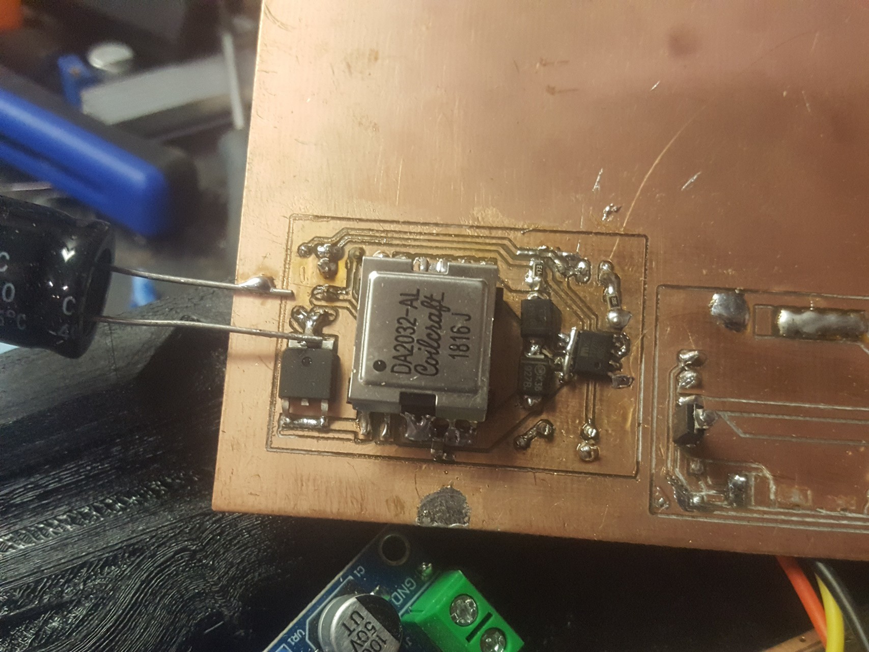
The MIC2171 has been working great for charging the capacitors, but there are a few problems. The transformer was optimized for higher voltages, and the converter control isn't ideal. I found the MIC3172 is very similar, but has an ENABLE pin. I designed a converter based on the MIC3172 and a Coilcraft DA2032-AL transformer, which is ideal for 120-volt output. The entire package is a little less expensive than the eBay converter, but unfortunately adds some work for manufacturing.
![]()
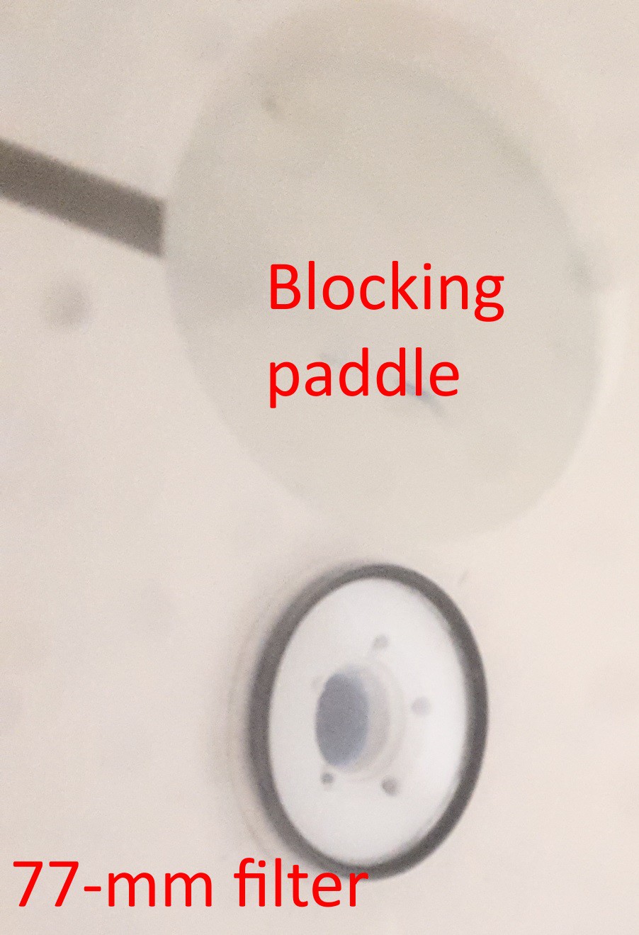
Active Light Probe & Integrating Sphere
I need to plug NQTRONIX and his active light probe. It has been perfect for taking direct measurements of the light output with the new control board. A paper mache'd exercise ball makes a reasonably good integrating sphere. The light output on a bank of three LED's is a bit too bright for the light probe, so more recently I added a mount for a 77mm ND filter. I have a 6-stop and a 10-stop filter, so eventually I can measure the output of the entire flash.
![]()
Test Data Available On Github
I'm making an effort to upload all of my test data for Edgerton and the Mark 2 to github (https://github.com/td0g/high_speed_flash/tree/master/R%26D). This can hopefully be useful for anyone else interested in working with high-speed LED pulses.
-
Control Board 1.2 Released
09/29/2019 at 03:25 • 0 commentsWhat's changed?
Simplified External Trigger Protection - A single 1N4001 diode and two resistors protect the microcontroller from most causes of damage. This protection circuit is cheaper and simpler than the V1.1 circuit, but much better than the V1.0 circuit.
- Solid-State Relay (SSR) Boost Control - Instead of the complex circuitry introduced in the V1.1 design, a single component is used to turn the high-voltage boost converter on and off. The voltage drop on the load side is about 200 mV when driving the boost regulator, while it only uses less than 50 mA to run. This is much better than earlier control circuits. A number of SSR's will work, but I recommend the Vishay VO14642AT ($3.81 CAD on Digikey).
- Single Control Board - With the SSR mounted on the main control board, there is no need for a second control board for the boost converter. This simplifies both construction and the wire routing inside the case.
- Pre-Built Control Boards Available For Purchase (SOON) - I've prototyped a control board and will have a small number manufactured soon for those who are interested in building a flash. I hope to keep the price low with a slim profit margin to support my continuing experimentation with the LED's.
What else is going on?
Development of the Mark 2 is ongoing. The control board has gone through several iterations, a handful of LED's have been destroyed with the powerful new circuitry, and I only wish that I had more time to devote to its development :)
I'm also working on organizing an overview of my experiments for those who are interested in all the details. The setup and results will be shared, likely on my website (www.td0g.ca).
NQTRONIX has sent an active light probe which arrived a few weeks ago. Sadly I haven't had time to experiment much with it, but hopefully soon I can begin collecting data to answer a number of questions. I've built a crude integrating sphere to use with the probe. Here's a teaser from the fooling around I've done so far: The LED's appear to turn on REALLY REALLY fast and turn ALMOST off JUST AS FAST. My claims of sub-microsecond pulsing will soon be proven with some oscilloscope traces!
-
Mark 2 - Development Update
08/13/2019 at 03:34 • 0 commentsIt's been some time since I posted about the continuing development of the Mark 2. Progress has slowed recently as I've been distracted by a back injury, meanwhile my work and family have taken some priority over the project. Here's a summary of the Mark 2 progress thus far:
Electronics
The LED circuits have not changed at all. The control board, however, has undergone a complete redesign. One of the main goals was the ability to run on 4x AA batteries (3.2 - 6.0 Volts). Realization requires three switching power converters (I purchased complete converter boards in order to save development time):
- 3.3v converter for the control board (Pololu S7V8F3)
- 15v converter for the gate driver (SX1308 Boost, purchased from eBay)
- 125v capacitor charger (MIC2171 Flyback, purchased from eBay)
---------- more ----------This many converters may seem like overkill, but having three separate power supplies has benefits. First off, the microcontroller's supply is completely separated from the gate driver (no fluctuations from the gate driver can affect the microcontroller, unlike that one time it happened and I ruined all the LED's). Second, maintaining 15v for the gate driver means the transistors will perform the same regardless of battery voltage level. Finally, each converter is tailored to serve its function. The power consumption has been significantly reduced compared to the Classic model.
Case Design
The mantra during development of the Classic design was to make it easy to produce a working unit. For the Mark 2, I'm focusing on improving the market value of the unit. The case is partially constructed of metal. The front of the case is made of 1/4" 6061 Aluminum, which will give the unit much better structural and thermal properties. The back portion will still be 3D printed, but I intend to use ABS and post-process it with a vapour bath. The size of the unit has been decreased in every dimension, thanks to smaller electronic components and fewer batteries.
![]()
The rear half is being printed as I type. The front half was fabricated using a 3D printed template for the holes and valleys. If I build any more units, the front halves will likely be CNC machined.
So, why am I giving any consideration to the case's thermal properties? Because of the plan to include...
Constant Light Mode
Edgerton has easily 150W of LED lighting power, and it's a bit of a shame that the Classic does not have any way to turn them on for constant lighting. There are two reasons that constant lighting would be helpful: modelling light (which gives a preview of how the lighting is set up and lets the user test different lighting angles in real-time) and image/video lighting.
Because of the huge amounts of lighting power available and the limitations of AA batteries, I'm still contemplating how to design the power supply system. An external supply is definitely needed to produce more than a few watts of power, and I may develop an external pack which can be plugged in to mains power. Providing 150W of power will allow for high shutter speeds, but will only be usable for a few seconds at a time due to the heat generated. 20W - 50W will probably be more sustainable for longer periods of time.
A set of fully-charged batteries could probably supply 10W of power, which can easily be converted to the LED's forward voltage. This may be enough to serve as a modelling light, so that the user doesn't need to plug in an external power supply just to setup the flash.
Unfortunately each of these components is going to add cost and complexity to the unit. Edgerton's primary purpose is high-speed flash photography, and I don't plan to compromise that ability just to add continuous lighting. It's likely that I can add the battery-powered continuous lighting function without much cost, but the mains-powered function may or may not make it into the final design.
-
Tripwire Trigger System Functional
07/01/2019 at 13:22 • 0 commentsVarious methods of triggering are available for high-speed photography, but the triggering systems are not cheap. In an effort to make the hobby accessible and affordable, I've added a built-in triggering system that doesn't require any major hardware. The 'Tripwire Triggering System' works by placing a special jig on the muzzle of the rifle. A fine wire is positioned in front of the barrel, and when the projectile breaks the wire, Edgerton will strobe after a pre-programmed delay.
![]()
Here's a photo with the triggering system set to 0 delay (triggering as soon as the tripwire is broken). You can see the tripwire breaking just left of the projectile.
---------- more ----------Part of the challenge was to add the functionality without affecting the intuitive user display. The limitations of the 7-segment display really become apparent here. The delay setting can be selected by pressing the encoder button, then turning the encoder to adjust the delay. At delays shorter than 90 milliseconds, the display shows the delay in the format XX.XX milliseconds - although the decimal point is actually a colon. I wish that the points on this cheap display could be controlled independently so that it could show an actual decimal point. At 90 milliseconds and above, the display shows the delay in the format XXXX milliseconds (no decimal point).
This triggering system requires that the user knows the projectile's speed beforehand. Without knowing the speed, the projectile's position after a given delay isn't known. It is possible to calculate the projectile's speed by taking a photo of a free-flying projectile after a given delay and determining how far it traveled from the muzzle.
Very fine wire (such as the strands in 22-guage silicone wire) is required. As shown below, the wire can affect the bullet's trajectory.
![]()
-
Edgerton V1.1 Released
06/09/2019 at 15:14 • 0 commentsWhat's New?
The design for Edgerton has been updated to address several issues in the original design. The circuit diagram, bill of materials, and 3D print files have been updated. A new complete assembly manual has been written and made available. The overall cost has increases slightly (less than $5) because of some new components. Assembly requires a few more steps, but they are simple and the benefits greatly outweigh the cost and added assembly time. Below is a brief overview of the changes and their rationale.
Reduced Power Consumption
The microcontroller's isolation from the high-voltage boost converter is important to prevent resetting, and this was originally accomplished using a relay board purchased from eBay. Unfortunately the relay drew several hundred milliamps, about as much as the boost regulator.
The relay has been replaced with a P-channel MOSFET, opto-isolator, and a couple resistors. The new circuit draws about 30 mA - and may be reduced further with some optimization. Isolation is maintained via the opto-isolator. The cost has not increased and the circuit is easy to assembly and install. A small benefit is the removal of the relay mount in the case, which means a reduction in filament usage.
Ferrite Beads for the Gates
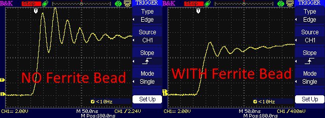
I previously noticed some significant ringing in the MOSFET gates. Thanks to advice from a friendly German named Volker and guidelines presented in this application note from ON Semiconductor, I ordered some ferrite beads and installed them at the MOSFET gate leads. Here's the gate signals before and after the ferrite beads were installed.
![]()
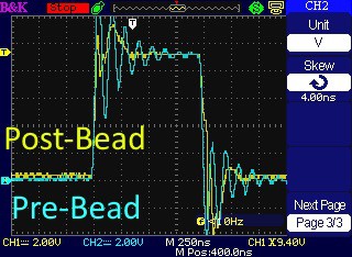
The gate signal is cleaner. Here's a trace showing how much the ferrite bead cleans up the signal.
![]() ---------- more ----------
---------- more ----------LED Series Resistors
Typically LED's are never connected directly to a power source. Series resistors or drivers are used to regulate power consumption. The original design for Edgerton did not include any components to limit current to the LED to maximize efficiency. Unfortunately the LED voltage showed a concerning amount of ringing during switch-on and switch-off.
The 1.1 revision now includes 2-ohm series resistors on the LED anodes. Metal film resistors were selected to minimize inductance. Although the resistors dissipate far more than the 1/4 W they are rated for (it's actually more than 300 watts), the power lasts for such a short amount of time that it's not problematic.
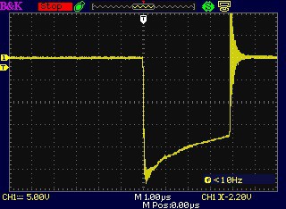
Below is a trace of the voltage across the resistor with a 95V driver voltage. NOTE that this was tested after the ferrite beads were installed. The turn-on current is very smooth, but there's still ringing during turn-off. That's may be due to inductance in the circuit. The decrease in current is interesting and I will have to investigate it further to be sure it's not caused by heating of the resistor.
![]()
Previously, the LED current could only be calculated by measuring the capacitor voltage before and after a pulse, and multiplying the voltage drop by the capacitance and duration. Now the current can be directly measured using the series resistor. Every volt dropped is two amps of current, so the trace above shows a maximum current of about 13 amps.
A quick-ref table shows that 5-guage stranded wire is recommended for such current. This made me giggle just a little...
The recommended LED drive voltage needs to be re-evaluated. Currently I'm running at 120 V, of which only 90 V reaches the LED's.
Gate Driver High-Pass Filter
During initial development of the control circuitry, I was concerned about the possibility of driving the LED's for greater than 4 microseconds. I researched the topic and asked for advice on a popular forum, but it seemed the only solution was using a 555 circuit - which I wasn't keen to use as it would be difficult to tune and complicated to adjust the pulse length.
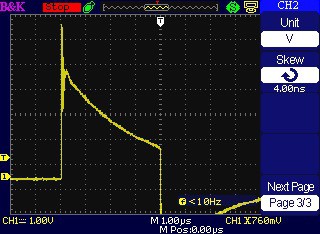
My fears were confirmed when I recently destroyed all twelve LED's during an ill-designed experiment. This led to further research and the discovery of an incredibly simple high-pass filter circuit - it's just a low-pass RC circuit, but with the resistor and capacitor swapped! Using a 100 nF ceramic capacitor and 1.5k ohm resistor, the circuit prevents the TC4452 drivers from activating longer than about 5 microseconds. Here's the driver's input signal:
![]()
The TC4452's datasheet indicates the input 'OFF' voltage to be 0.8 - 1.3 volts. Also, the minimum input voltage is -5 volts, so the signal inversion isn't a problem. As shown in the series resistor voltage shown above, the gate is not turning off before a 4-microsecond pulse is complete.
External Trigger Protection
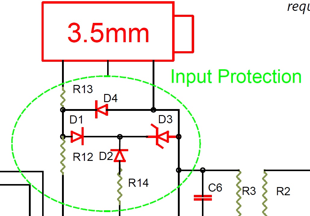
The original external trigger line was connected directly to the microcontroller's input pin. This is poor practice and would more than likely lead to a damaged microcontroller (or worse, activation and destruction of the LED's). Research into the topic of protecting the external input without affecting the signal response has led to the current design.
![]()
Several diodes are required, but fortunately the cost is not increased significantly. I have yet to actually test the new design for any delays introduced and its ability to protect the controller. As such, the design may be updated in a future revision.
Piezo Buzzer
Previously, in order to ready the flash, the user was required to press the button and watch the display until the flash was charged. The board is now equipped with a piezo buzzer. This simple addition gives an audible confirmation of the unit's readiness during use. Four fast beeps indicates to the user that the flash is ready, so the user is not required to stare at the display to confirm it successfully entered the ready state.
The buzzer is optional, and the firmware will include a switch to disable the pin. If the buzzer is not used, the pin should be tied to ground.
-
Major LED Failure!
06/03/2019 at 03:41 • 0 commentsThe Incident
After days of torture-testing a single LED before it even started to show evidence of damage, I managed to fry all twelve LED's in a single unintentional event. That's $80 bucks of electronics GONE!
I felt like Mark Watney from The Martian (the scene that happened in the novel but was sadly missing from the film... If you read the book, you know the part). To quote XKCD:
I have never seen a work of fiction so perfectly capture the out-of-nowhere shock of discovering that you've just bricked something important because you didn't pay enough attention to a loose wire.
The event happened while I was experimenting with a switching regulator. I hoped to decrease the number of AA batteries required, so I grabbed a boost regulator from eBay and set it to 12 volts. Then powering the boost regulator from a 5V power supply, I started testing current draw during operation. So the LED's functioned before these tests, but didn't work afterwards.
---------- more ----------The saddest part is that I never even saw the final flash, since the unit was face-down on a table. Some deduction leads me to infer that the LED's must have been cycled during the testing, during which time a power fluctuation must have occurred which caused the microcontroller to reset. During the reset, the controller continued to activate the gate driver, resulting in a prolonged flash at 110 volts which resulted in complete failure of all twelve LED's.
Lessons Learned
The failure taught me two things.
- The power supply system of Edgerton simply requires 8+ volts of battery voltage. Using lower input votlages and a small boost regulator can cause catastrophic failure, and a high-capacity regulator will probably result in too much inefficiency.
- A hardware circuit to prevent prolonged LED activation is more important than I first thought. I investigated such a circuit before constructing Edgerton and didn't find a good solution. But given the expensive loss of the components, I need to revisit the issue.
Future Actions Planned
Aside from the failure (which was a result of ill-planned testing), Edgerton has proven to be robust and functional. However, I want to continue developing Edgerton to improve performance, reliability, and ease of use. With that goal in mind, I've decided to eventually fork the project into two similar sub-models.
- The current model will not see any major modifications and will be referred to as the Classic. I like the sound of Edgerton One, but it would seem to be too similar to its most prolific competitor...
- The Classic will retain the same case design, 8-battery supply, and much of its controller design.
- The relay will be replaced with an opto-isolated P-channel MOSFET, the ringing in the MOSFET gates will be addressed, and a duration limiting circuit will be added.
- On completing these objectives, the design will be finalized and development will begin on the next sub-model.
- The next sub-model will be referred to as the Mark II.
- While the Classic was designed to be easily fabricated by anyone with a 3D printer and soldering skills, the Mark II will be designed with the potential for mass production in mind. The components will be more optimized and may include hardware that isn't as easily assembled by hand.
- The Mark II will retain the LED layout, driver circuitry, and (probably) the UI of the Classic.
- The primary design goal will be the ability to run from four AA batteries (3.2 - 6.0 V, 1.0 A max, 200 mA typical). This will require a complete redesign of the electronics and modifications to the case design.
-
Phosphor LED Turn-Off Time
06/01/2019 at 20:14 • 1 commentThe Potential Problem
I've received a few comments regarding the type of LED that Edgerton uses. Specifically, the LED's may not turn off fast enough. This is a problem I didn't really consider previously, given a statement in the Cree application note (pp. 10: The typical turn‑on time for an device is on the order of 10 nanoseconds or less). Since they turn on in 10 ns, why can't they turn off as fast?
Well, it turns out that the LED's use a little trick to make white light. The actual LED modules make a blue light, and a layer of phosphor in front of the LED's turn the blue light into a spectrum of light ('white light'). While the LED's can turn on and off quickly, the phosphor is delayed in turning off (and maybe on - I don't know yet). Notably, Edgerton's primary competition (Vela One) appears to use a similar type of LED and the manufacturer defends their flash durations on their website.
Experimental Proof Of A Minor Problem
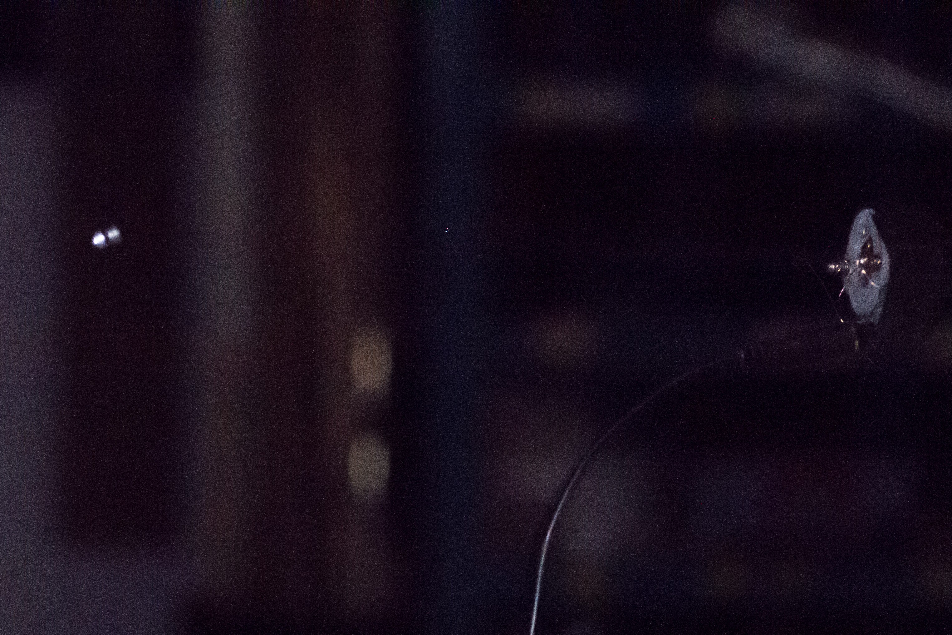
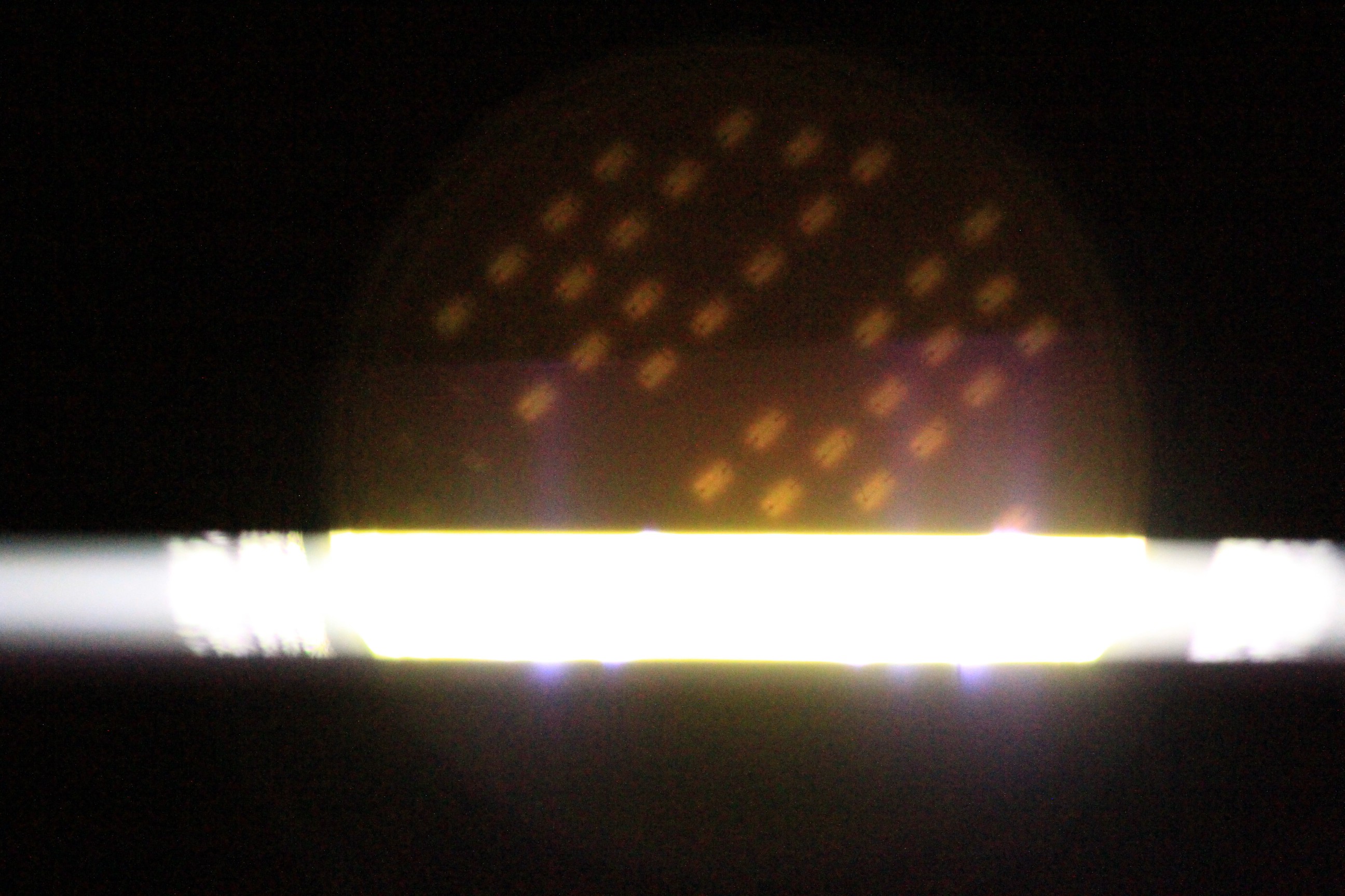
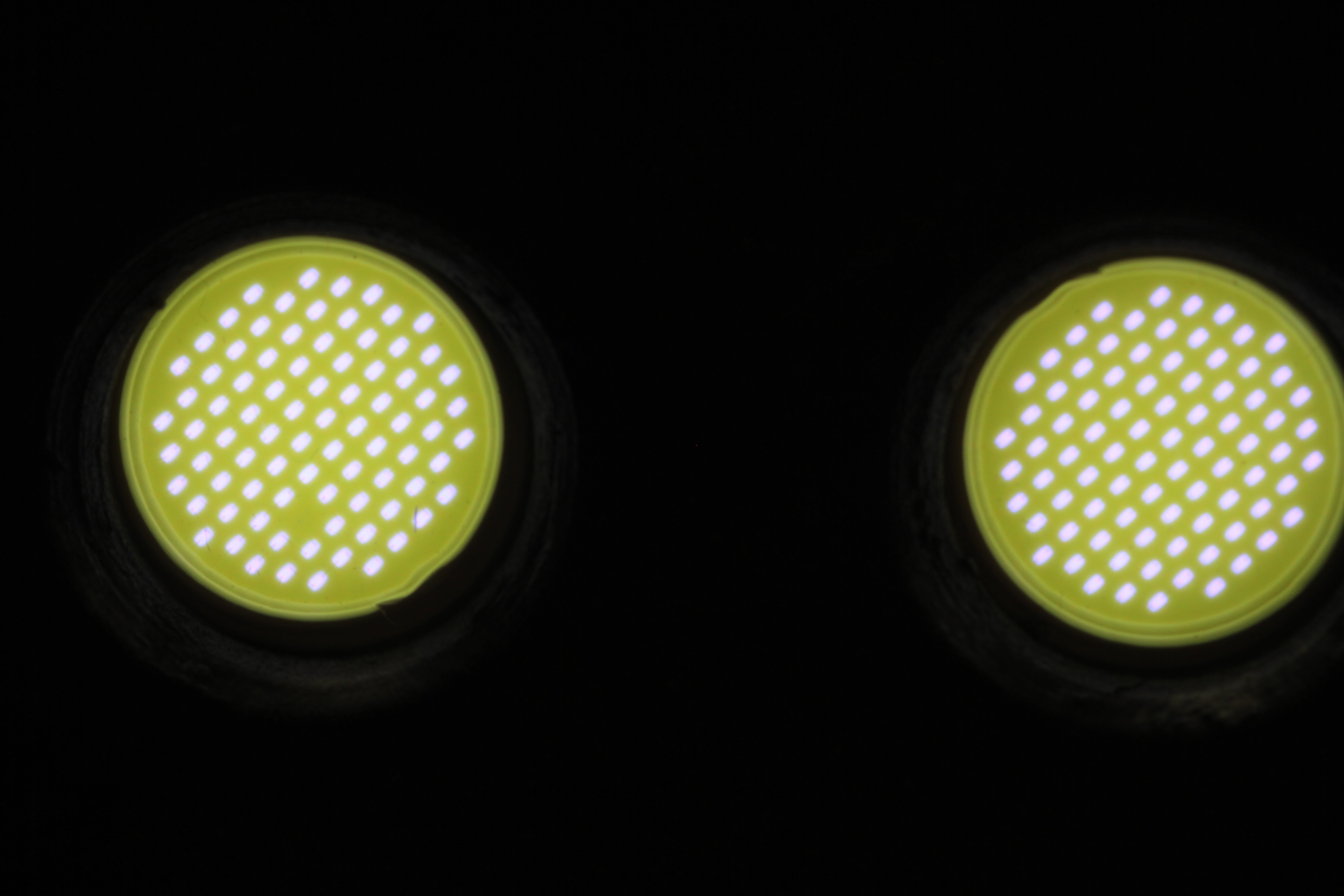
Here's an experiment that demonstrates the problem. It's a photograph of the LED flashing a 1-microsecond pulse. There are three stages of the flashing cycle observed here: The bright strip of light is the 1-microsecond flash, the illuminated dots above are the LED modules AFTER the flash, and the darker area below are the LED modules BEFORE the flash.
![]()
There were MANY failed attempts to take this photo. Ignore the absent LED modules, this was a damaged chip. Before explaining how this image works, I'll explain what it tells me. The LED's above the flash strip show that there is some lag in turning off. But during the turn-off time, the phosphor doesn't output much light. In other words, the LED is incredibly bright for one microsecond, but then becomes dimly lit for some time afterward.
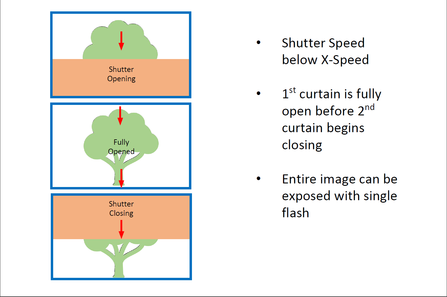
---------- more ----------Now an explanation of the image. DSLR cameras have a focal-plane shutter that has a 'rolling effect'. At shutter speeds below the 'X-Speed' (about 1/200th of a second), the bottom shutter opens completely before the top shutter begins closing.
![]()
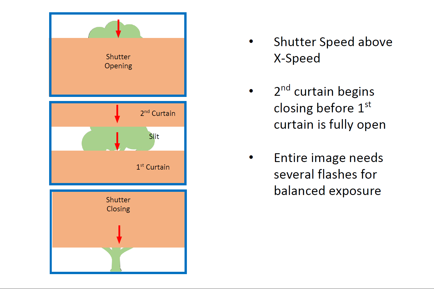
At faster shutter speeds, the top curtain begins closing before the bottom curtain is fully opened. The photograph of the LED was taken at 1/8000th of a second (fastest speed for many DSLR's, including my 7D).
![]()
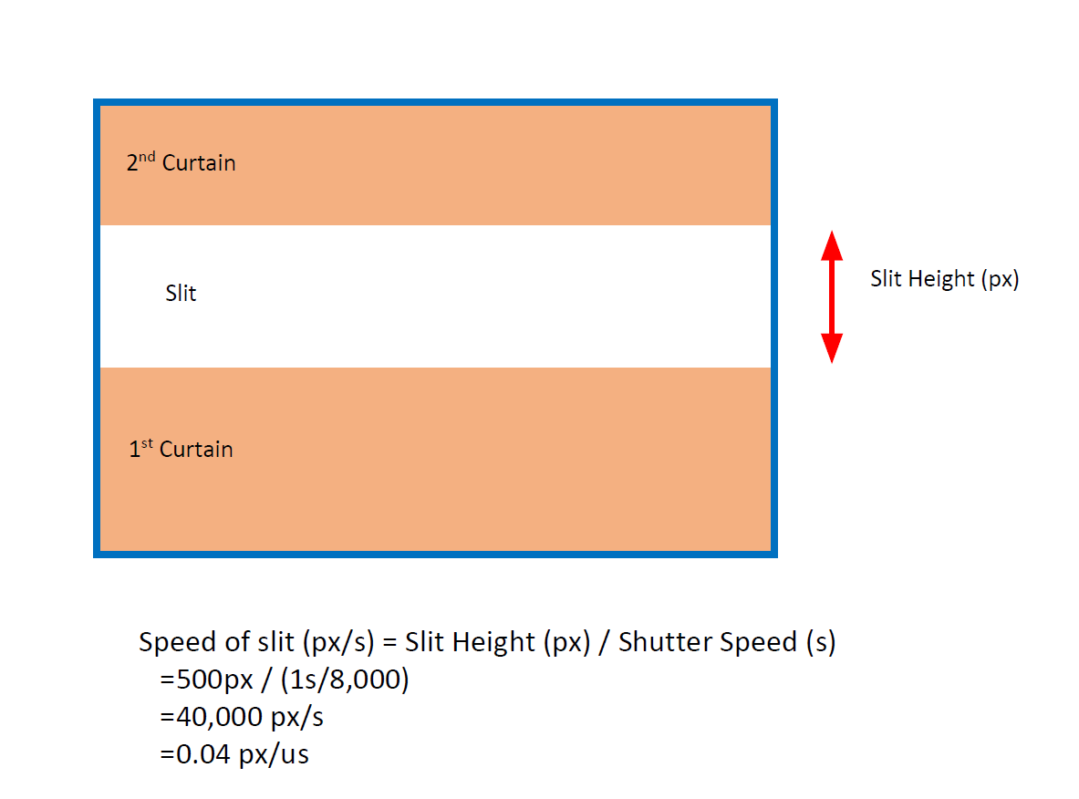
So the slit is moving at a rapid speed, and the bottom part of image was actually exposed before the top part (since the image is inverted, the shutter curtains move down while the image is moving up). So applying some math, we can give the image a timeline.
![]()
The flash is much too quick to calculate the flash turn-on and turn-off time using this method (0.04 pixels per microseconds!), but since the LED's at the top of the image are still partially illuminated, we can definitely say that the turn-off time is greater than about 1/8000th of a second (125 microseconds). We can also say that the illuminated LED modules are FAR dimmer than the slit of light, so it doesn't seem to be a problem.UPDATE 2019-06-05 - I was thinking about this on my commute and realized the math must be wrong. The shutter is moving 4 px/microsecond! That's actually fast enough to determine the turn-off time with better testing.
A Better Experiment
Directly measuring the light output over several microseconds would require some specialized equipment. Thankfully a fine community member, NQTRONIX, has graciously offered some assistance and the use of an active light-measuring probe which can work with my oscilloscope. I will update this project when testing with the active probe is complete.
-
150,000 Flashes Later
05/29/2019 at 02:25 • 0 commentsStrobing the LED's at several times their rated voltage is one thing, but a good flash needs to have a useful lifespan. I began testing the lifespan of the unit a couple weeks ago. Testing was done using only one LED (too expensive to risk multiple LED's) strobing at 1 hZ. I started at 70 V, cycling 10,000 times at 1 microseconds and 5,000 times at 4 microseconds. The LED was aimed at an 18% grey card 20 cm away and a DSLR photographed the card every 20th flash. After the LED cycled 15,000 times I incremented the voltage +5 V and started again. At 95 V, the LED showed no sign of quitting so I increased the flash rate to 2 hZ and photographed every 50th flash.
![]()
Well, it turns out that the LED could handle all the way up to 125 V - and I stopped the test as the circuit board wasn't designed for more than that! The photos were batch analyzed with ImageJ and no fluctuations in light output was observed. Above is a photo of the LED with 150,000 flash cycles vs an LED that didn't go through the torture test (0.3 seconds vs >0.001 seconds total illumination time). Interestingly a single element died at some point, but it still conducted current and light output was barely affected.
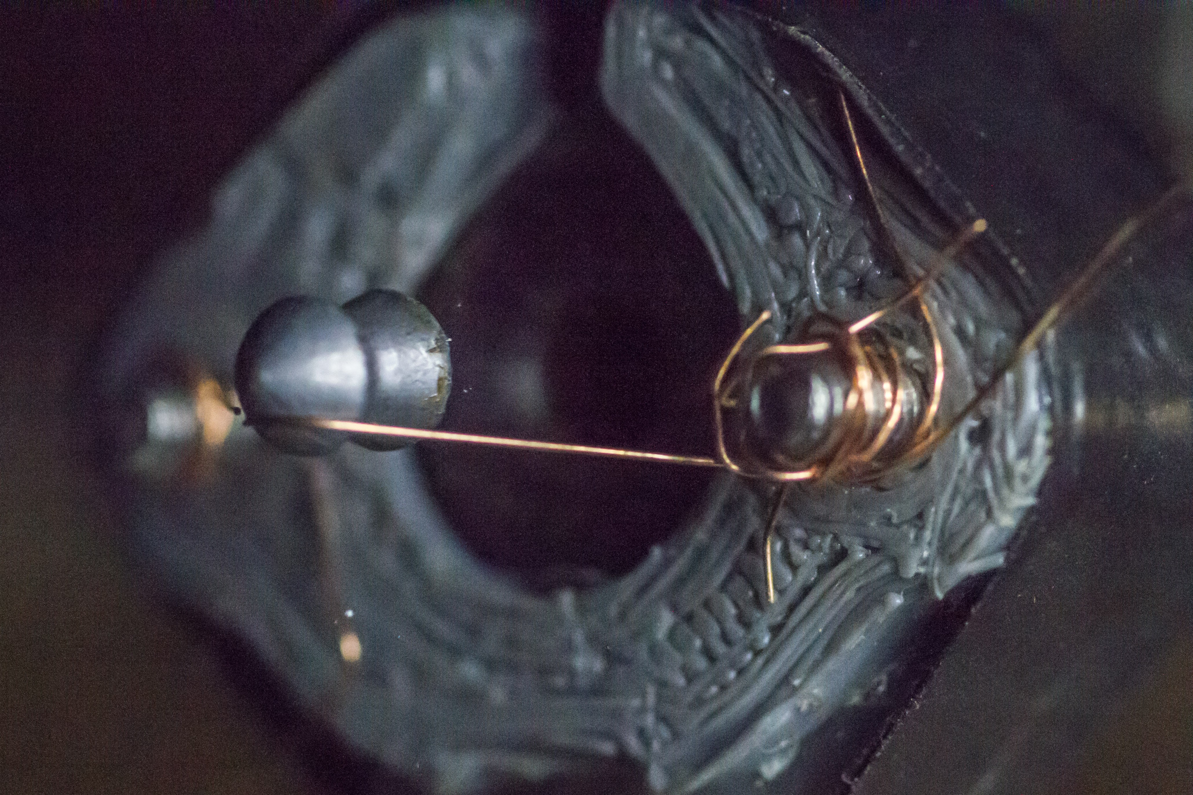
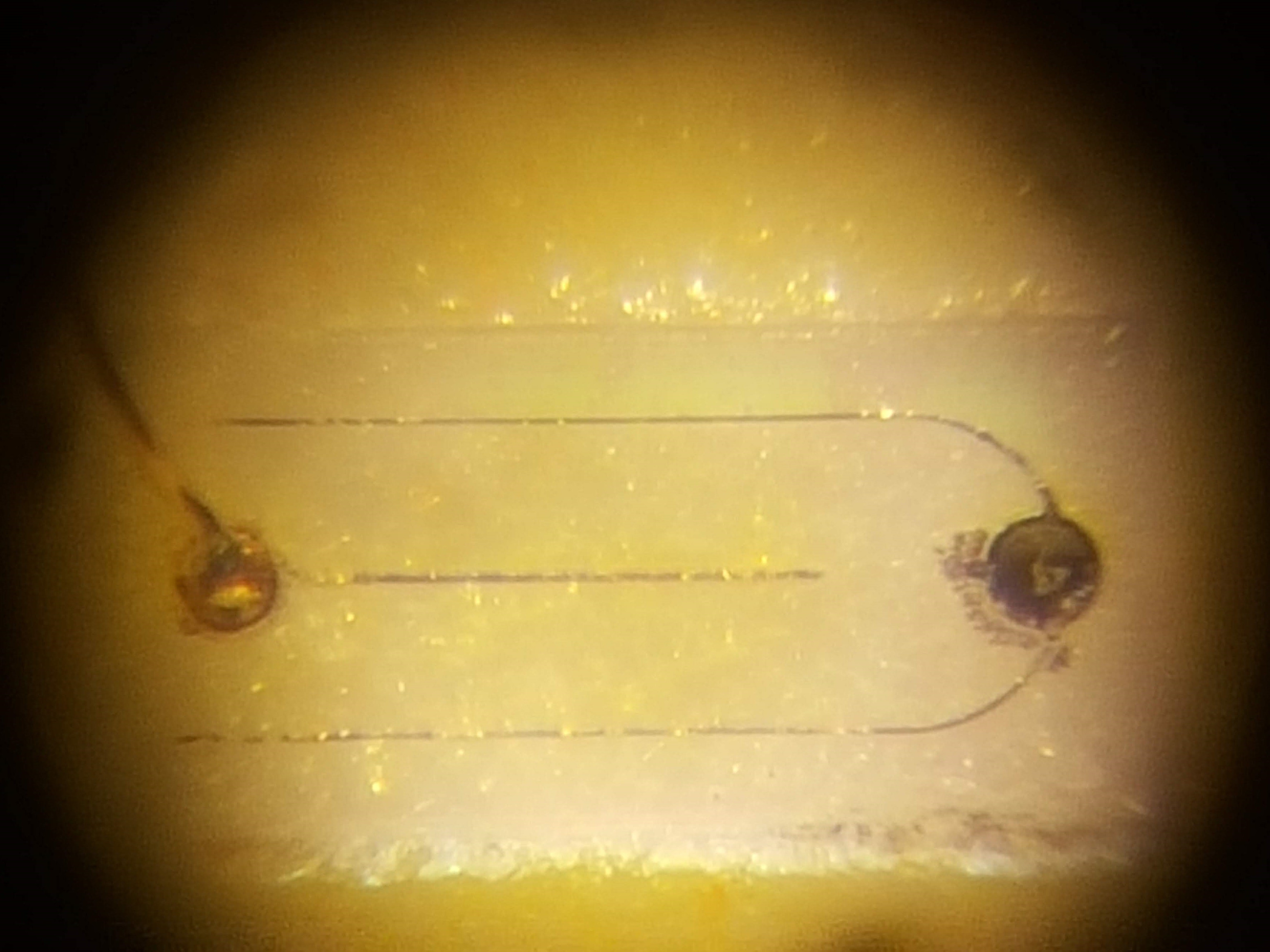
---------- more ----------Afterward I disconnected part of the board and began strobing at 20 hZ. I continuously increased voltage until the LED showed damage. It happened somewhere around 200 V (unfortunately I had an issue with the voltage measurements and am not sure exactly what the voltage was).
![]()
I peeled the potting material off the LED and put it under a microscope (photo above). The little wire on the left side connects the centre slot-shaped LED element to the next LED in the series (these LED's are actually several parallel sets of elements in series). The wire on the right was fried right off the the edge of the element!
Given the results of this testing, I've increased the driving voltage from 75 V to 110 V.
-
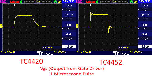
Voltage-Exposure Testing
05/25/2019 at 19:33 • 0 commentsShortly after assembling the device, I tested a bank (3x LED's) by increasing the voltage until the LED's were damaged. The test began at 45 V and incremented by 10 V following a single flash. Major damage occurred at 125 V.
More recently, I started a series of longevity tests with a single LED. It was strobed over 100,000 times at various voltages. Surprisingly, the LED reached 125 V and survived a battery of cycles at that voltage.
Some head-scratching later and I realized that the FET driver was changed since the original destructive testing (TC4420 to TC4452). The new driver could ground the MOSFET gates faster, shortening the pulse and probably preventing the LED from premature death.
![]() ---------- more ----------
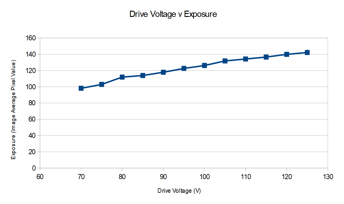
---------- more ----------The results of these tests will be posted shortly, but in the meantime I wanted to check whether the LED's output continued to increase at higher voltages. Testing consisted of about 4x strobes at 1 microsecond, starting at 70 V and incrementing by 5 V until it reach 125 V. The LED was positioned 20 cm from an 18% grey card and a DSLR photographed the card during the flash. Each image was cropped to 1000 x 1000 px and the average pixel brightness of that crop was calculated using ImageJ.
![]()
As you can see, the LED's output continues to increase with voltage. The control board could not exceed 125 V, so higher voltages need to be tested on a different board.
I'm currently building an integrating sphere for better measurements. When it's complete, I will repeat this test using the sphere. The current draw will also be measured using an oscilloscope.
Edgerton, A High-Speed LED Flash
Affordable photography tool used to capture images of bullets with no apparent motion blur