Close
0%
0%

The ultimate VGA to SCART adapter

15.7KHz composite sync generator for old arcade monitors and SCART TVs enhanced following visenri's indications

Public Chat
Similar projects worth following
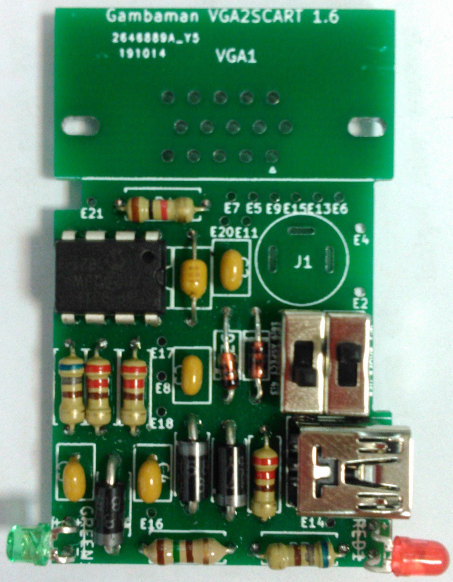
Accurate recreation of vintage arcades is becoming increasingly difficult. CRT monitors are rare nowadays and, even if you find one, it will probably not support the 15.7Khz horizontal frequency used by many old arcades. A good alternative is a CRT TV with a SCART connector. If your system has a VGA output and you can configure it to use an horizontal frequency of 15.7Khz then you can use this adapter to connect it to the SCART input of a TV. This project is an enhanced version of my previous adapter. Visenri told me I should use a PIC16F18313 so it could generate the status signal itself. The adapter is easy to make, unexpensive and powerfull.

This project is under the CERN-OHL-W licence described in https://cern-ohl.web.cern.ch/

Disclaimer: Use the information provided here at your own risk. I do not take any responsibility for any resulting damage.

This adapter is based in the cheap PIC16F18313 microcontroller following Visenri's indications. It has the following pros:

  • It automatically detects the polarity of the input VGA sync signals and configures the configurable logic cells (CLC) of the PIC dynamically to generate the SCART composite sync signal correctly.
  • If the frequency of the VGA horizontal sync signal is wrong or if the VGA vertical sync signal does not change then the PIC disables the SCART composite sync signal, the SCART RGB selection signal and the SCART status signal.
  • Most VGA devices can provide enough power to the PIC so no external power source is required.
  • No external power source nor DC-DC converter is required to generate the 12V of the SCART status signal. It can be generated by the PIC itself as noted by Visenri.
  • Optional aspect ratio selection.
  • Optional LEDs  to test the power and input sync signals.
  • Optional power source selection.
  • The basic circuit only requires the PIC and a pair of resistors and capacitors.
  • The full circuit fits in a (big) DE-15 enclosure using a single sided PCB and easy to solder through-hole components.

Pin outs

PIN #

name description
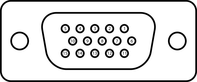
1 RED Red video
2 GREEN Green video
3 BLUE Blue video
4 ID2/RES formerly Monitor ID bit 2, reserved since E-DDC
5 GND Horizontal sync ground
6 RED_RTN Red return
7 GREEN_RTN Green return
8 BLUE_RTN Blue return
9 KEY/PWR formerly key, now +5V DC, powers EDID EEPROM chip on some monitors
10 GND Vertical sync ground
11 ID0/RES formerly Monitor ID bit 0, reserved since E-DDC
12 ID1/SDA formerly Monitor ID bit 1, I²C data since DDC2
13 HSync Horizontal sync
14 VSync Vertical sync
15 ID3/SCL formerly Monitor ID bit 3, I²C clock since DDC2

Table 1: Pin out of a female DE-15 connector functioning as a VGA output from wikipedia
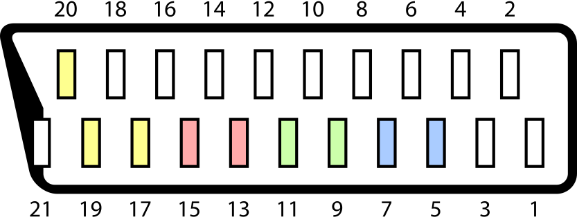

PIN #

description

1 Audio output (right)
2 Audio input (right)
3 Audio output (left/mono)
4 Audio ground
5 Blue ground
6 Audio input (left/mono)
7 Blue
8 Status & Aspect Ratio
0–2 V → off
+5–8 V → on/16:9
+9.5–12 V → on/4:3
9 Green ground
10 not used in this project
11 RGB Green
12 not used in this project
13 Red ground
14 pin 8 ground
15 Red
16 RGB selection
0–0.4 V → composite
1–3 V → RGB
17 Composite sync ground
18 pin 16 ground
19 Composite sync output
20 Composite sync input
21 Shell/Chassis

Table 2: Pin out of a SCART connector from wikipedia

Connections

2.1 Common ground

The HSync ground (VGA pin 5), VSync ground (VGA pin 10), ID0/RES (VGA pin 11), status ground (SCART pin 14), composite ground (SCART pin 17), RGB selection ground (SCART pin 18) as well as the ground of the PIC and the external power sources (if used) must be wired together.

2.2 Power source

In this project, the PIC requires a power source of 5V.  If the device generating the VGA signal is not very old, it will probably provide 5V through the pin 9 of the DE-15 connector. If it complies with the DDC host system standard then it will supply at least 300 mA, which is enough to power the whole circuit. So, you can probably connect the Vdd pin of the PIC to the VGA pin 9 and you will not need an external power source. Just in case, I included a switch and a mini-USB socket in the circuit so the power source is selectable. If the switch is in the left position, the PIC is powered by the VGA pin 9. Otherwise, it is powered by a external power source through the mini-USB connector. It is advisable to connect decoupling capacitors between the supply pins of the PIC to ensure it works properly. The manufacturer recommends two capacitors of 0.1μF and 0.01μF in parallel.

... Read more »

vga2scartFirmware.X.production.hex

compiled firmware

x-hex - 1.18 kB - 07/28/2020 at 19:41

Download

main.c

firmware source code

x-csrc - 7.83 kB - 07/28/2020 at 19:40

Download

ayuda_corte_carcasa_all.zip

Zip Archive - 9.50 kB - 04/25/2020 at 18:57

Download

KiCad_ultimateVGA2SCART.zip

KiCad project files

Zip Archive - 1020.46 kB - 11/04/2019 at 12:37

Download

ultimateVGA2SCART1_6.zip

GERBER files for the PCB

Zip Archive - 44.60 kB - 11/04/2019 at 12:35

Download

  • 1
    Program the microcontroller

    Flash the PIC using this compiled code.

  • 2
    Get the printed circuit board

    You can order it (for example at JLCPCB or ALLPCB) or make it yourself using these GERBER files.

  • 3
    Solder the componentes

    Do not solder the DE-15 connector nor the jack socket yet. Otherwise it will be difficult to solder the SCART wires.

View all 10 instructions

Enjoy this project?

Share

Discussions

SCART VADER wrote 05/19/2024 at 14:32 point

I am happy to see they are selling another variant here: https://ultimatemister.com/product/ultimate-vga-to-scart/

  Are you sure? yes | no

Rion wrote 03/25/2023 at 12:46 point

Is it possible to improve the resolution switching even further? Having issues in games that switch resolution in game from 240p to 480i (in-game to Menu) in Retroarch using the switchres api 2.0

Final Fantasy 7

Resident Evil 2

Dino Crisis

To name a few.

  Are you sure? yes | no

SCART VADER wrote 11/29/2021 at 00:28 point

I have just created a project with an alternative implementation: https://hackaday.io/project/182801-vga-to-scart-box

  Are you sure? yes | no

SCART VADER wrote 05/02/2021 at 18:06 point

Aitor has combined his MonochromeVGA project with my VGA-SCART adapter to get the MonochromeRGB.

  Are you sure? yes | no

SCART VADER wrote 05/02/2021 at 18:02 point

I am happy to say I have found two stores selling implementations of this adapter.

One is https://www.arcadexpress.com/es/arcadevga/457-cable-arcade-vga-scart-usb-5v-12v-con-audio.html
This implementation looks almost identical to the original, except the position of the LEDs.

Another one is http://vga-scart-converter-f-15.mozello.es/catalog/params/category/0/item/1443803/
The appearance of the latter is quite different. The switches are more accessible so that the power supply or the aspect ratio of the screen can be changed without having to open the adapter. Another notable difference is that it has a female VGA input and two SCART outputs, one male and one female. The adapter can be connected directly to the TV with the male SCART connector. Alternatively, it can be connected via the female connector using a SCART cable.

UPDATE: I have been allowed to release the design files of the alternative implementation here: https://hackaday.io/project/182801-vga-to-scart-box

  Are you sure? yes | no

SCART VADER wrote 07/28/2020 at 19:44 point

I have modified the firmware just a bit so it will not wait for so long before activating the output.

  Are you sure? yes | no

SCART VADER wrote 02/08/2020 at 15:38 point

They have asked me in several forums if the adapter was sold in a store. Since the design is "libre", nobody needs my consent to make and sell it. However, I would appreciate a message from anybody willing to sell it so I can link a supplier in the project page.

  Are you sure? yes | no

[deleted]

[this comment has been deleted]

SCART VADER wrote 02/08/2020 at 15:30 point

49mm*30mm. I got 5 PCBs for 1.83€. You can download the GERBER files and the firmware from this site.

  Are you sure? yes | no

SCART VADER wrote 12/30/2019 at 17:09 point

Somebody is polling to make a batch of adapters: https://www.offidocs.com/loleaflet/dist/loleaflet.html?service=owncloudservice13&file_path=file:///var/www/html/weboffice/mydata/8378688565/NewDocuments/9072788666.xlsx&username=8378688565&ext=yes

If you are interested you can ask the guy who is selling the adapter. Just send him an e-mail with the subject "ultimate vga" at rgbux666@gmail.com.

  Are you sure? yes | no

SCART VADER wrote 11/04/2019 at 15:36 point

I have uploaded a new version of the PCB (labeled 1.6) with the correct DE-15 footprint and the common ground connections. I have tested it and it works.

  Are you sure? yes | no

SCART VADER wrote 08/30/2019 at 21:44 point

I have uploaded a new version (labeled 1.4) with the correct footprint, but I haven't tested it yet. I will test it as soon as possible.

  Are you sure? yes | no

SCART VADER wrote 08/28/2019 at 18:24 point

I have just realized that the DE-15 was hard to fit because its footprint is not OK. The current published version of the PCB (labeled 1.2) has the wrong footprint. I will publish a fixed version as soon as possible.

  Are you sure? yes | no

Similar Projects

Does this project spark your interest?

Become a member to follow this project and never miss any updates