 David Reiss
-
1Structure
The code for this demo is all in https://github.com/dreiss/tiny_sump2_demo . Feel free to just check it out and skip ahead to the "hardware setup" step. The following steps will walk through the process of setting up the demo, so you can apply them to your own project.
-
2Empty project
Create an empty iCEcube2 project for the TinyFPGA BX. Here's an example: https://github.com/dreiss/tiny_sump2_demo/commit/f346374be9585d6685b93095d2c188df638d99c4
-
3Device under test
Implement a design that you'd like to debug. Here's an example: https://github.com/dreiss/tiny_sump2_demo/commit/4e65b2a6fdaa5d979a89089f3bb11d7f3e3f7cbe . Note the comment in stateful.v. The design has some internal state that we'd like to observe.
-
4Input source
Make sure your FPGA can receive input. Here's an example implemented as an Arduino sketch: https://github.com/dreiss/tiny_sump2_demo/commit/e5f6077bc92899bb048d97a2410bd87b14001d9a . Note that input should be generated fairly rapidly to avoid performance problems in the SUMP2 viewer.
-
5Logic Analyzer Core
Add the unmodified SUMP2 code to your project: https://github.com/dreiss/tiny_sump2_demo/commit/b44aaa4e1f6bd9acc8881914415f8a6c288a2bb9
-
6Update clock speed
The TinyFPGA BX runs at 16 MHz by default, so update these parameters: https://github.com/dreiss/tiny_sump2_demo/commit/a7aa9b1ef792d252a55b8bb7fc01e95469b2e2c4
-
7Add glue code
The original SUMP2 code has a top module that includes both internal wiring and external connections. Encapsulate the internal parts into a reusable module: https://github.com/dreiss/tiny_sump2_demo/commit/6e28a942095cf98aa77c2cadb6ee6d3b6625115e
-
8Integrate design and logic analyzer
We need to hook the logic analyzer up to our clock, external serial lines, and any 16 data wires that we want to observe. Note that the "dot" notation used to capture "st.state" is not supported by Yosys 0.8, so we can't use the Open Source IceStorm toolchain. See task https://github.com/YosysHQ/yosys/issues/647
-
9Get host tools
First, download the unmodified tools: https://github.com/dreiss/tiny_sump2_demo/commit/52c360c70c2ab0f97055d000e936cc4358a8aaa8
Fix Python 3 compatibility in error handling: https://github.com/dreiss/tiny_sump2_demo/commit/3dc05dd83aa38308e3411e6cc601db00fb71b10c
Fix compatibility with Linux: https://github.com/dreiss/tiny_sump2_demo/commit/913a3751182bab2649d68dd9a32e76e0676e9e29
Fix compatibility with non-FTDI serial cables and our lower serial speed: https://github.com/dreiss/tiny_sump2_demo/commit/cb3f0dbe635d9351ff0b808db2ec26012e6a58f5
-
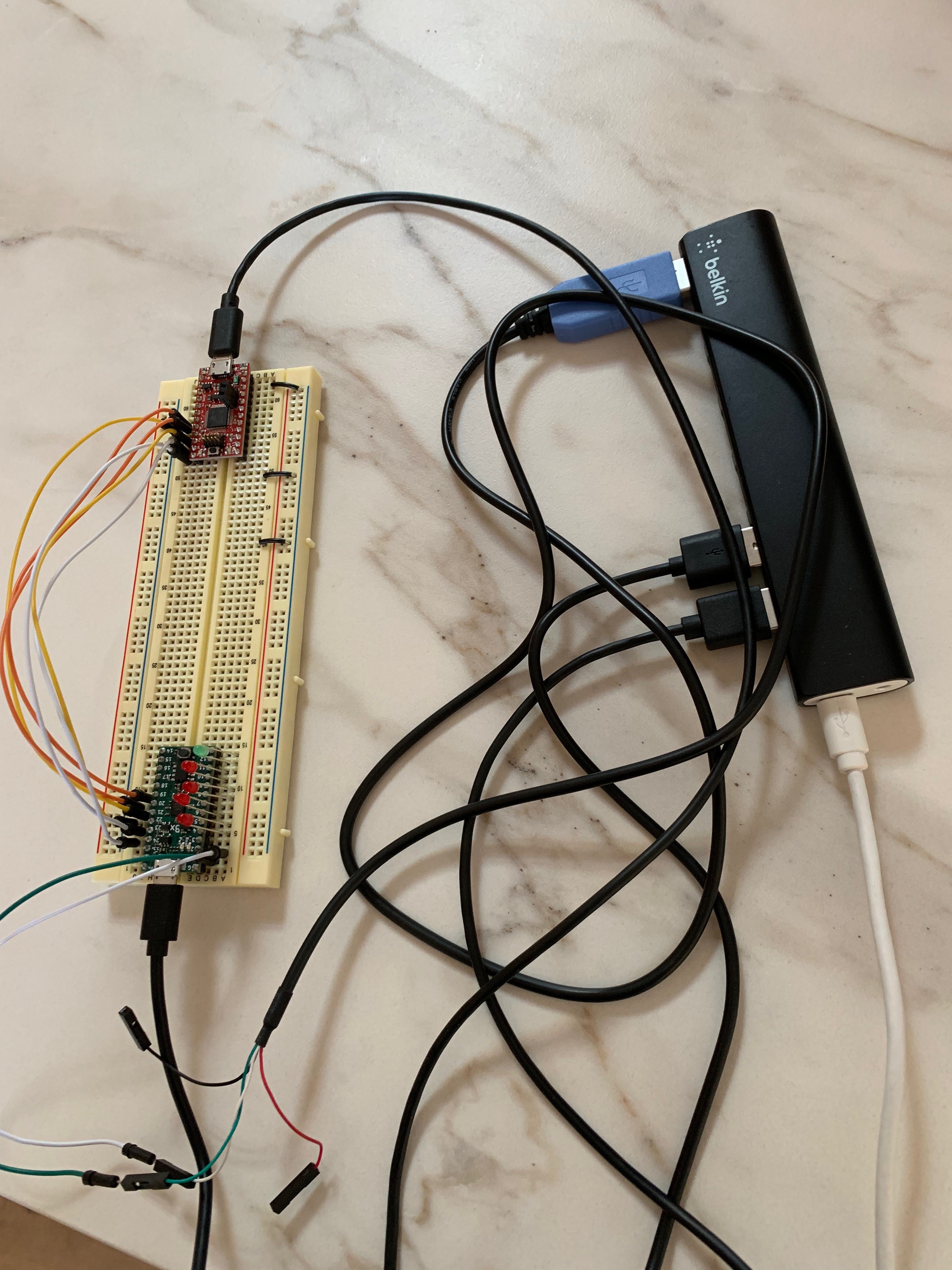
10Hardware setup
Install the Arduino sketch on your 3.3V Arduino. Install the design on your TinyFPGA. Wire them together according to the comment in the sketch. Plug LED anodes into data pins 4,,6,8,10 on the TinyFPGA. If you have LEDs with integrated resistors, you can plug the cathodes directly into pins 5,7,9,11. Plug the 3.3V serial cable in to data pins 1 (TX from computer) and 2 (RX to computer). The LEDs should blink rapidly. Here's a picture.
![]()
SUMP2 TinyFPGA Demo
Open Source Integrated Logic Analyzer in a TinyFPGA-BX project
Discussions
Become a Hackaday.io Member
Create an account to leave a comment. Already have an account? Log In.