3D Printed Robot Joint with Active Compliance
A general purpose robot joint using a cycloidal gearbox and an ODrive modified to support active compliance
A general purpose robot joint using a cycloidal gearbox and an ODrive modified to support active compliance
To make the experience fit your profile, pick a username and tell us what interests you.
We found and based on your interests.
Cycloidal Drive All v2.2.stlAll the 3D printable part for one Cycloidal Drive - updated drive designStandard Tesselated Geometry - 13.79 MB - 09/23/2019 at 17:48 |
|
|
Cycloidal Drive All.stlAll the 3D printable part for one Cycloidal DriveStandard Tesselated Geometry - 9.82 MB - 06/13/2019 at 21:46 |
|
I've just uploaded a revised version of the joint design. This comes after a fair bit of tinkering over the last few months. Partly I've just been tightening up the tolerances of various parts, but mostly I've been experimenting with keeping the cycloidal gears running more smoothly (so less friction) and more reliably.
The biggest change is in the cycloidal disks themselves. In the picture above you should see an extra 4 "bumps" added to the top of the gear. These replace the nylon washers used in the previous design and help keep the disks parallel while dramatically decrease the drives internal friction. How well they wear only time will tell but so far everything seems better!
I'm continuing to experiment with detecting external forces acting on the robot joint, something that seems fundamental to any form of compliance. At the moment I'm interested in a situation where the joint is under no load (a robot leg taking a step) and as it come into contact with an obstacle (the ground) it responds to the external force to "soften the blow" rather than remaining rigid.
But because everything in the system is noisy, doing this with confidence is something I'm finding challenging.
The graph above shows the minimum and maximum error (with decay) of a moving joint between the time when it receives an external force (which triggers movement) and comes to a stop (after a fixed period of time). Ignoring the start and end, the error is quite large and bounces around a fair bit due to the friction in the joint being non-uniform, errors in estimating joint velocity, and the ODrive doing its best to keep the velocity at a set point.
Here's another graph of the joint errors. This one contains more interesting events.
The red boxes highlight the points where the joint stops moving (without any external force) while the green boxes are points where an external force is applied to the moving joint. The first green box is for an anti-clockwise impulse, while the second green box is for a clockwise impulse. Note how, when an external force is applied, the error peak on one graph marginally proceeds the error on the other graph. This differs from the red boxes (where the joint comes to a stop without an external force) where the error only peaks on one graph. I think, maybe, that the way the errors changes might be a reliable way to detect, and respond to, an external force?
 I don't begin to understand where the load and stresses on this design are, but clearly there's quite a bit on the pins, and while they're made of metal, the cycloidal disks are just plastic. So this part needs to be reprinted with more infill and an increased number of perimeters. I originally just used 20% infill and 2 perimeters, so I'm going to up that to 50% and 6 and see how they new disks survive.
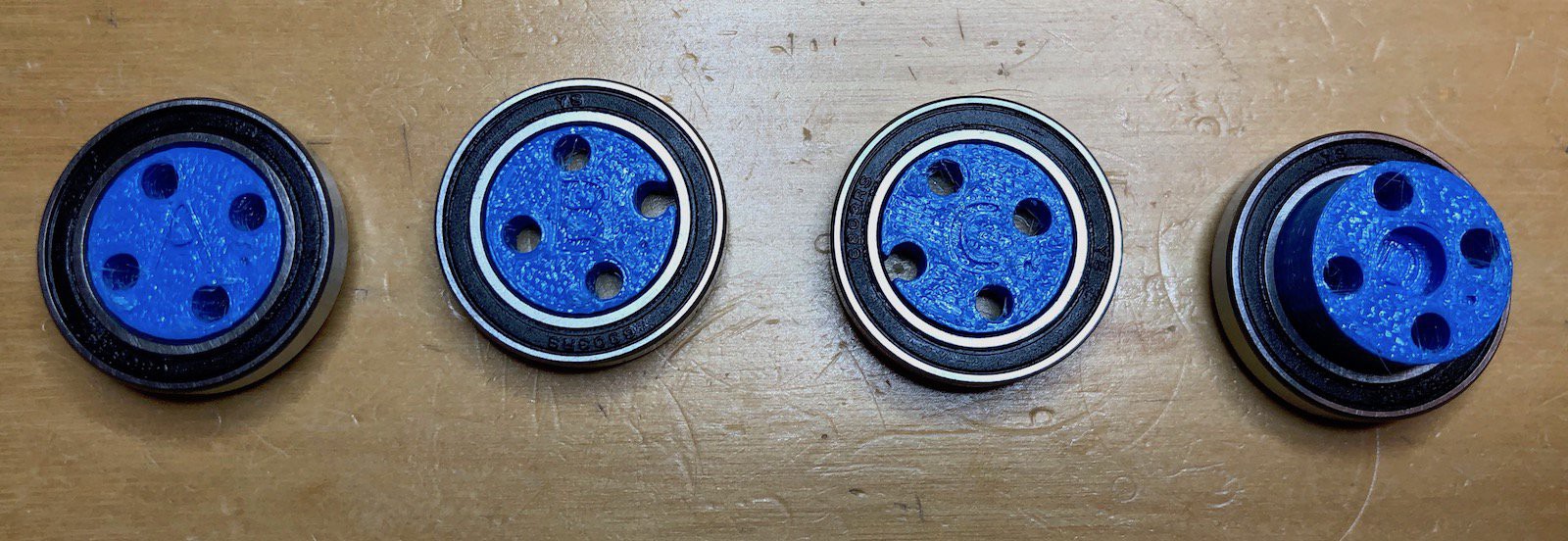
Next push the B and C pieces into the two cycloidal disks. It doesn't matter which way round these are mounted or which disk goes on which bearing. Push them on until they are flush with the bearing.
Now push the A and D bearings into the two "keyhole" shaped pieces. These pieces are identical. The A bearing should have the letter pointing "in" so you can see the holes in the piece, the D bearing should be pointing out.
Push the four M3 40mm screws though the center holes of the "A" bearing.
Add the larger bearing.
And insert the 8 pins into the holes. These should be relatively loose fitting.
On each of the pins, add a nylon washer. These washer will keep the final assembled parts parallel. While everything has a tight fit, 3d printed pieces will move when the joint is in use and these washers keep everything "true". Without them the joint tends to lock up over time.
Now insert the "B" part over the screws and pins. How these are lined up is important as you'll notice the holes in the A, B, C and D pieces are not all the same. Each pieces should be assembled so the A, B, C and D as all the same way up. There is also a small dot on the bottom/right of each letter. These should also line up.
Add 8 more washers.
And then part C, remembering to line up the letter and the dot.
Add then the final 8 nylon washers.
Now carefully place the "output" shaft (that's the circular collar part) around the cycloidal disks. You may need to wiggle it into place. It doesn't matter which way up it goes, and the exact position is unimportant.
Prepare part "D" by adding the remaining (large) bearing.
Then push it carefully onto the parts already assembled, again lining up the letter and the dot. This can take a bit of jiggling because you need to get all the pins and screws into their respective holes. Once you're done it will look like this.
Now we need to attach the motor. The 40mm screws are spaced to attach directly to the motor.
Carefully place the motor on top of the assembled joint such that the screws line up with the holes in the motor.
Screw the screws into the motor to secure everything. This can be fiddly and I sometimes have to rotate the motor body back and forth a bit as I "feel" where the screws go.
There's one final piece to add; to secure the motor to the rest of the joint. Push the motor mount into the hexagonal hole and rotate the base of the motor until it lines up with the holes on the motor mount. On these motors, the holes are not all at the same distance from the center.
Use the 4 small screws to attach the motor to the mount. One of these screws is shorter than the others and should be used in the "cut-out" on the mount. This cut-out is for mounting the rotational encoder (which I'll describe separately). You can probably get away without that short screw if you want.
And there we go.
The joint itself mounts onto 2020 aluminum extrusion.
If all has gone well, if you rotate the motor by hand the joint should move. You should also be able to rotate the joint by hand and make the motor spin.
To assemble one robot joint you'll need for following printed parts:
Almost every part is unique, except for the two outer supports (those keyhole shaped parts with the 8 holes in a circle). You will also need a few extra pieces of hardware:
These are (with Amazon links):
You also need a motor. I'm using these:
A complete set of 3d printable parts for one robot joint easily fits on the print surface of a Prusa i3. I'm using a recently upgraded Prusa i3 Mk2.5s and printing with Matterhackers PETG Pro filament. The total print time is about 10 hours (0.20mm layer height, 20% infill, no supports).
While you can print the parts without supports, some parts do include a little extra material to help them print, and this needs to be removed before assembly. Specifically, some bridges and bolt holes need tiding.
In the photo above, you should be able to see the bridge across the bolt hole on the left hand part, and the big supporting bridge on the middle part. Below you see the same parts with the bridges removed (using drills and craft knives as appropriate).
Finally, you might find a little stringing on the parts, especially on the internal surface of the output drive.
In reality, you could probably just leave this as it'll be quickly worn away once the joint is used. However, to keep things tidy, it can be eliminated using a hot air gun and will look muck cleaner as a result.
Just uploaded the STL to print one robot joint. Assembly instructions to follow as soon as I finish writing them.
Perhaps unsurprisingly, this turns out to be hard when you don't start knowing a whole heck of a lot about this stuff. And my internet search haven't turned up much that is helpful (I continue to search).
After much tinkering, this is where I am:
// Detect if the axis motion deviates from what we expect and adjust the motion.
// We track the position error against the maximum displacement, and if it deviates too much we conclude
// an external force is acting on the axis.
pos_error_ = fabsf(encoder_pos_estimate - controller_pos_setpoint) / (1 + fabsf(max_pos_));
if (pos_error_ > config_.error_band) {
    // Recalculate the trajectory based on the new position.
    // Currently this assume the velocity is reduced to ~0 when at the central point of its oscillation.
    period_ = sqrtf(1 / config_.elasticity);
    max_pos_ = encoder_pos_estimate - pos_setpoint_;
    max_vel_ = -max_pos_ / period_;
    tick_ = 0;
}
// Damping due to kinetic friction.
float kfriction = max_vel_ * config_.kinetic_friction * current_meas_period;
if (fabsf(kfriction) < fabsf(max_vel_)) {
    max_vel_ -= kfriction;
    max_pos_ = -max_vel_ * period_;
}
// Bring axis to a halt once velocity falls below static friction.
float interval = 2 * PI * tick_ / period_;
if (fabsf(max_vel_) < config_.static_friction && interval <= PI && (interval + 2 * PI / period_) > PI) {
    max_vel_ = 0;
    max_pos_ = 0;
}
// Calculate the new position and velocity
axis_->controller_.pos_setpoint_ = cosf(interval) * max_pos_ + pos_setpoint_;
axis_->controller_.vel_setpoint_ = sinf(interval) * max_vel_;
// Tick, wrapping as necesssary
if (tick_ >= period_) {
    tick_ -= period_;
}
tick_+= current_meas_period;
This code can be divided into three parts:
Of these parts, the first is the one still giving me the most problems. Accurately detecting an external force to a nominally oscillating actuator without extra sensors has proven difficult. The current solution tracks the position error in relation to the current maximum actuator displacement, and if a threshold is exceeded, recalculates the compliance. Unforuntately, this value needs to be tuned depending on other parameters and I'm unhappy with that.
Also, while this works relatively well for a "bare" motor, once the cycloidal gearing is added, the compliance adjustment works very poorly. This seems to be related to the default way ODrive manages the motor current (just fine normally of course) with position and velocity errors, and I will need to do more work here. Right now it can only handle small external deflection and that's not great.
Anyway, if anyone has thoughts and comments I'd love to hear them.
Upgraded the encoders to AS5147 which gives 4096 encoder counts per revolution vs the AS5047 which gave me 2000. Can't hurt.
The video above shows some experiments I'm doing in compliance, allows me to vary the static and kinetic friction of the system as well as the elasticity of the actuator. At this point I'm really just feeling my way as to what is possible (as well as trying to remember A-level physics and math).
These experiments simplify the final system quite a bit. For one thing, they assume a short impulse is applied to the system (provided by hand-model me) rather than the joint coming under a continuous, varying force. Also, the compliant system isn't kicking in until the impulse is removed; and finally, the impulse is applied when the system is at rest. Baby steps.
One of the bigger challenges will be detecting the external forces (e.g. a robot leg hitting the ground) being applied and separating them out from the planned movement of the actuator, especially as everything will be quite noisy. In these experiments the system is idle so that's rather easy. I'm hoping the tracking changes in actuator position, velocity and acceleration, and how these differ from planning will be enough to give me the necessary information.
Finally, although not shown in the video, all software runs on the ODrive itself.
Create an account to leave a comment. Already have an account? Log In.
I really like the one piece output housing. I've copied that part of your design and give credit where it is due. Thanks.
Great idea! Active compliance in a 3D printed cycloidal drive is what I have been thinking for a long time. Looking forward to your test results!
I will putting up the 3d files and other assembly information once I've stopped tinkering with them. Stay tuned.
Very cool -- are the files for the 3d-printed cycloidal assembly available anywhere? I'm curious as to implementing colloidal or harmonic drives into the four-legged robot platform I'm working on in the future.
Become a member to follow this project and never miss any updates
By using our website and services, you expressly agree to the placement of our performance, functionality, and advertising cookies. Learn More
 Michael G
 CLo
CLo
 jellmeister
 Quinn Morley
Hey, thanks for sharing, you saved me a hours designing a AS5047-5010 motor mount!