it does not only supply food but it also gives exact doses as decided by us; basically, at a preset time, a cochlea at the base of the container will turn, and drop a certain amount of kibble in the bowl, regulated by a dedicated weight sensor.
In order to have this kind of functioning, my dispenser is composed of a mechanical and an electronic section; the former has been assembled with PLA, 3-D printed parts, while the electronic section is composed of an Arduino UNO board to which i have applied an RTC Shield, a specific shield with an LCD display, a model-making continuous rotation servo and a load cell; the latter is used to weigh the amount of dry food, and once we reach the desired quantity, the servo operating the cochlea stops. The LCD monitor is managed through pins 8, 3, 5, 6, 7 of the Arduino board; instead, the load cell is read through the A0 pin and it provides an analogue signal itself. For simplicity of design, i decided to use a shield dedicated to measurements and weight display, interfacing with Arduino UNO as indicated and connected to the load cell. The shield, called Weight Shield, mounts an eight-character, 2-line LCD display, which is used, in my project, for setting up the machine. Besides the display, we have the INA125 integrated, a high precision amplifier developed specifically for measurement instruments such as scales.
The load cell can weigh up to 1.000 g and its body is composed of aluminium alloy; the output sensitivity is 1 mV/V (±0,15mV) and nonlinearity (at full scale) is 0,05%;
User interface
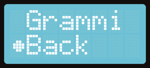
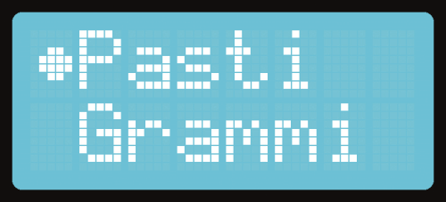
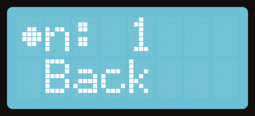
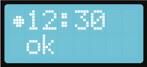
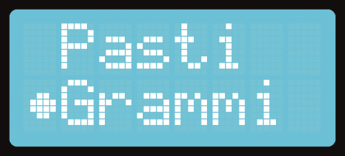
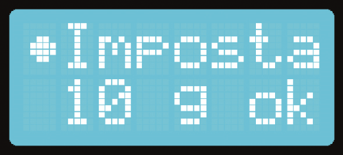
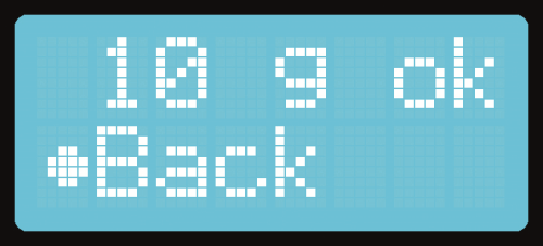
Now, let’s take a look at the user interface, composed of five keys and the display mounted on the Weight Shield; the keys functions are the following:
- P1 (down button): used to scroll the menu down;
- P2 (okay button): use to confirm options;
- P3 (decrease button): use to decrease number of meals;
- P4 (decrease button) use to increase number of meals;
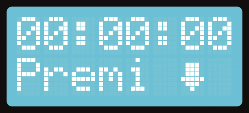
- P5 (dispense button); can be used only in the initial screen (Fig. 2), this key is used to manually distribute kibble whenever we want to add food beyond the preset dose, or to supply food anytime.
Mechanical structure
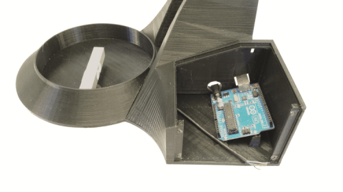
The electronics section is placed in the base, 3D printed as the rest of the mechanical structure. In the base we have placed the Arduino, the shields and the keys, on the right in the dedicated compartment, to be connected as below
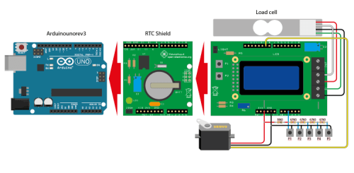
and to be mounted on the cover which you will secure using small self-threading, 2,5×10 mm metal screws; the cover has been printed with the holes for the five keys and the window for the display. Still inside of the base, in the section below the actual dispenser, you will fasten the marble plate to the load cell using two screws, which cell must be then applied to the base; on the moving plate, you will place the bowl that will collect the kibble.
The latter is to be 3D printed, provided that its base is smaller (in diameter) than the moving plate placed on the load cell and it is short enough to avoid touching the rest of the structure. The weight is not important in fact, the firmware calculates the tare, which is then subtracted to the detected weight when the kibble is dropped in the bowl.
Shows the exploded view of the structure
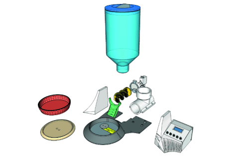
and shows an internal view of the mechanics, especially for what concerns the kibble dispensing mechanism, based on a spiral element actioned by the servo.
 Alessandro Sottocornola


That is cool; where do I feed 3D Model files for printing parts? Regards