Close
0%
0%

Recreating the Jupiter Ace

Recreation of the 'Fastest computer in the Universe' that runs FORTH.

Public Chat
Similar projects worth following
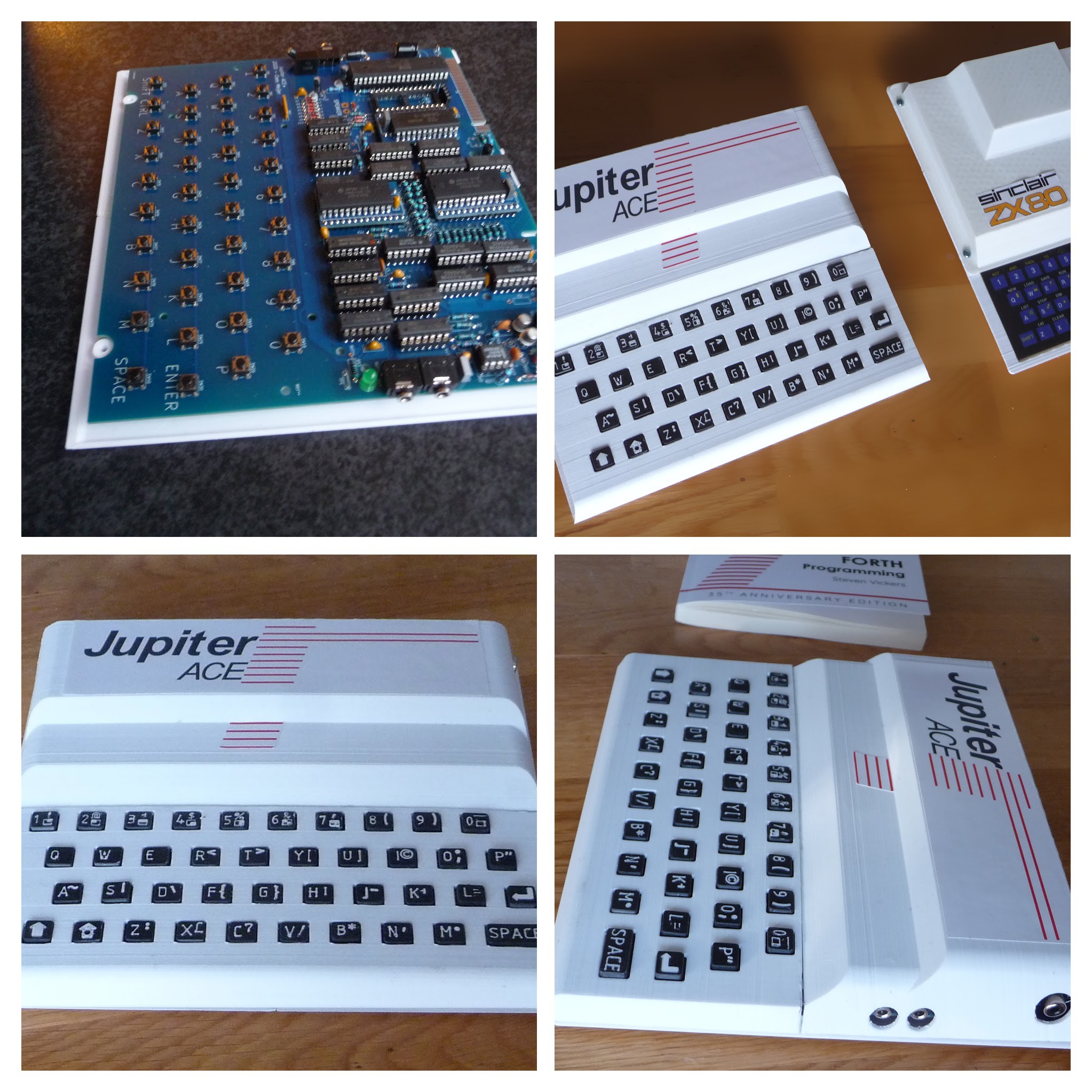
The Jupiter ACE was introduced in 1982 by a company named 'Jupiter Cantab' as 'probably the fastest computer in the universe'. Mainly because it was the first (and only) home computer at the time that ran Forth as it's main operating system. Since every other computer ran BASIC this was a remarkable choice, and it turned out to be a bad one. Only hardcore programmers dared to take up FORTH, and in the end only 8000 units were ever sold. Making them very rare and expensive nowadays so creating a replica is the closest I will ever get to owning one.

Building a replica of the Jupiter ACE  has been done before, and the super accurate replication of the PCB by Grant Searle is probably the best example. The schematics were redrawn later by Bodo Wenzel in ORCAD, and a modified version was made by Isidro Nuñez Blanco De Arenas. Both builds were done 2003-2006 ( which shows if you look at the design of their websites), and things have changed a bit since then. PCB manufacturing is much cheaper now, and it's also easier to create custom plastic parts. Because what's lacking in all these rebuilds is the actual housing, which to me is a huge part of the charm of this machine. And using a 3D printer it cannot be too hard to replicate this.

Actually, since I started creating this, some others have popped up (or I just did not find them at the time). There used to be a kit sold from Bulgaria by 'oricfan' but that one is hard to find these days. The most recent 'ACE' compatible kit is called the 'Minstrel 4th' by Tynemouth Software. Which is probably good, but (as mentioned on the site) is just a board, and will not fit the original Jupiter ACE housing.

There is the Jupiter-II, a beautiful version consisting of two separate PCBs. Which (as far as I can see) was created somewhere 2019-2020.

And of course I recently discovered that  people on the Jupiter ACE section of the K? Forum have created an almost identical board, in about the same time-span (2019/2020). They chose to use Cherry keys for the keyboard, which definitely will be a huge improvement in usability, but does not really add to the authentic look and feel.

Update 2024:

Scott Baker made a really nice video on building the unit:

He actually explains the whole thing better than me, and is worth watching if you run into problems with the video or character generator.

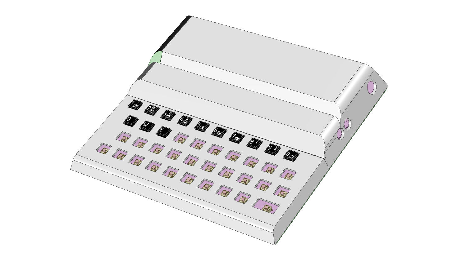
The Housing

To my surprise there were also no 3D models available , apart from the 'mini Jupiter ACE', which obviously is too inaccurate to use as a basis for a real housing.

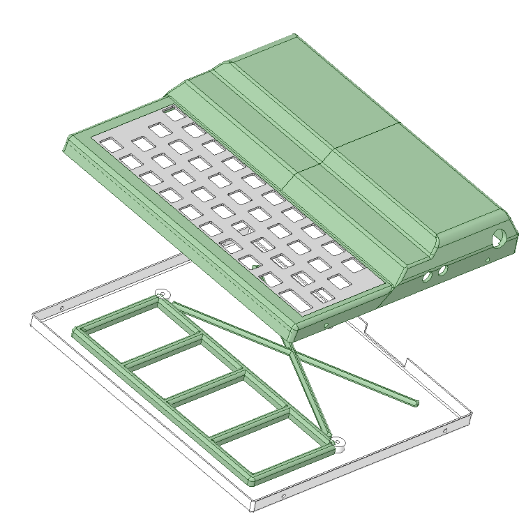
So I started out to do this myself, using my favorite 3D modelling software: 'DesignSpark Mechanical' (DSM). I used Grant's PCB layout, made it into a .png image and imported that into
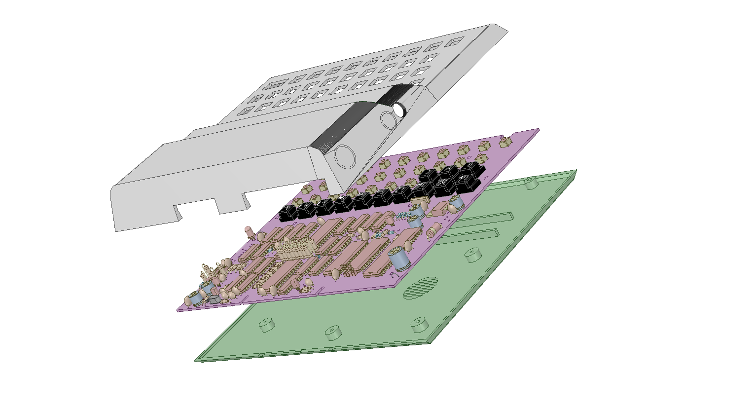
DSM. Since the drawing includes millimeter marks on the edge it was easy to scale it to exactly 100%.

The final design is now available on PrusaPrinters:

https://www.prusaprinters.org/prints/62264-jupiter-ace-replica

The Keys

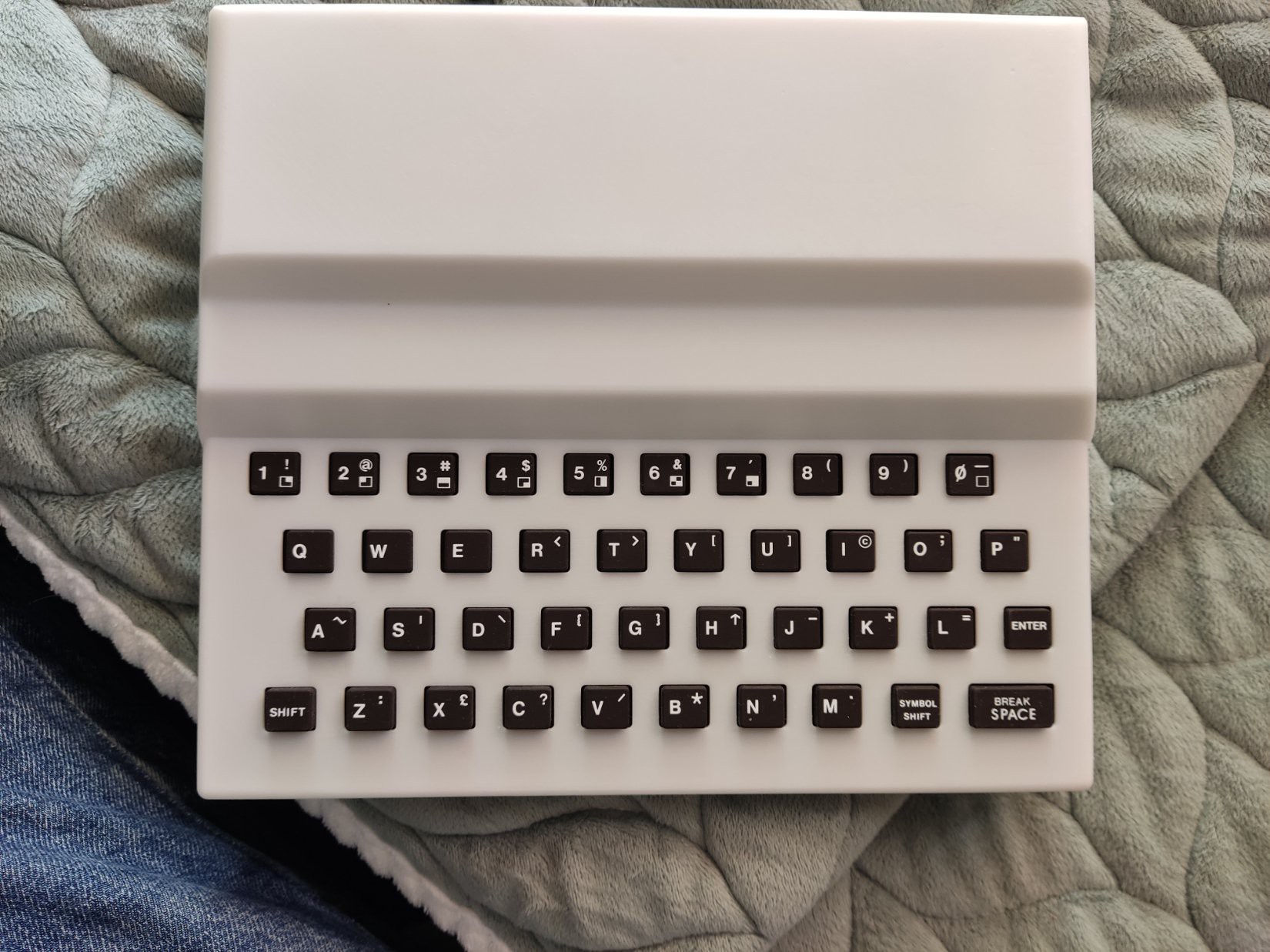
That's a hard one. Getting a custom made rubber key-mat is beyond my financial capacity so that's not an option. I'll try to make them using my 3D printer. The main problem here is  to get the text on the keys. I considered printing this on adhesive film and just stick it on top of the key. Then I thought I could also print the keys in white, with the text sticking out. Then if I spray painted them black and sand the top it would reveal the text again. 
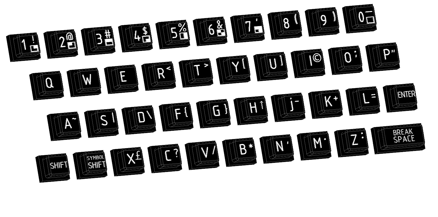
Which worked fine. Except for the smaller fonts like on the Enter and Shift keys. So for the final design I also created an alternative set with larger font, and the Enter and Shift keys as symbols.

Again, all design files for both keys sets available here, or on PrusaPrinters.

The PCB

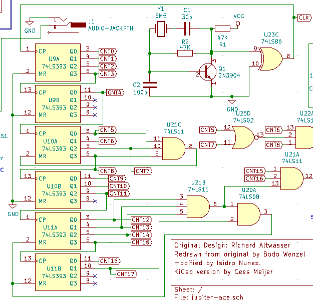
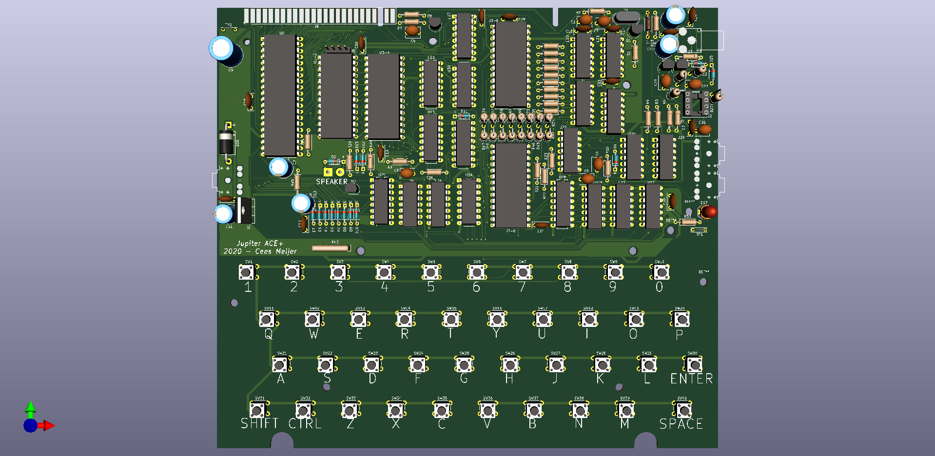
Though it's possible to create the exact PCB replica using Grant Searle's PCB foils, that is not what I wanted. I did want to make some minor changes on the EPROM and RAM connections, and use standard mini switches for the keyboard. Also if the PCBs have to be made by a cheap Chinese shop, it's essential to have Gerber files. So, all in all a good incentive to replicate the schematics again, but now in KiCad. For years KiCad has been a bit troublesome to use, but over the last few years it has improved significantly and is now a serious EDA package. It's free, open source and multi-platform so it is becoming the de-facto standard for all open-source hardware projects.
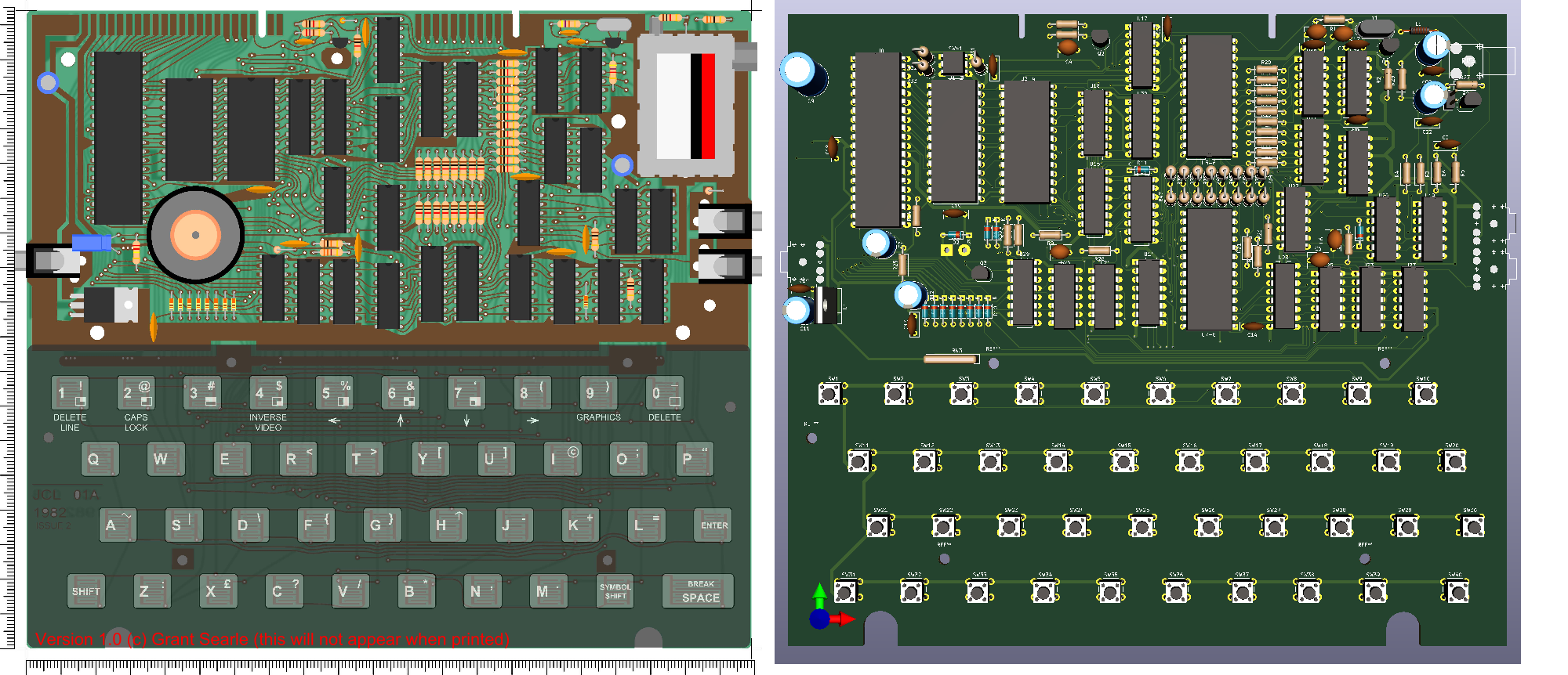
My board (on the right), next to the replica board of Grant Searle

Jupiter ACE BOM.xlsx

sheet - 21.19 kB - 02/20/2022 at 18:44

Download

Jupiter ACE BOM.csv

ms-excel - 3.51 kB - 02/20/2022 at 18:44

Download

Jupiter ACE Logo.svg

The Logo and red lines as on the housing. Designed in InkScape, not 100% accurate, but good enough.

svg+xml - 1.00 MB - 04/05/2021 at 13:18

Preview

Jupiter ACE Logo.pdf

PDF version of the the SVG file.

Adobe Portable Document Format - 5.06 kB - 04/05/2021 at 13:17

Preview

Jupiter ACE.rsdoc

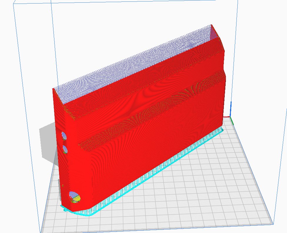
DesignSpark 3D file of the complete Jupiter ACE as built. Includes the PCB and the keys. Note that some parts (marked in RED) are actually only there to be used as support when printing the housing.

rsdoc - 35.90 MB - 12/14/2020 at 21:07

Download

View all 7 files

  • The 'Classic' housing

    Cees Meijer11/21/2022 at 21:37 0 comments

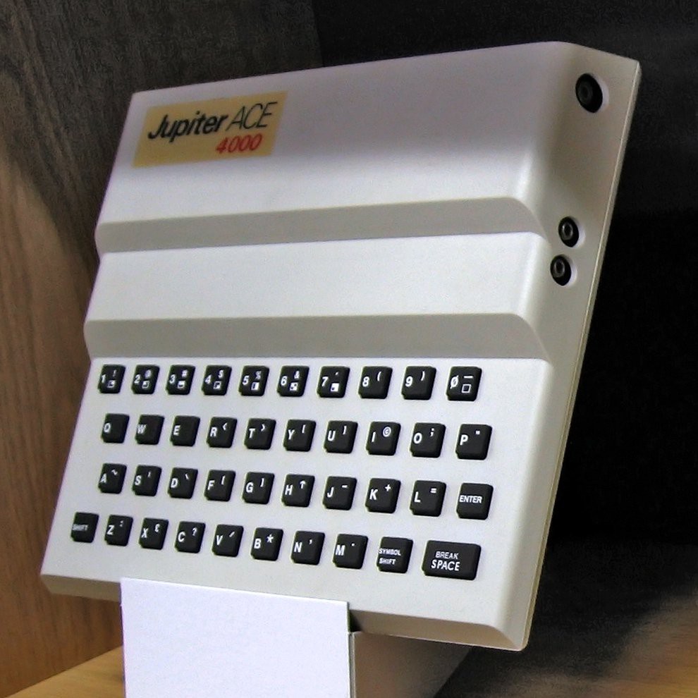
    The housing I created for my ACE is basically the housing as used on the ACE 4000 model.

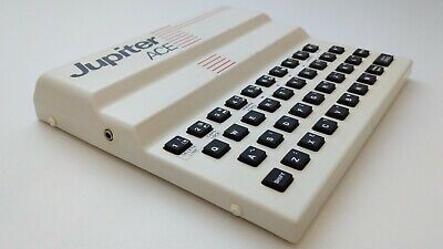
    This model was was made from injection molded parts, as opposed to the first ACE which was made using vacuum-forming.

    The difference is clear. The edges are smoother, and the top section just sits on the bottom section like the lid of a shoe-box. Five plastic pins then fix the top to the bottom, similar to how it was done on the ZX-80. Now i was actually quite pleased with my version, but recently Alejandro reached out to me. Apart from the fact he is also buiding an ACE clone, he also owns an original one. And he offered to send me some exact measurements on the housing so I could modify my model in such a way that it woud fit an original PCB and look more like the first ACE.

    So thats what I did:

    Its not perfect yet, and though it should fit my own PCB, it looks like the connectors on the original PCB do not line up, but its getting there.

    And it looks like it just fits my build plate:

    Lets see how that works out.

    But before I got round to printing it myself, Alejandro already had it printed at a professional printing service, and that looks really good:

    Here it holds the original ACE circuit board and keyboard. According to Alejandro the measurements are just a little bit off, but that does not seem to be a real problem here.

  • Switch off the Click

    Cees Meijer04/21/2021 at 20:41 0 comments

    Now the ACE is complete and functional I've started do do some programming on it. Which is what it's made for, after all. And so I run into an unexpected problem: the noise.

    The PCB switches have a nice, firm click. Which is good as feedback, but soon becomes annoying to other people in the room who are not so much into computing...

    The problem is that the PCB in the hollow plastic housing does a good job of amplifying each button click, so it is actually really loud. I've tried to dampen it by stuffing some soft cloth under the board, but this does not make much much difference.

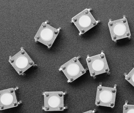
    So I've started looking for 'silent' switches. The first ones I found are these, sold by AdaFruit:

    These are 'Soft Silicone Top 6mm Switches'. So I ordered some, but found out that though the top is indeed soft, the click is not. It is equal, or maybe even sharper than the one I used.

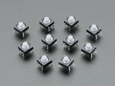
    Next I tried these 'Soft Tactile Button, 8mm'

    Which are indeed silent and produce no click at all. But the footprint is slightly bigger than the standard 6x6 mm switches, and they are slightly higher so they are not a 1:1 replacement.

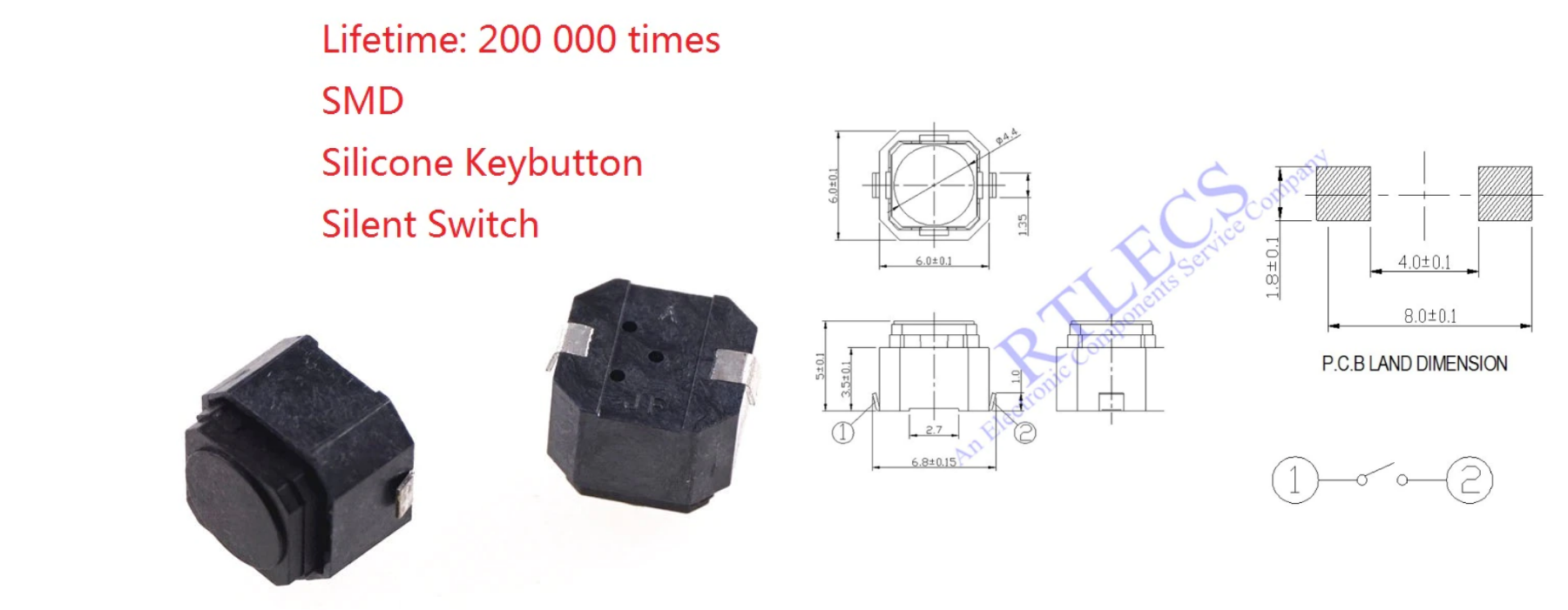
    Then I found these on AliExpress:


    Really small, and indeed very silent. And I think these are also very easy to use with the 3D printed keys since they are really square and the button itself is flat. The only disadvantage is that they are Surface Mount which will make assembly a bit harder.

  • Showing the Signals

    Cees Meijer04/18/2021 at 20:02 0 comments

    My system works fine, but it appears that others are building my design too. And to assist in fault finding it is probably a good idea to document some signals  so other builders can compare their results with mine.

    Oscillator

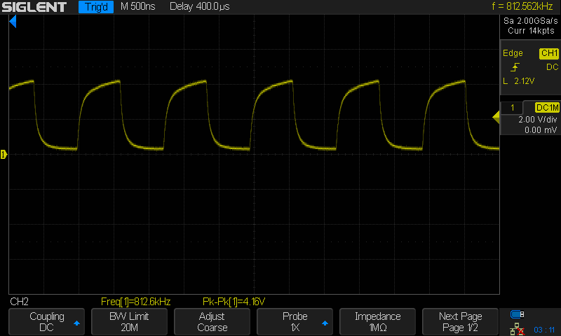
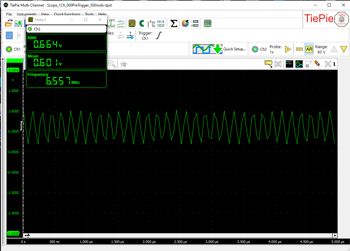
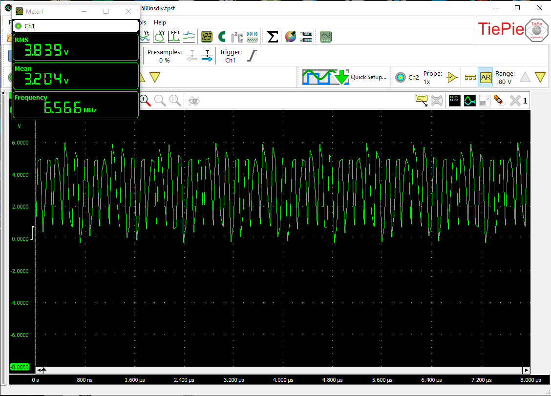
    Oscillator output:
    U23-8 Oscillator output 6.5Mhz
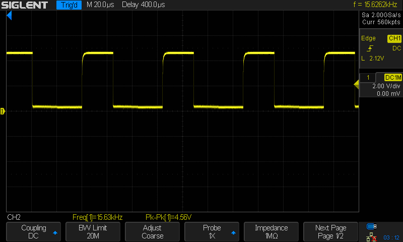
    U9-6 (CNT3)
    U10-6 (CNT6)

    Z80 - Pin 6 - Clock input
    U21-12 (FIELD) U19-11 (INT)

    Video Section

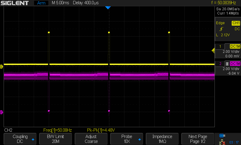
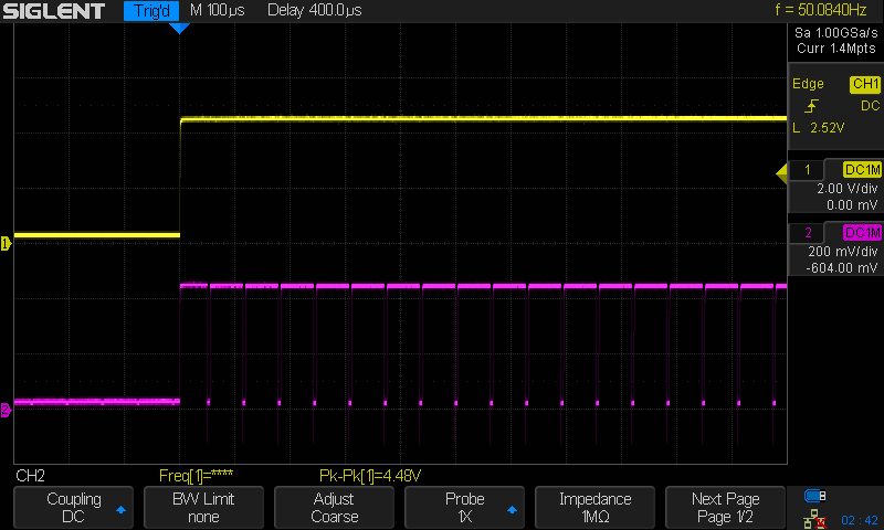
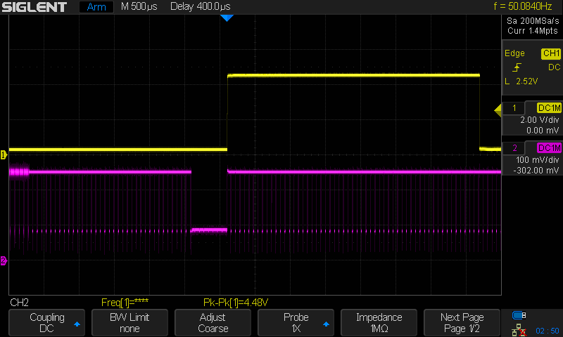
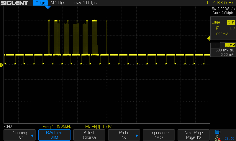
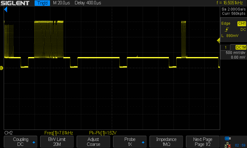
    Basis of the video signal is the 50Hz signal on U11-10. In the pictures below this is shown in the top, and used to sync the oscilloscope. Video signals were recorded with a LCD monitor connected.

    U11-10 (50Hz) - U25-11 (Sync)
    Base of Transistor Q5. Note the scale is 50mV/Div
    Base of Transistor Q4 - ( VIDEO )
    Cathode of D14, video output with a line of characters on the screen
    Close up of video signal

  • Video fix

    Cees Meijer12/07/2020 at 21:04 0 comments

    Though it finally works, the video output is not perfect. On my LCD screen it looks like all characters move sideways one or two pixels, about every 2 seconds. Very annoying. But it could be a LCD monitor issue, just not coping with this non-perfect AV signal. So I connected it to my TRS-80 monitor just to see if it would work better with a device that originates from the same era.

    Not really. Apart from the image being shifted to the left, all lines move slightly left and right like a wave is passing through the text.

    So, 50.0 Hz is important !

    Probing around with the oscilloscope I find the screen update frequency on pin 10 of U11. This is exactly 50.5 Hz, which might be the problem since that is exactly 0.5 Hz off from the required 50Hz, which could explain the 2 seconds period in the wave. I actually did not think this would be a problem on a modern monitor, but it looks like it is.

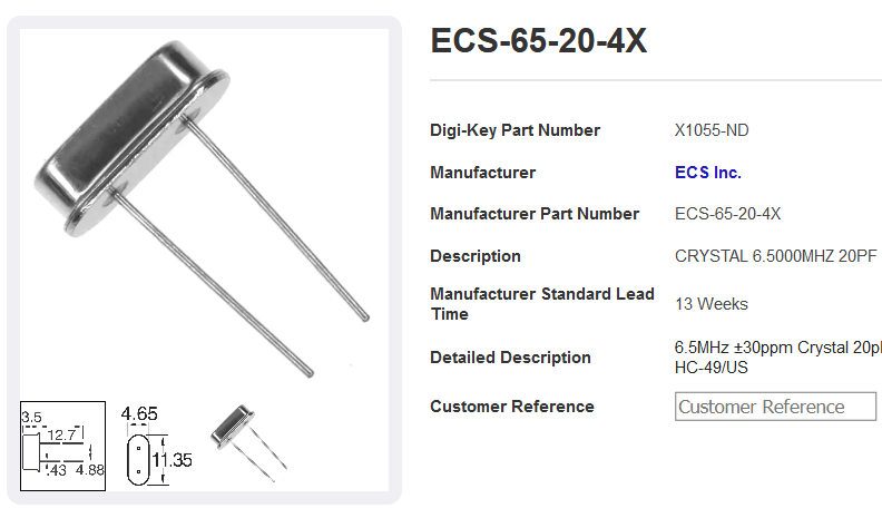
    The reason for this frequency to be off is the fact that I used a 6.5536 MHz crystal instead of the original 6.50 MHz, since that was the closest I could get from Reichelt. Maybe not such a good idea after all. A quick search shows that 6.50 MHz crystals are indeed not very common, but DigiKey does actually sell them.

    6.50 Mhz Crystal

    So I ordered 10 pcs. (they are not expensive). And indeed, after swapping the crystal the video image is rock steady and super clear.


    ( I just noted that @Ken Yap actually warned me for this when I started the project. And at the time I also answered to him that I could get the right crystal at Mouser or DigiKey. I just forgot about that later..)

  • It Works ! (all the way, this time)

    Cees Meijer11/29/2020 at 19:18 0 comments

    After deciding that I needed to change all logic chips from 74HC series to 74LS, I had to wait a week for the arrival of the new set. Nowadays I order all this from Reichelt Elektronik, a German company that has an amazing stock, and supplies components in any wanted quantity to anybody, business or private. ( Professionally I'm used to Farnell and RS, but these companies prefer only B2B) Great company, but delivery just takes 4 to 7 days.

    So after swapping all the HC chips for their LS equivalent, I had high hopes when switching it on. But alas: nothing changed ! :-(

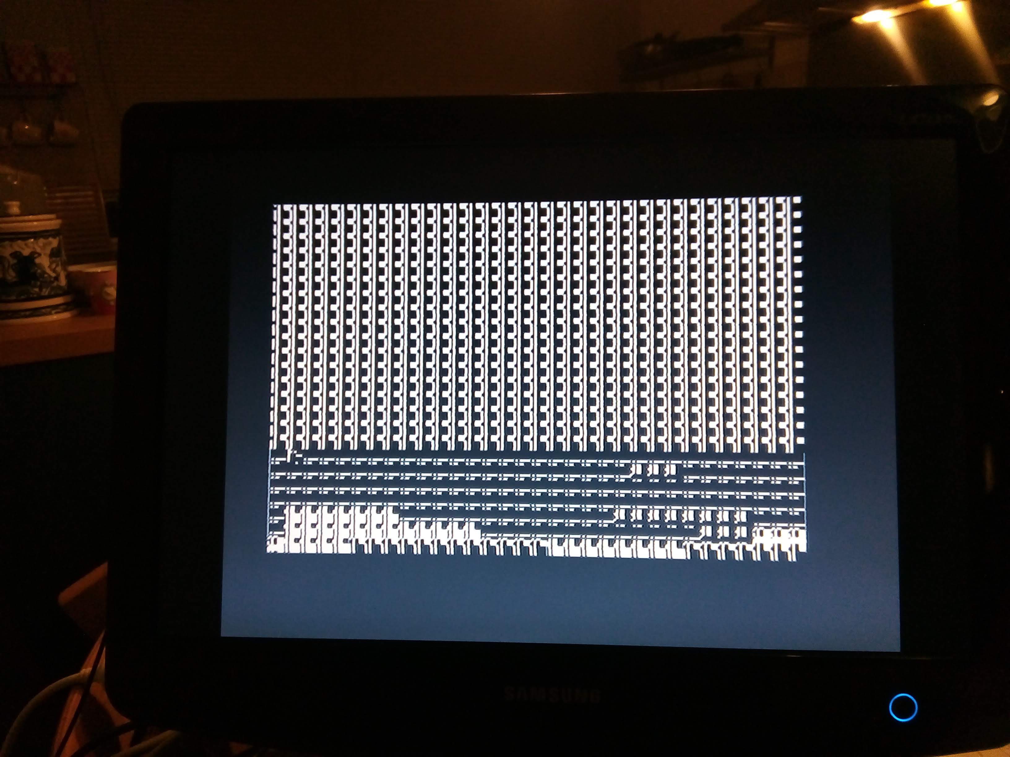
    Well, the oscillator wouldn't start due to the different impedance, but after I just changed this specific chip back to HC, it worked again. All signals do seem a bit cleaner, but it does not solve the problem. The screen still looks like this:Again: it does react to the keys, so everything seems to be functional, and this confirms my earlier suspicion that the fault must be in the writing or reading of the video memory. Which it was. Another check of the schematics showed that I tied the /CS signals of both video RAM chips together. Obviously not correct. And after fixing this by disconnecting the CS pin on one RAM chip and wiring it to the correct port, the computer showed me this:
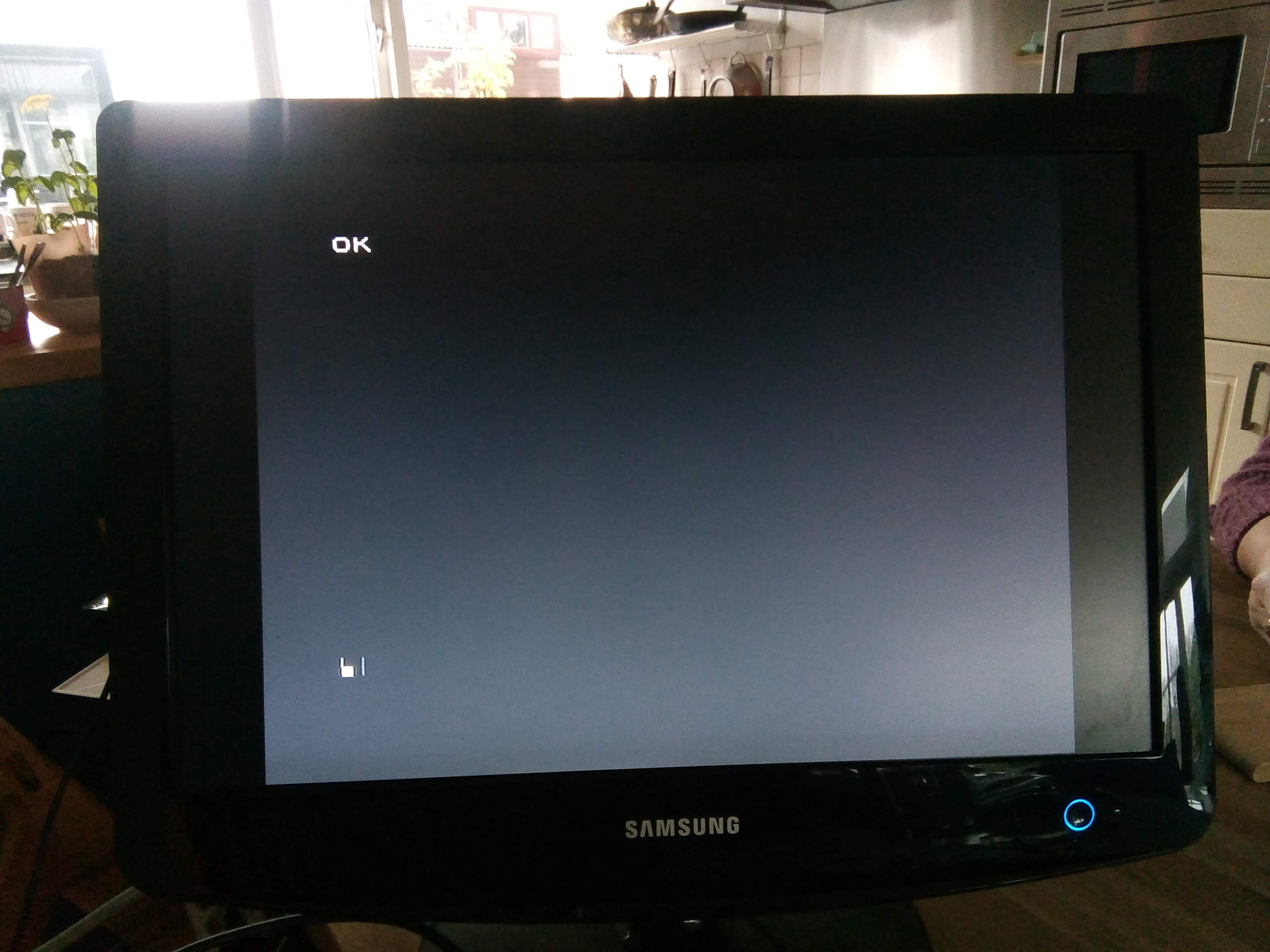
    YES !. That is what I was looking for !. Now let's try the only command I know: VLIST.
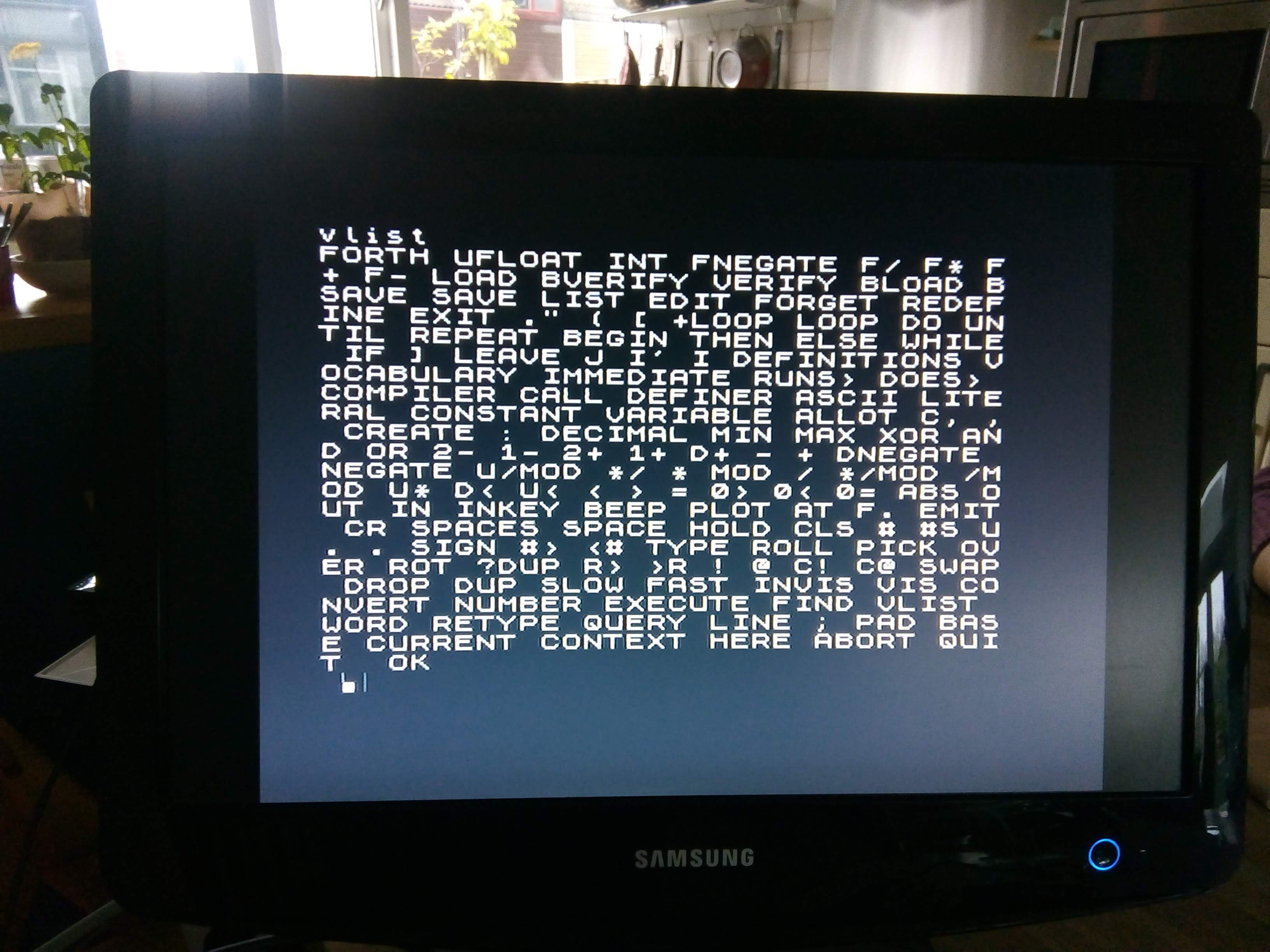
    EUPHORIA !. Finally, after more than 18 months, it works.
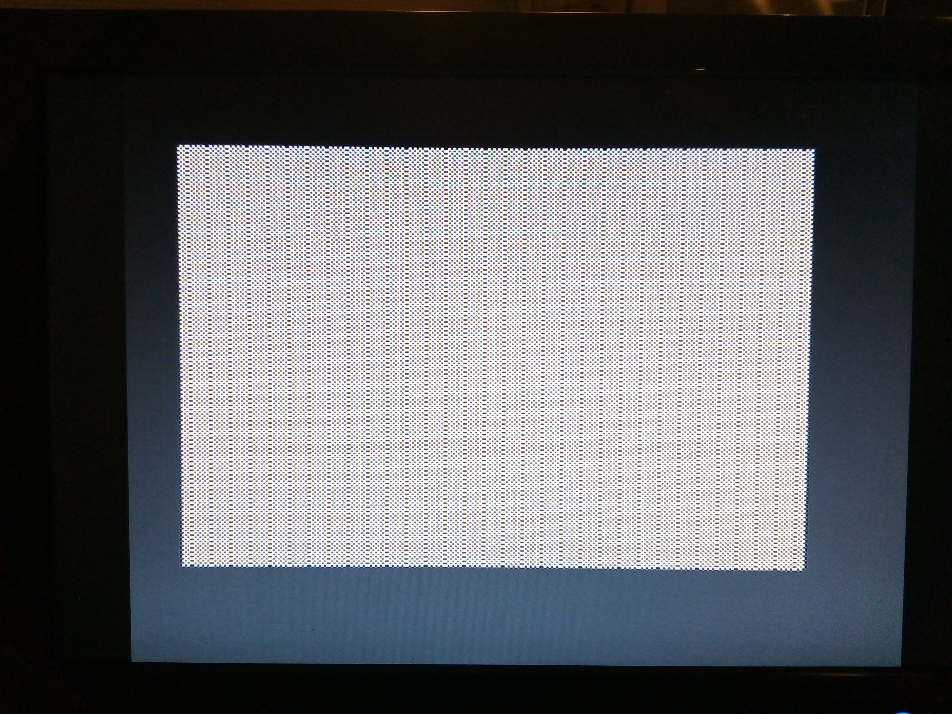
    Now I still have to check the cassette interface, attach the speaker, and solve an annoying wavy pattern in the video image, but all that will be peanuts compared to the path I've traveled so far.

  • It works.. (but only half)

    Cees Meijer11/16/2020 at 08:58 0 comments

    Th RAM adapter PCBs have arrived, and assembling was easy. So it's time for the next step. After inserting them, I switched on the power, and got this on my screen:

    Looks like the video circuit is working, but the content seems incorrect. Turns out the that Z80 does not get a clock, so the processor is not running at all. Which means that the video circuit on its own is capable of generating this pattern, which I did not expect.

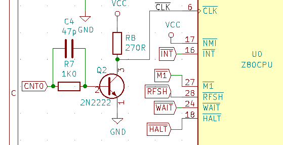
    But why is there no clock? Tracing the signal from the oscillator, it seems to stop at the base of the transistor that should buffer the signal :

    I can see the signal on the base, but there is nothing on the collector. How can ? This is the most basic transistor circuit possible, it should work ! Turns out it doesn't, because I underestimated the frequency involved. 3.5 MHz does not sound like a a high frequency these days, but it is way beyond the capacity of a 2N2222. When used as a switching transistor, the switching times go up to 250nS, which is just too slow. That's why the original Jupiter uses a 2N2369 which has switching times of 12 nS. I did not have that available, so I decide to use a BS170, a N-Channel mosfet which should be capable of switching up to 200 MHz. And that works great. Now the clock on the Z80 is square and clean.

    After switching it on again it looks like something happens. The screen is now filled with a different pattern and there are some unrecognisable blobs at the bottom row. But typing on the keyboard does change the content of the bottom row, and when pressing enter I can see the screen scroll, although the general pattern changes. The fact that it responds to the keyboard, and that this changes the screen tells me that the processor is working (after all, it is scanning the keyboard). So the problem must be in the video circuit itself, or the connections to the video RAM chips. After meticulously checking all connections from ant to the RAM, and comparing them (again) with the original schematics I found no mistakes or missing connections. Probing around with the scope however shows a lot of noise an glitches, especially around the  74HC166 shift register. Extra decoupling does not change anything, so I was thinking adding some kind of filtering to the data lines.

    Then I realised that I used all 74HC series logic on my board, while every schematic (including mine) has the 74LS series. From my past experiences I do know that the HC and LS series are definitely different. The logic (obviously) is the same, but since the HC series are all CMOS, and the LS uses low power schottky their electronic behaviour may be different. It could well be that using the 1K series resistors in the data lines may not be a good idea for HC variants.

    So I could try to solve that, or simply order a full set of 74LS chips so I can simply exchange and compare. After all, these chips are very cheap (between 0.25 and 1 Euro a piece). It only means I have to wait another week before the next test run.

    Meanwhile, while going through the Jupiter ACE section on the K? Forum I also noticed that someone else had problems with the video, which were solved after removing C8. This capacitor is there to extend, or clean up , the 'WAIT' signal. Apparently a wrong WAIT signal can delay the Z80 too long so the timing for writing to the video memory is wrong, which could cause a screen similar to what I got. Maybe worth trying, if swapping the chips does not work.

  • Inserting the Chips, testing and ... Aargh !!

    Cees Meijer11/01/2020 at 12:53 16 comments

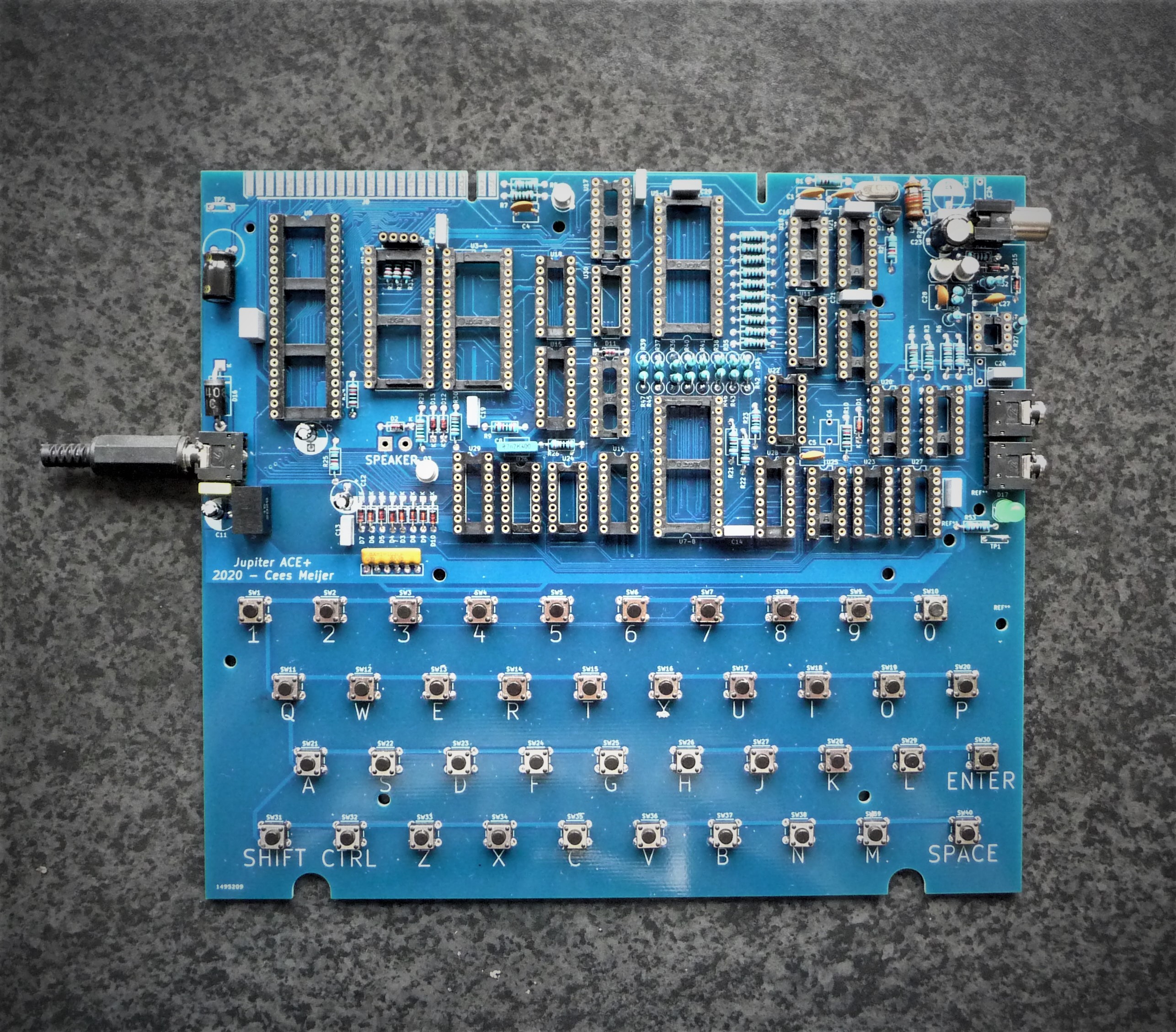
    After half a day of soldering, the board looks like this:

    Everything fits like a charm, and it really starts to look like a Jupiter ACE. So it's time to start testing, and carefully insert all chips.

    Step 1: Check what is + and - on the power connector. It turns out the Tip is ground, and the sleeve is +. Found myself a leftover power supply (12VDC/1.4A)  and mounted the 3.5 mm jack plug. Once connected the LED goes green ! This is always a good start. After that I measured the supply voltage on all main chips like the Z80 and some of the 74 series. All seems well.

    So I first mount U23 74HC86, which is part of the oscillator, so now we should the 6.5 MHz on pin 8.

    Which does not happen. There is a clear oscillator signal (with the right frequency) on pin 9, but its simply not big enough:

    The signal gets bigger if I replace R2 with  a 470K, just enough to get the signal on pin 8 going:

    Still looks a bit wacky, but I think that's also a limitation of my oscilloscope which has a maximum sampling rate of 25 MHz so there are only 4 samples per cycle.
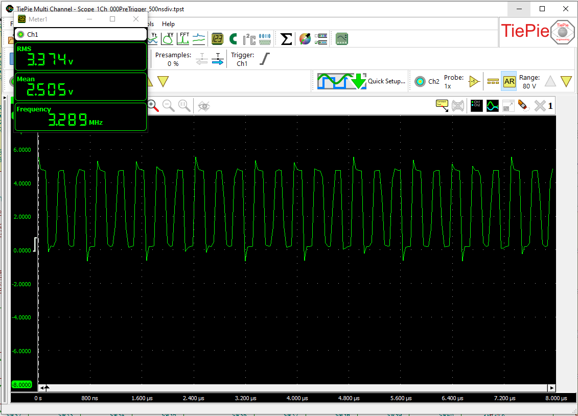
    Inserting U9: This is the clock signal divider, so there should be a clock on pin3 of U9:

    Well, at least it starts looking like a square wave now. So lets insert the next two counters, U10 and U11. Which seems to work as well, so lets mount all other chips. All good, until I came to inserting the RAM chips:
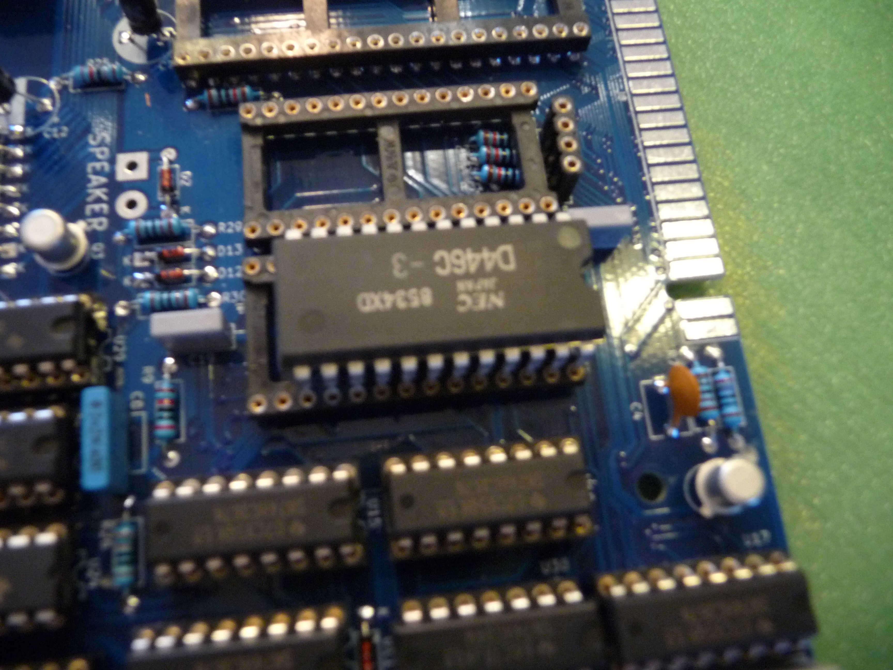
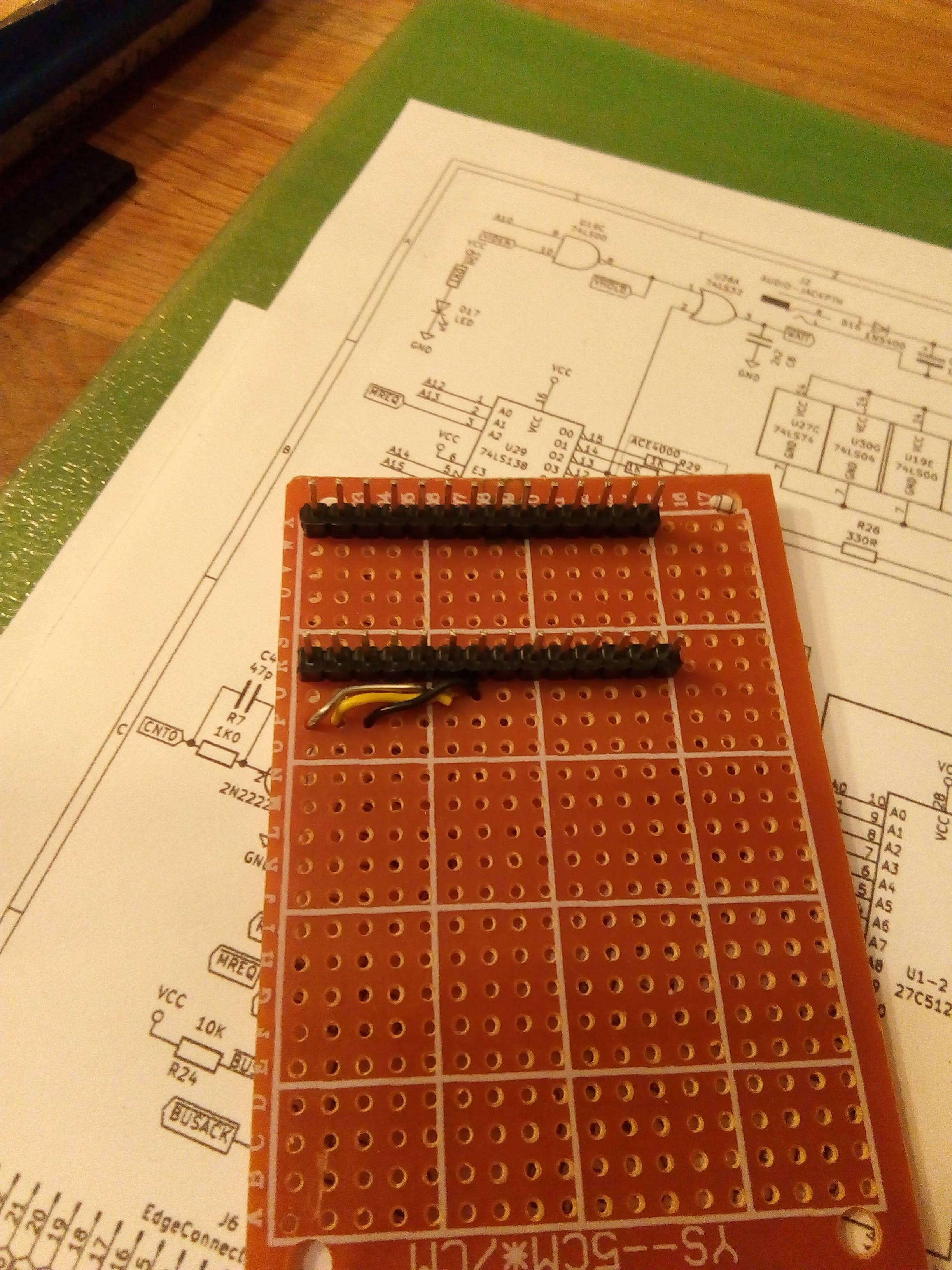
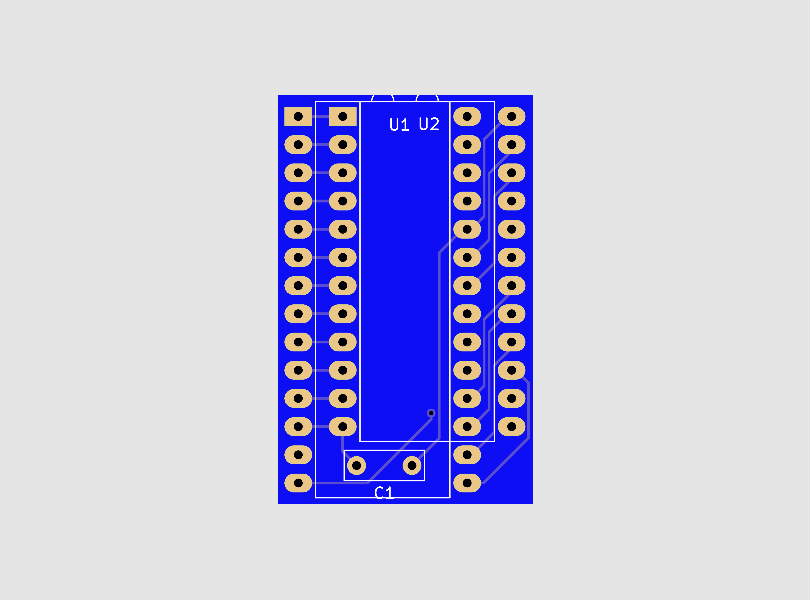
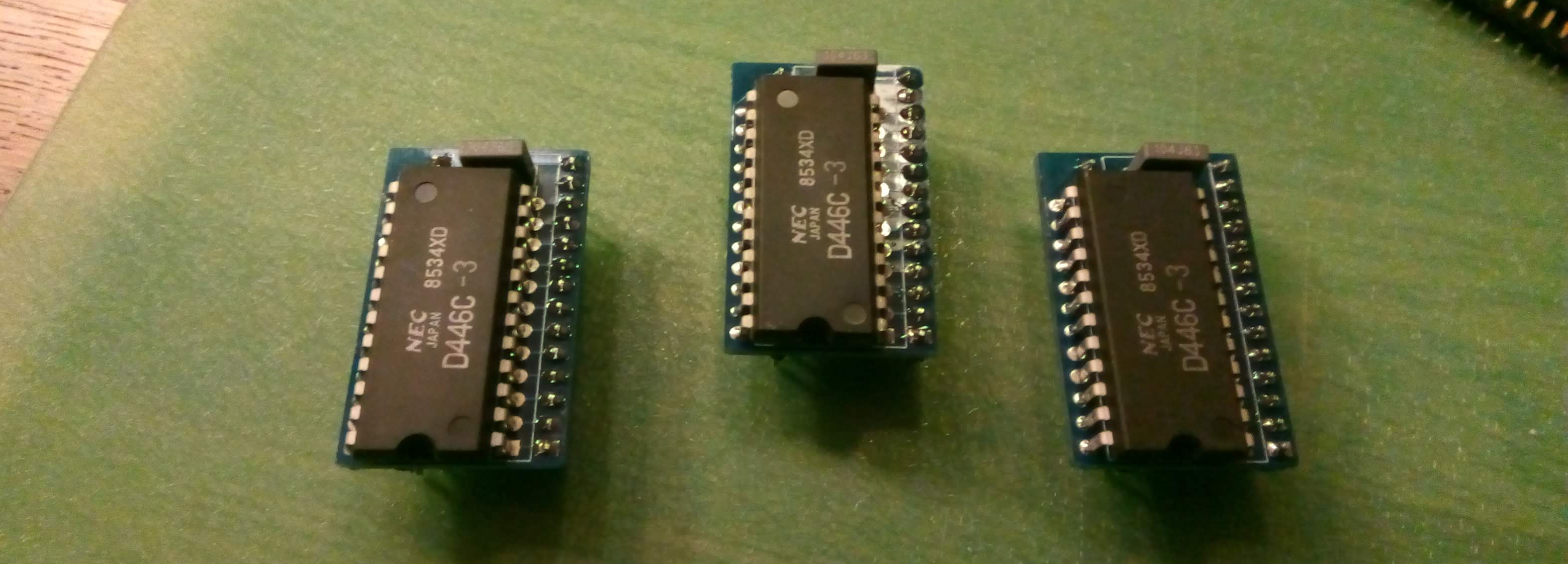
    OH NO !! The footprint is wrong. It took me about half a second to realize what was wrong: I selected the DIP28 footprint for this DIP24 chip. Not something KiCad will warn you for, after all the DIP28 has plenty of pins for a DIP24. After about  10 minute of quiet contemplation (...) I decided that I would have to make some kind of adapter with 28 pins on one side and a 24 pin socket on the other so I could re-route all pins from 12 and up.


    Good plan, but after struggling with the first four wires, and realizing I would have to do 3 adapters in total I gave up. Opened KiCad again and designed an adapter PCB in about 30 minutes. Checked with the PCB manufacturer and found that it would cost €19,- to have 15 pcs manufactured.

    So we'll have to wait another week until these boards arrive and the testing can continue.

  • The PCBs are here !

    Cees Meijer10/27/2020 at 21:02 0 comments

    This is probably the most used title on all Hackaday, since it is something that happens to most of us at a certain moment in our project.

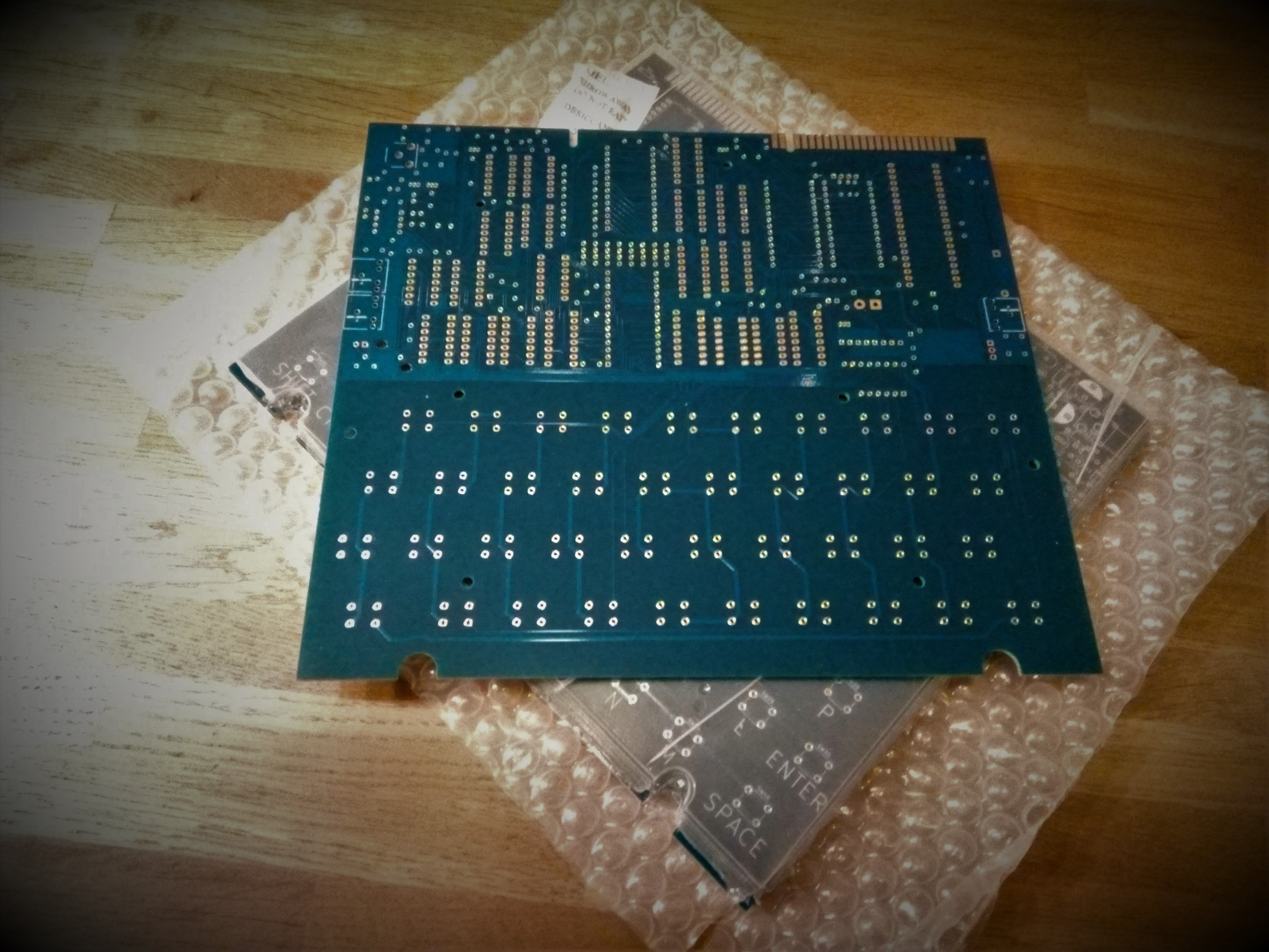
    Exactly 8 days after I sent my order, they actually arrived. And they are beautiful ! I chose the blue colour to set mine apart from all other Jupiter ACE clones. At least, that's what I thought until I realized that the Minstrel 4th is also blue, though mine have a more blue-greenish tint.

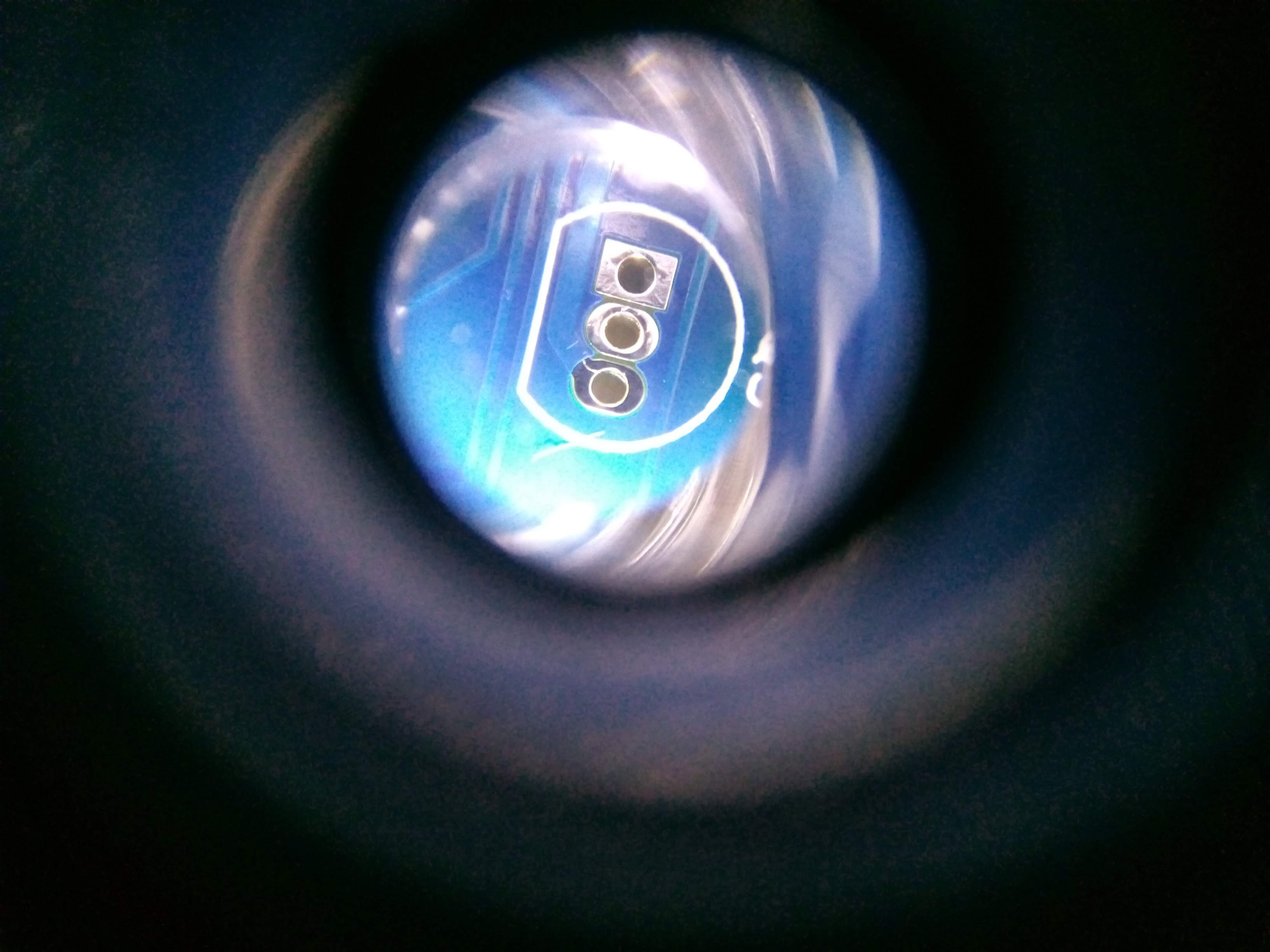
    What did struck me at first sight was how close the pads of a TO92 transistor are. I actually thought they were connected, but fortunately a continuity check shows they are not. And a very close inspection using a magnifier shows that there is indeed some separation between the pads.


    That will need some very careful soldering there.

  • The Power of Free

    Cees Meijer10/26/2020 at 20:16 1 comment

    While working on the Jupiter ACE project I was amazed, over and over again, by the power of the available free software tools.

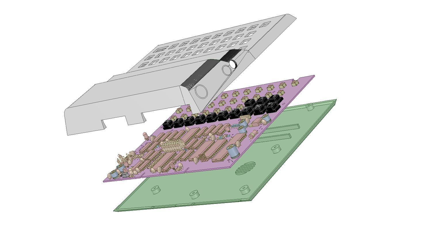
    Housing drawn in DesignSpark, PCB imported from KiCad

    First there is DesignSpark Mechnical. An extremely powerful 3D CAD program from RS Components. It's a trimmed down version of SpaceClaim Engineer, a truly high-end CAD package. Which also means it misses some features, like directly placing texts, the option to mirror 3D objects, and the possibility to export to STEP files. Which sometimes makes makes it harder to get some things done, but usually there is a workaround. It does however support import of images or photo's. Which can be place and rotated in 3D space. Something that was tremendously helpful when drawing the Housing.

    Second, of course, there is KiCAD. The free, open source, multi platform, Electronics Design package. With the release of version 5 it has really become a serious piece of software. It works flawless, and I've not seen it crash anywhere during my whole design process. The work flow has significantly improved since the previous version, and the available libraries are extensive. OK, you still cannot drag a component on your PCB while keeping the traces connected, but that's my only (minor) complaint. Tools like 3D view and STEP export on the other hand are truly amazing, and the only reason I could make an image as shown above.

    And last, the PrusaSlicer. A fork of the (already pretty good) Slic3R. Since Prusa Printers forked it, and put a (full time) team of software engineers on it it has grown to be awesome. Adaptive layering, advanced move and align tools, customizable support, 3MF project support, its got it all.

  • Final Steps

    Cees Meijer10/17/2020 at 11:32 0 comments


    Now the routing is complete, and the moment where I have to send the design in for PCB production, it's time to go over the last details.

    Decoupling capacitors
    Someone mentioned that not all chips have a decoupling capacitor, and that could lead to problems. So I went over it and placed some extra 100nF wherever there was still space.

    Silkscreen
    Next, I added the letters / figures to the keys so they would be visible on the silkscreen. I first made all text in font-size 2x2, which seemed big enough on the screen. But when I printed the board 1:1, they appeared a bit small. So I found that the KiCad PCB file format is actually text, and that it was really simple to do a search / replace action to change the font size.

    Footprints doublecheck

    Checking the few footprints I was not sure of. Especially the transistors are notoriously difficult to get right. Countless are the boards where you have to mount the transistors backwards, on the bottom or worse: with two pins crossed. I also had my doubts about the 3.5 mm connectors for power and audio, but they matched perfectly on the paper printed layout,.

    Zone fill for Vcc and GND
    Added a few more 'zone fills' for VCC and GND. So far I routed all power lines using 1mm traces, but that is not much and could possibly cause problems with the (relatively) power hungry TLL chips. So adding a bit of copper here will definitely help.

    Check the outlines
    I found that I had two board outlines drawings. The first one was the one that I drawn by hand in KiCad itself on the Edge.cut layer, and the second one is the version that I imported from the mechanical drawing (which was more accurate) on the 'Dwgs.user' layer.  So I removed all lines from the 'Edge.Cut' layer, and moved all relevant lines from the Dwgs.user layer to Edge.cut.

    Add Diode and LED
    As someone mentioned that the power plug polarity on the Jupiter ACE is different from that on the ZX80/81, I suppose its a good idea to add a diode to the power line. And then, it's always good to have a LED on the board so you can immediately see if the power is actually present.

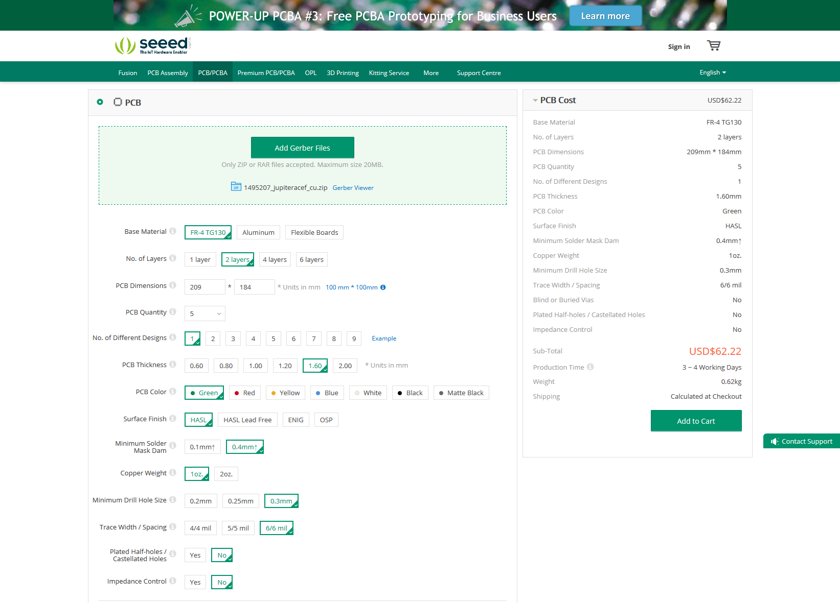
    So, finally, I think it's time to send it to China, and have some boards made. I chose Seeed Studio for that. I've used them a few times before, and the boards are always very nice. The whole process of sending the files and placing the order is described on their site, and it is super simple. And they have their own Gerber viewer, so you can quickly see exactly what the boards will look like.


    US$62 for 5 pcs. Not too bad. Unfortunately the shipment will be another US$23, so the total will be around US$85,- Still not too bad. Let's hope the board is 100%, and I might be able to sell the extra boards...

View all 22 project logs

Enjoy this project?

Share

Discussions

Jon Gratton wrote 03/15/2024 at 21:07 point

Hi, I have a question if anyone on this project has come across?

I’m pretty new to all this, but came across your project to recreate the ACE and find it so cool.

I have built up the board and came across the same issue Scott did with the white screen, removing the 555 timer for the back porch made it a black screen with the white cursor.

The issue I have is when I press any keys the cursor moves but not characters are shown.

I suspect a RAM issue, but was posting a comment in the hope you gurus may know the answer. I took some pictures, but can’t see a way of sharing unless I upload them to some cloud drive.


thanks for your time


Jon.

  Are you sure? yes | no

Jon Gratton wrote 03/20/2024 at 13:36 point

Sorted the problem if anyone ever gets the same issue of a cursor with no characters it was the 74LS166 that was at fault. Replaced with a new one and now working. The only one I had was about 30 years old out of a box of logic chips I’ve had since uni 😂.

  Are you sure? yes | no

Jon Gratton wrote 03/20/2024 at 18:06 point

outstanding now is the back porch. With the 555 timer in place I bet the same as Scott reported as just a white screen. Removing the 555 timer shows a black screen with white characters inverse.

Did the output of your findings have the same or a white screen with black characters as I see from the images you have the timer in place?

the display TV I’m using is also PAL. If I plug it into a Scart to HDMI converter I get a funky output where it just flashes on and off too even without the back porch.

  Are you sure? yes | no

Michael Gardi wrote 01/04/2024 at 14:28 point

I thought that anyone following this project would be interested in a podcast about the Jupiter Ace. It's from "Advent of Computing" which is a great podcast! 

https://adventofcomputing.com/?guid=30a474ba-6d05-47a4-a1c4-58662b0d5156

  Are you sure? yes | no

Scott Baker wrote 12/11/2023 at 03:14 point

Hello Cees.

Thank you for posting this. I managed to build one. First of all, the only technical problem I had was that it wasn't obvious to me when using a BS170 instead of 2N2369 that I need to rotate it 180 degrees. Maybe it says somewhere and I missed it, but otherwise might be useful to note in the BOM. Second, my US TV really hates the composite signal this things puts out. I'll get a flat white screen unless I hit enter a half dozen times, unplug the composite, then plug it back in. Some fellow below is talking about the back porch. Maybe that's it. I'll have to research. Third, whenever I start it, there's always some weird garbage character to the left of the input line. It's a different weird garbage character each power cycle. Maybe I need to RTFM. Other than that, it seems to work and it's really cool. I would like a version that uses Cherry MX Blue keys though. And I swear I'd add a backspace and make it pull down CTRL and 0 together.

Scott

  Are you sure? yes | no

Cees Meijer wrote 01/02/2024 at 21:42 point

Hi Scott. As you noticed I visit this page not often enough. It's only that I just came across your video on building the ACE, was surprised to see my own name on your PCB and decided to find out if you left a comment here as well.

I indeed used the 555 circuit to improve the backporch, and it was a circuit that I found online. It worked well on my (PAL) monitor. But later I did find that it would not always work on any monitor. Never found the time to really dive into this.

To me it's really funny to see all the things you tried to fix the character generation. My initial design did not work either, and I also did the HCT to LS chip swap, added capacitors etc. It turned out to be an incorrect routing in the end, and it looks like I was lucky with all the rest.

Good you have not tried to use the tape interface to load your programs, I never actually got that working either. Also I never used the edge connector for anything so its good to see it works. 

Regarding the keys: It was my intention to modify it later to use 'silent' keys, but that has not happened yet.

Now I'll probably have to build your Raspberry Pi expansion and memory board. Thank for the great video, I'll add a link to it here.

  Are you sure? yes | no

Scott Baker wrote 01/03/2024 at 02:54 point

Thanks for the response! Composite video is sometimes a bit of a mystery to me. Maybe I should take a look at the NTSC specification and see if I can figure out what the issue is.

Do you have the specific part number and manufacturer on the SRAM ICs that you used? Would be good to compare against mine and see if there is one that just happens to work without modification.

The edge connector did work great -- I was pleased that the expansion boards all worked without issue. I'll have to look at the tape and see if I can reproduce the same issue that you did. AS of yet, I haven't even soldered the jacks to the board for the tape. My Pi Supervisor board can load .TAP and .ACE files into memory, and it should be relatively easy if we wanted to make it be able to save them from memory to a .TAP or .ACE file as well. These file formats were both well documented.

Thanks again for all your work on this project, and especially the debugging info above.

  Are you sure? yes | no

Cees Meijer wrote 01/03/2024 at 20:18 point

I just checked the SRAM chips. I used both the NEC D446C-3 and the Hitachi HM6116P-70. The HM6116 are used at U5 and U7.

  Are you sure? yes | no

Thomas wrote 07/17/2023 at 03:34 point

Hi Cees,

I wanted to build your project because it's really cool, but I have a few questions first if you don't mind. I'm currently making up a BOM for Mouser to make ordering the project easier for myself (and hopefully others in the future).

First, I was wondering if you can please provide gerber files or update the KiCad files for v7. I'm not experienced with PCB design but I'm trying to figure it out myself (though most seem fairly straight-forward fixes, from what I can tell). Even with KiCad 5, I get come "Courtyard Overlaps" errors when running a check, but I'm not sure if that's an acceptable problem or not.

In regards to the CPU, I assume the Z84C0008PEG is the best modern choice. I'm not sure if the Z84C0006PEG is enough (from what I understand, it'll be clocked down to just over 3MHz via the crystal so maybe the 6MHz Z80 is more than fine, but I'm not sure if the value is halved like how the crystal is).

ROM-wise, is a 512k ROM needed, or will a 64k chip work? Maybe I missed it but I didn't see you mention the ROM anywhere, other than some comments mentioning using a 64k ROM but swapping to (unlabelled/undocumented) jumpers instead.
Grant has it on his website and it's only 64k/8K, so I'm not sure why a bigger chip is necessary (availability, of course, since I don't believe 27C64s are made any more, but 27C128s are, I believe, so I'm not sure why you chose the biggest one - maybe there's a good reason of which I'm unaware).

In the BOM, you have 1K0 and 1K resistors of the same dimensions - as far as I'm aware, these are the same value, so shouldn't it just be 20x 1K?
I don't have the PCBs yet so I'm not sure if it's even worthwhile having the different dimensions instead of just getting one set of each duplicate value (1K and 10K) to use for all of them.
Also, is there a reason you wrote 56E and 68E instead of using R like the others? Just thought that might be less confusing.

It seems the original BOM had 2 1Kx8 resistor networks, so perhaps this one should be 16K?
You said it doesn't matter as long as it's between 1K to 47K, but it'd be nice to standardise a value if only for an orderable BOM.
Same for L1 - do the specifics such as the Max DC Current and Max DC resistance matter at all? If not, the cheapest Bourns RF inductor (77F102J-TR-RC) seems like a good choice.

RAM-wise, I'm not sure what modern RAM chips to use.
I'm not sure if this is where an adapter board is required (if so, can you provide gerbers please?), or if there's a modern drop-in replacement I can use without having to source second-hand or new old stock parts.
It seems you changed the PCB at one point to take DIP-24s instead of DIP-28s, so maybe this is a non-issue now, but the only modern chip currently available matching the specs you used (2k x 8) is the rather expensive Renesas 6116SA120DB.
I designed an adapter board for the cheaper SOIC-24 variants but I'm not sure if the far lower latency (about 10x faster) will be an issue.

How much RAM can the PCB take? You're using more than the original layout (1K x 4 per chip, if I'm not mistaken), but can even bigger (and thus cheaper) chips be used?
The original could be expanded up to 49K officially - is it possible to use more on this board or would an expansion be needed like the original? I figure I may as well max out the RAM if possible, after all.

For the switches, how did you mount the 2-pin SMD switches to the 4-pin footprint? They seem like the best option for something relatively soft, but the PCB footprint definitely isn't right. It's a shame there appear to be no through-hole versions of those switches available (I did spend a while looking to be sure).

One last thing: what is the most accurate version of the case model you have available that actually fits this PCB? You mentioned Alejandro's version but it seems like it's not a perfect fit for this PCB. I don't mind if it's not super-accurate (though that we be a bonus), but I thought the version you provided was the "less accurate" version, so I just wanted to check which one I should be printing.


Sorry for all the questions. Thanks so much for your time and the project though.

  Are you sure? yes | no

Cees Meijer wrote 01/02/2024 at 22:01 point

Hi Thomas. Sorry, it seems like completely missed this post at the time, and I'm not visiting this site often enough to notice. I'd still be happy to answer all your questions, but I can imagine you already found some answers yourself ( if you haven't finished the build already... ) Please let me know, and I'll get back to you. ( You can also email me: cees.meijer65 AT gmail.com )

  Are you sure? yes | no

Ronivon Costa wrote 10/25/2022 at 07:46 point

HI Cees.
This is a really complete project, amazing work you have done. I am amazed, really, even so by the case in 3D print. I am considering buy a 3D print just because of that.
Regarding the PCB design, you looks great as well.
 I tried to quickly import into my KiCad 6 app, and after I ran some checks in the PCB traces, I got around 37 errors, mostly overlaps.
I inspected, and it really looks like there are overlaps.
I wonder if that was because I imported it into KiCad 6 - which version did you use?

Thanks for this great work. I will try to build it if I get all the clearances errors cleaned up in KiCad.

  Are you sure? yes | no

Ken Yap wrote 10/25/2022 at 10:40 point

I think Cees started the project before v6 was released. If you had to do an import then he did it with v5. You're lucky only clearances are involved. Do feed back the updated project to Cees.

  Are you sure? yes | no

Cees Meijer wrote 10/25/2022 at 11:47 point

Thanks for the praise. Glad you like it, and I always find it exciting when other people decide to build it too. If you finish it I'd love to see the results.
Regarding the import in KiCad 6: I think this probably causes the issues that you see. I did the whole project in version 5. I did try 6 as well, last year, but soon found that most of my designs had issues after importing them so I reverted to 5 again.

  Are you sure? yes | no

emiliano.lenticchia wrote 10/31/2021 at 20:54 point

Hi, I'm new to ACE things but this is a great project, I think... I wish to build my own ACE but I cannot make PCB  form KiCad files (old machine, old version, various error)... Its possible to have the corrected gerber of this?... Thanks

  Are you sure? yes | no

Frits Jalvingh wrote 09/14/2021 at 13:33 point

Hi Cees, thanks a lot for this great project! I ordered the PCBs and have built it with some minor changes. Most of it seems to work with the exception of video 8-/: the screen does not seem to sync correctly. You can see that it contains characters (and the keyboard adds characters). I will still have to do some debugging there..

  Are you sure? yes | no

cuvtixo wrote 05/26/2021 at 23:11 point

I appreciate the work, but I dislike the introduction blaming Forth for poor sales. Sales were much too poor to be explained by lack of BASIC alone. The graphic from Buyers Guide Home Computing Weekly 8th November 1983 on https://jupiter-ace.co.uk/reviews_BuyersGuide-HCW.html Shows the ZX81 selling for £39, the Aquarius computer at £59.95 and the Jupiter Ace  £89.95. THAT was probably the biggest reason, especially considering the Jupiter Ace had very similar hardware capabilities. Also, the vast majority of reports of 8-bit BASIC programming I've heard, were failed attempts at hand typing programmes from small computer magazines. I doubt with so much frustration from users at writing much of anything in BASIC, that Forth would make much difference to any buyers. There were only 800 "Jupiter 4000s" made for the American market, but likewise we can't blame any particular features or lack thereof for doing poorly in America. It didn't have nearly enough distribution there before the company went bankrupt. Being undercut by the competition by more than 50% tends to have a negative effect on sales. (take previous understatement with appropriate snark). Although I'm curious, Cees Meijer, whatever inspired you to blame Forth (or lack of BASIC)? 

  Are you sure? yes | no

Cees Meijer wrote 05/27/2021 at 06:50 point

Wow, what an in-depth analysis... I have read a lot about the history of Jupiter Cantab since I started this project (and wrote the intro) and you are right. The failing of the ACE is not just caused by the FORTH language. Pricing, marketing, production planning and just shear bad-luck also played a huge part in it's demise. Nevertheless, FORTH did not help. If 99% of all magazine listings and books focus on BASIC, it becomes the default standard. And now I have built my ACE and made the first attempts to write some programs, I must confess it's definitely much harder to get started than with any BASIC I have ever used.

  Are you sure? yes | no

cuvtixo wrote 05/27/2021 at 20:22 point

From a user perspective, certainly. It reminds me of the Atari2600 E.T. game. It didn't bring down the entire industry in the US by itself, but a spectacularly promoted, awful, pre-maturely released game epitomized a lot that was going wrong on the Atari business side, also. I'm more of a history buff than a programmer. I found Basic (on the Apple II, specifically) to be so frustrating I gave up on programming. Another motivation for me not wanting to see it credited for success of anything.

  Are you sure? yes | no

James wrote 03/15/2021 at 17:45 point

Great project - thanks for all your hard work.

Please note the gerber files on your seeedstudio page are still the "old" version with the wrong RAM footprint, and probably the other 2 errors. https://www.seeedstudio.com/Jupiter-ACE+-g-1308251

Don't ask me how I know... (grrrrrr!)

  Are you sure? yes | no

Cees Meijer wrote 03/16/2021 at 07:22 point

Ah, damn. I completely forgot I made these public on the Seeed studio site as well. I'm very sorry if you ordered these.. I'll remove them right now.
If it helps, I still have a set of RAM adapter-boards available, which I can send you so you can at least complete one board ?


(Update: I've tried to remove the board from the Seeed gallery, but I have not found a way to do so. Actually I cannot even find it through my account, only by clicking the link that you sent me. I don't think I'll ever publish a PCB again..)

  Are you sure? yes | no

James wrote 03/16/2021 at 13:47 point

Thanks for the quick reply.

It's a pity the seeedstudio site does not allow commenting. You may have to contact Support on the site to get it removed.

The funny thing is that I had the gerbers from this hackaday project (the KiCAD files), but I decided to use the gerbers on the seeedstudio site anyway, I guess I thought they were "known working" files or something. Anyway I've learnt my lesson :)

Don't worry about the RAM adapter boards, I've already started making my own.

Are there any other issues / bugs with the "old" version of the board that I need to know about (besides the 3 errors you have mentioned in this hackaday project already)?

  Are you sure? yes | no

Cees Meijer wrote 03/16/2021 at 15:01 point

I contacted Seed Studio support, and they alread removed it, so that cannot happen again.
And I think I only mentioned 2 of the three problems in my project blog. You already found the RAM error and the incorrect /CS connection, I assume. But the third one is a trace between U9-1 and R8. That one should be cut, or the Clock will not work.

I also have not got round to testing the Tape I/O so there could be issues there too, but that can only be changing parts values.

  Are you sure? yes | no

James wrote 04/02/2021 at 08:10 point

I've now soldered up the "right" version of your PCB (the KiCad one attached to this hackaday project), I have 2 questions:

1. What is the value of inductor L1 ? Can it be bypassed with a jumper wire?

2. What is the correct value fo resistor R1 ? Your schematic says 47k, but the original schematic (and other schematics I've seen), says 4k7 (4.7k).

The soldering took probably 5 or 6 hours total. The only difficult bit was soldering the transistors as the pads are very close together.

Can't wait to power it up (and then probably debug some issue :) . Just waiting on the 6.5Mhz crystal which is coming tomorrow.

  Are you sure? yes | no

Cees Meijer wrote 04/02/2021 at 19:09 point

Hi James. First let me tell you that i'm really excited about the fact that somebody is actually building my version of the ACE. Though I could have expected it since I posted it all here, it still comes as a total surprise. I really hope you can get it working, and I'd love to see some photo's and hear about your experience during the build. The transistor pads are indeed a bit worrying, yet I already soldered two PCBs and it never raised a problem. I even replaced one, and it still worked. It's a good test for your soldering skills ;-)

Regarding your questions:
- I used a 1mH inductor, since that's what I had in stock. Any value near that or higher will do.

- The resistor value is an interesting one. I took the 47K from the schematic by Bodo Wenzel, but when looking at the scan of the original schematic I see it is indeed 4K7
The 47K works for me, but I had to increase the value of R2 to 100K to get enough output from the oscillator. I suppose it also depends on the model of the crystal and which type of 7486 you use.

Good luck with the last steps, and fingers crossed for tomorrow...

  Are you sure? yes | no

James wrote 04/10/2021 at 14:18 point

Well I finally got it working today :)  (I had to first build an adapter for the one RAM chip as I only had 2 6116).

On first power on (with just video circuit chips), the clock circuit worked fine (as per the schematic). However nothing on the monitor screen. I found I got a reasonable video signal from D14, but no/bad signal after C24/C25.

With all the chips inserted, and power on, there was no clock on the CPU. After a bit of probing and thinking, I replaced R7 with 680 ohms resistor to get the voltage coming in to base of Q2 (2N2369) above the 0.6? V needed to switch (?). This seemed to work, so I now get "OK" if I press enter and can do VLIST.  (Note I did not do any transistor calculations here, and I don't know if there are any bad side-effects of this change).

All logic chips are 74LS.

I did not have a 1N5400 diode so I used a 1N5408 for the power input reverse polarity protection (not sure this will work?).

Total soldering time was approx 5-6 hours. Then another 5 or 6 hours making power adapter, ram adapter and probing/debugging.

Other things I noticed:

1. 7805 regulator gets very hot with the small heat-sink I have, definately needs a heat sink the size of the original ACE.

2. There are 2 R27 on the board. The one is just to the right of the 555 (and is on the schematic), the other is just below the video connector (and is not on the schematic). I did not solder in the R27 below the video connector. Is it required?

Link to images: https://drive.google.com/drive/folders/1eHxwiI8ZIOoOV_FggC21jO4Pvu2Me9T3?usp=sharing

  Are you sure? yes | no

Cees Meijer wrote 04/10/2021 at 15:15 point

Hi James. This is really great. I just looked at the photo's, and they look very familiar.. As you probably read in my logs, I had some trouble with the transistor too. And going from 1K to 680 Ohm is not a problem.

You're right about the 7805 regulator. I actually used a Traco Power TSR 1-2450 switching regulator to avoid this.

The 1N5408 is fine, this just has a higher voltage rating.
And last: I have no idea where this 'orphaned' R27 comes from. Must be a leftover from an earlier design change. I see I mounted it as well on my boards, and does not seem to do any harm, but it may not be necessary either.

  Are you sure? yes | no

Michael Gardi wrote 05/23/2020 at 13:33 point

I know this is late in the game, but your keycaps could have been printed in 2 colors if your printer supports the ability to change filaments at a specific layer height.  I've used this to great effect in a number of my projects.

  Are you sure? yes | no

Cees Meijer wrote 05/23/2020 at 14:31 point

Could be an option. It would indeed just require 1 filament change at a specific hight so it should be doable. It's something I have not done before but definitely worth trying.

  Are you sure? yes | no

Michael Gardi wrote 05/23/2020 at 15:03 point

If you printer supports it it’s pretty easy to do. The Plug  Panel on my H-500 was done that way. 

  Are you sure? yes | no

Alexander R Pruss wrote 10/11/2020 at 14:42 point

Do you actually need any special printer support? Can't you just add a pause command to the gcode? I guess doing it for a lot of keys might call for some automation, like my python script (e.g., https://github.com/arpruss/miscellaneous-scad/blob/master/scripts/insert.py ).

  Are you sure? yes | no

Michael Gardi wrote 10/11/2020 at 15:16 point

You are right. All my slicer does is add a special pause code to which the Prusa will not only pause, but prompt to unload the current filament then prompt to load the new filament before proceeding. If you can switch filaments when paused on your printer you  can use this technique. 

  Are you sure? yes | no

Cees Meijer wrote 10/11/2020 at 20:23 point

I think that if I print all the keys at the same time, I only need a single pause to switch the filament since all 'white text' will start at exactly the same layer.

  Are you sure? yes | no

programmez wrote 02/15/2020 at 14:30 point

Have to create 2x4k rom ?

  Are you sure? yes | no

sjkelly36h wrote 09/05/2019 at 23:30 point

I would just like to wish you good luck with your interesting project.

Having looked at Grant Searle's projects, I was thinking of doing something similar, but unfortunately my skills are less than my enthusiasm at present.  

Then I saw your project.  If I can get one of the Chinese fabs to make me a decent pcb from your gerbers, then a new Ace becomes more of a possibility for me.

I had an original Ace back in the day and my recollections are that you couldn't do much with one without the RAM pack.  Have you considered adding a RAM expansion to your PCB design?  The Ace wasn't a sturdy unit and the keyboard wasn't very good.  Many times I remember pressing the keys a bit too hard, wobbling the RAM pack and resetting the machine.

That really is an original feature I could personally do without!

If this is of interest to you, there is a two chip design for a 96k ram expansion at https://www.jupiter-ace.co.uk/hardware_96kram_pack.html 

Obviously, it's your decision, but adding this to the pcb wouldn't detract too much from the originality IMHO.  It would give you a much more usable device, though.

Please keep up the good work.

I will continue to follow your project with much interest.

  Are you sure? yes | no

Cees Meijer wrote 09/06/2019 at 08:17 point

Thanks for your comment, and great to see you are actually considering building one yourself. As I am (very slowly) approaching the end of the routing process, there is not much left for changing the design. The RAM pack is indeed a interesting addition, but there certainly won't be room on the PCB to have that included.

The keyboard will hopefully be slightly better than the original. I have already done some tests using the miniswitches and 3D-printed keys, and it seems to work well. You still won't be able to write a novel on it, but it's an improvement.

Once I finished the PCB, I'll have a few made in China. Then I will of course test it first, but if it's OK, I will probably sell the remaining boards. Which then could be your chance to get one. But I will of course publish the final Gerbers here on Hackaday, so feel free to order your own. And with all the KiCad design files available as well you might even want to add some modifications of your own.

  Are you sure? yes | no

danjovic wrote 07/27/2019 at 14:45 point

Nice work you have been done so far! If you please allow me suggest you a couple of improvements:

# 60Hz support. It might require an extra 7400 and some solder jumpers 

# Backporch for video signal, which will also provide a signal that best matches voltage and output impedance of rs170 (ntsc) video. Backporch itself is not necessary with white characters ovet black background, but the impedance/voltage matching is just a matter of using three calculated resistors instead of the output transistor.

I can make some drawings and post them on a page after this weekend, and then you can look at that and see if my suggestions worth the effort...

  Are you sure? yes | no

Cees Meijer wrote 08/06/2019 at 07:10 point

Thanks for the comments. Just returned from my holidays so I only just saw them.

I considered 60Hz support, but I'm not sure if that is still required. I suppose most modern display devices do not have any problems with 50 or 60 Hz. But I could be wrong.

I read about the 'backporch' issue but never really understood it. Could be due to my 'European / 50 Hz / PAL ' view of the world. But if you can send be some drawings I'd be most happy to integrate them. I have only just started the actual routing so there is still plenty of time to incorporate some changes.

  Are you sure? yes | no

danjovic wrote 08/06/2019 at 22:16 point

You welcome! 

Backporch is necessary for the TVs to correctly detect the relative amplitude of the video signals. It consists of a period of time right after the sync tip when the amplitude of the video signal should be equal to the blank level. 
If you have white charactes over black background it will not be an issue, as the video signal will be normally black during backporch period.

To generate the backporch you can use a RC network that lingers the SYNC pulse and then use the "elongated" signal to blank the video signal. Using this principle you can take the links [1] and [2] as a reference to design the backporch circuit using spare gates.

The impedance/amplitude matching can be done with a bit of math considering the state of Sync and Video for the moments of SYNC TIP, VIDEO DARK, VIDEO WHITE for both open circuit and under 75 ohms load. The best part is that your backend video circuit consists of only 3 resistors. Please take a look at link [3]

[1] http://danjovic.blogspot.com/2015/07/tk85av-tetraloaded-corrigido.html
[2] https://hackaday.io/page/6345-backporch-for-zx97-lite
[3] https://hackaday.io/page/2434-generating-video-signals-on-a-microcontroller-with-correct-amplitude-and-impedance

  Are you sure? yes | no

Cees Meijer wrote 08/07/2019 at 20:11 point

Thanks again for your suggestions. I've just read all the info in your links, and it is an excellent explanation of the video signal generation. I'll certainly use this in my schematic.

  Are you sure? yes | no

johntkennedy wrote 06/21/2019 at 17:46 point

Oh, and check out "Forth Programming" - they republished the original manual a year or so ago, and it's on Amazon!

  Are you sure? yes | no

Cees Meijer wrote 06/24/2019 at 07:19 point

Yes, I've seen that. Haven't bought it (yet).

  Are you sure? yes | no

johntkennedy wrote 06/21/2019 at 17:45 point

I did have an Ace - it was cheaper than the Spectrums my friends had - and different. The build quality was awful but using FORTH was a really interesting thing to do. I'd love to create it (preferably with HDMI and a SD storage card) :-)

  Are you sure? yes | no

Cees Meijer wrote 06/24/2019 at 07:22 point

Nice! You have the first version with the vacuform housing) or the 'ACE4000' model ?

As I am aiming for staying close to the original as much as possibe, there will not be a SD card or HDMI output, but I will include a standard Video output.

  Are you sure? yes | no

johntkennedy wrote 08/12/2019 at 04:22 point

The original "vacuform" aka yoghurt pot plastic :-)

How's your progress?

  Are you sure? yes | no

Cees Meijer wrote 08/12/2019 at 06:48 point

Well,  holidays got in the way, so progress has been slow for the past month. Still working on routing the PCB. Which, since I wanted to do it manually, is quite a lot of work.

  Are you sure? yes | no

Ken Yap wrote 06/05/2019 at 08:06 point

Nice that you're bringing this to life again. I remember seeing ads for this when I was in the UK in 82. I mentioned it to a friend of mine and he may have bought one, I seen to remember him complaining about the Chiclet keys; I'll have to ask him next time we meet. I admired Forth for what it could do with little resources as microprocessors were all I could afford, not Unix workstations like at work, but never got around to using it. I think I don't have enough brain cells left now to program in Forth, hahaha.

  Are you sure? yes | no

Cees Meijer wrote 06/05/2019 at 08:20 point

My experiences are similar. I also saw the ads, but never had one. And I'm not sure about my Forth capabilities either, but I expect it will take quite some time before I get to the actual programming....

  Are you sure? yes | no

Similar Projects

Does this project spark your interest?

Become a member to follow this project and never miss any updates