smartroad
-
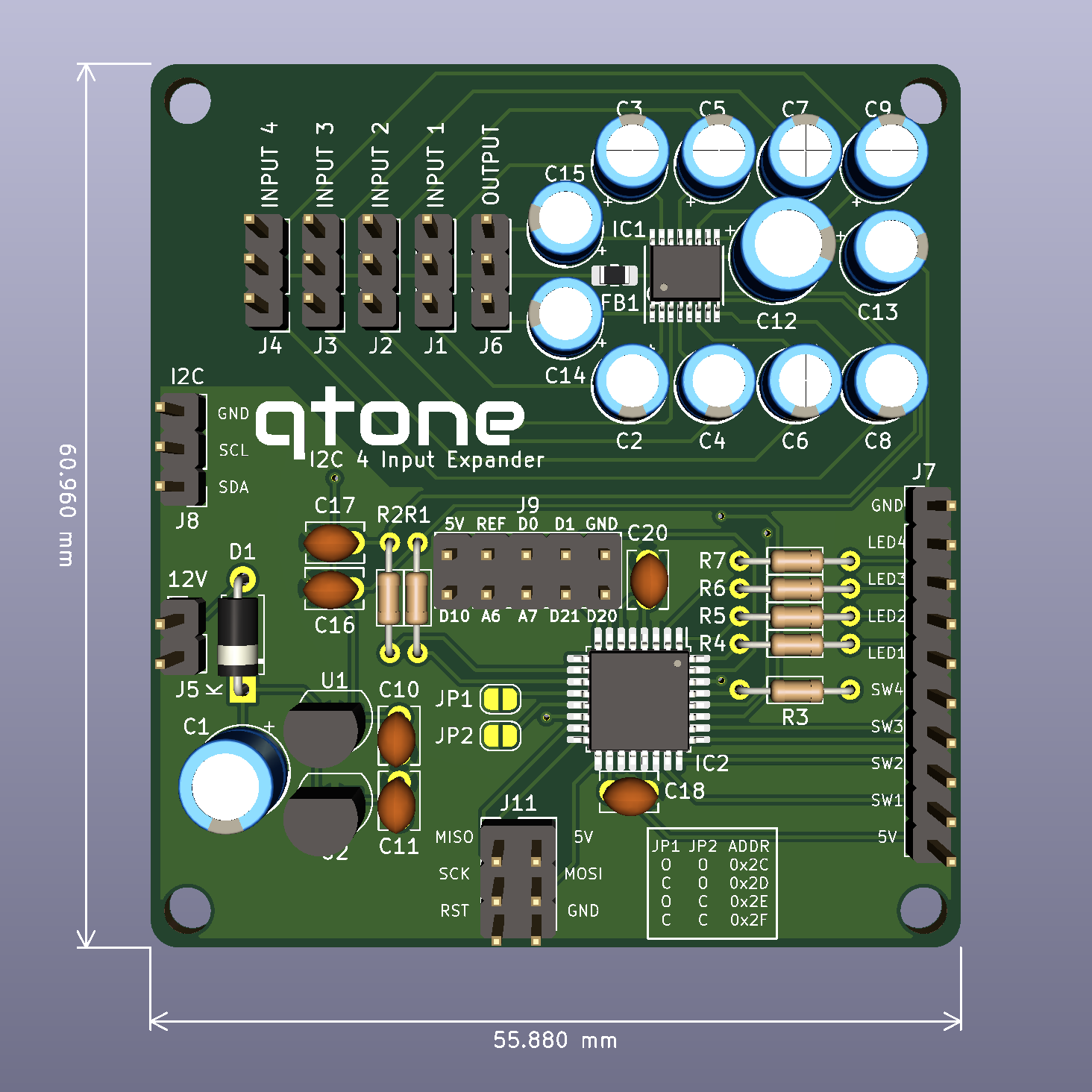
PCB Update - "J9" header
06/19/2020 at 11:19 • 0 commentsSince completing the PCB and building the first version I have further updated the circuit. For some reason I had put in the crystal oscillator for the ATMEGA. I have no idea why because it was always going to be driven by the internal RC oscillator, mostly as it doesn't have any specific need to accurate timing and the I2C bus is clocked so again is independent of the ATMEGA's clock. I am using MCUdude's MiniCore and with the RC OSC in use the XTAL pins can become additional IO pins.
With the removal of the crystal an amount of board real-estate was freed and I have used that space to implement the "J9" connector. This connector simply connects to the unused pins, D0, D1, D10, D20, D21, [A]REF, A6 and A7 and breaks them out for any other uses. D0 and D1 are the UART pins, although given the internal OSC probably not that reliable in that mode. There seems to be no ham in bringing them out and someone might find a use for them as well.
As a side note for anyone who doesn't know, the A6 and A7 pins are analogue input exclusive so can not be used as digital IO.
![]()
-
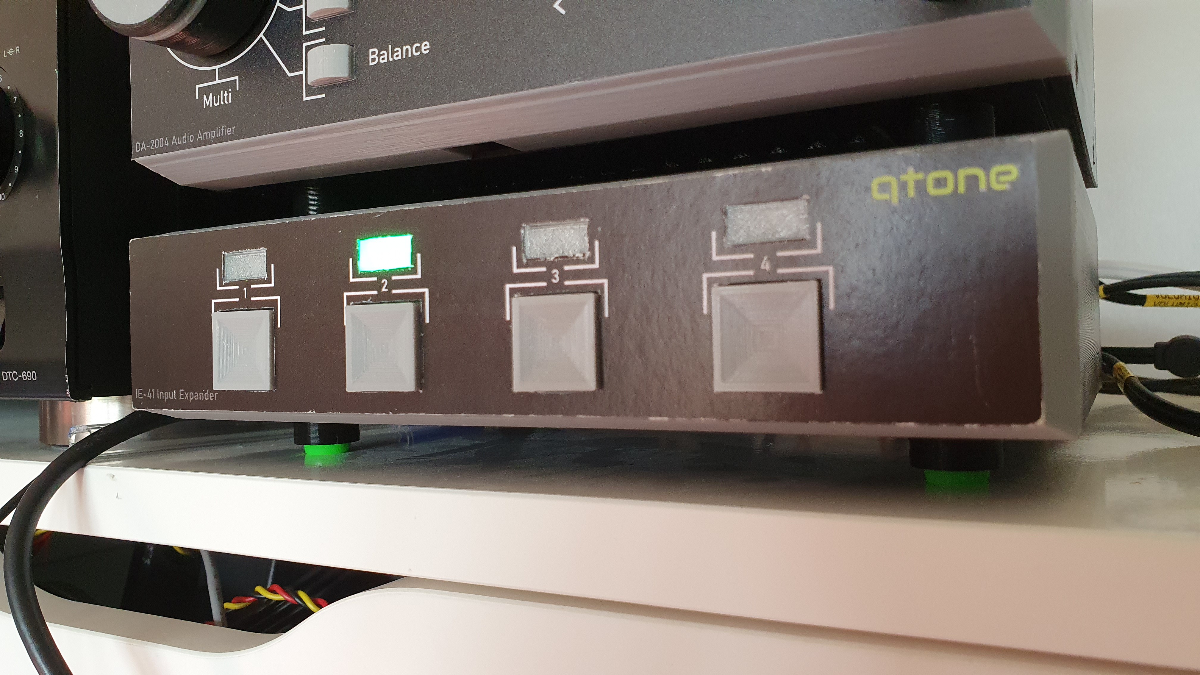
Finally Working!
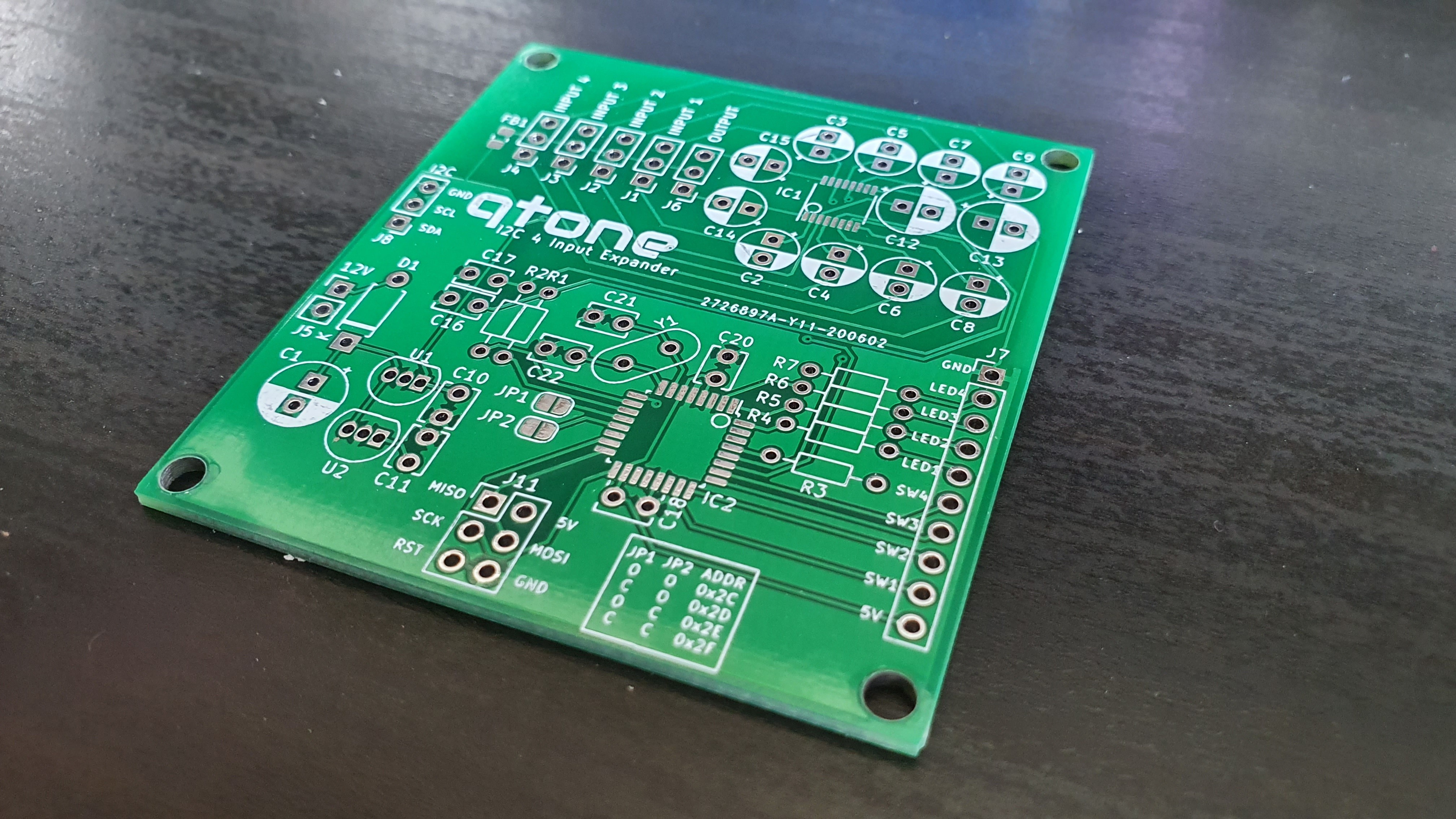
06/15/2020 at 17:36 • 0 commentsFinally I have got the new circuit designed and the PCB has arrived! Here is the board:
![]()
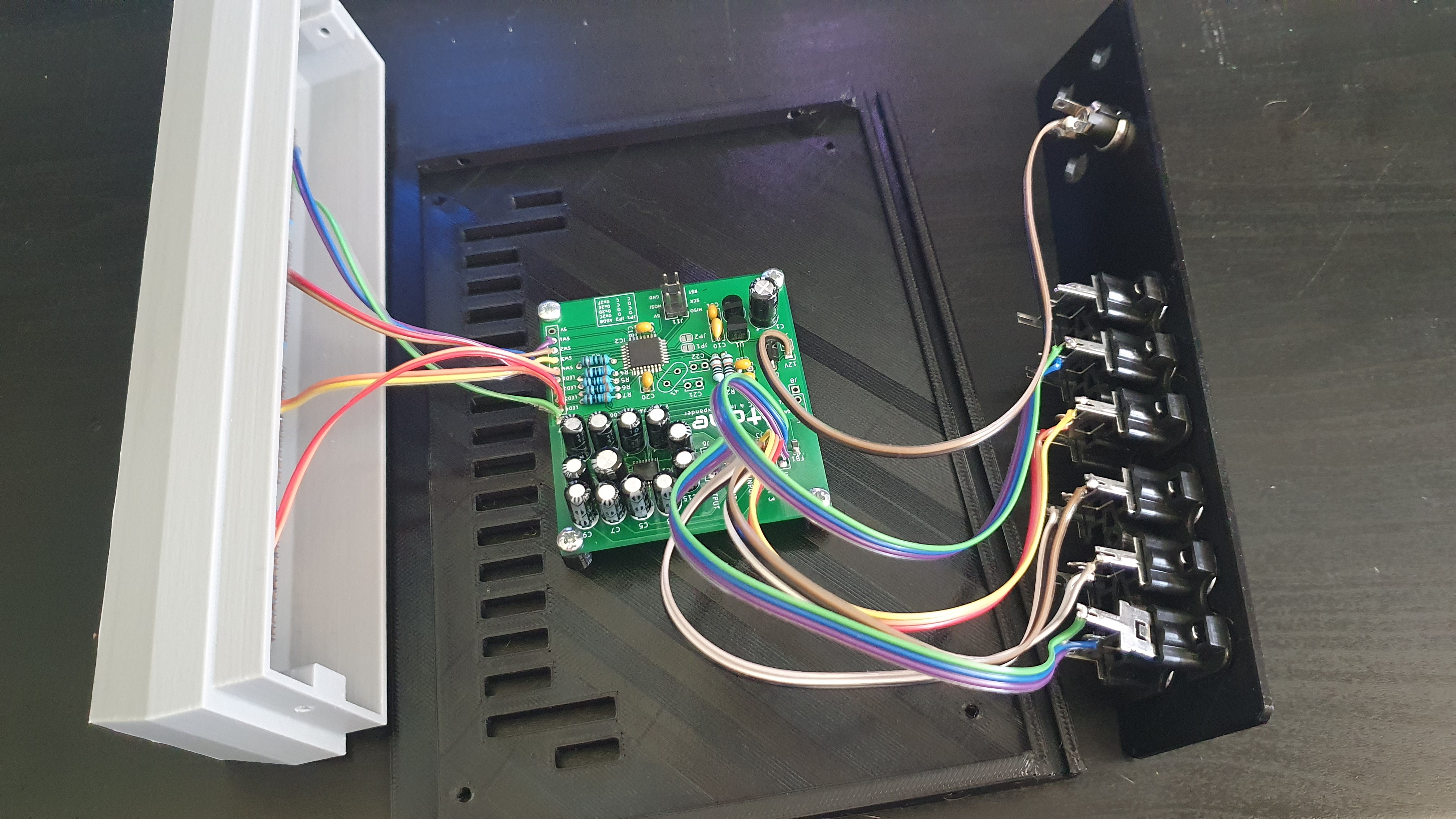
And it built:
![]()
Finally it works! The unit is able to take the push buttons on the front and select the right input. I have also used 6x2 phono connectors rather than individual connectors as I have used on my amplifier. These are cheap versions and you can see that the 1st port (the output) has fallen out. You can see a small tang that needed to be pushed 'up' for it to lock in correctly. Not seen in the above photo is the second power connector and the I2C connector (a 3.5mm stereo jack). The I2C port allows the unit to be controlled from the amplifier as well.
You may notice that the crystal (and associated capacitors) are missing. This is a cost saving exercise as the ATMEGA doesn't need the timing precision to do it's job. My original idea was to use the internal RC oscillator so not sure why I put the crystal on there!
![]()
I'll see about getting the new PCB and Arduino code uploaded soon.
-
New circuit design and PCB on order
06/03/2020 at 14:44 • 0 commentsI ordered the old PCB and it really didn't work. I didn't need the adjustable resistors as the issue they were there to resolve was actually a programming error on my amp (doh!). I think accommodating those caused issue with the audio signals so it just didn't work.
The new circuit design has been implemented and ordered so hopefully this one will work correctly. I will update once I have them in hand!