 Malte Schrader
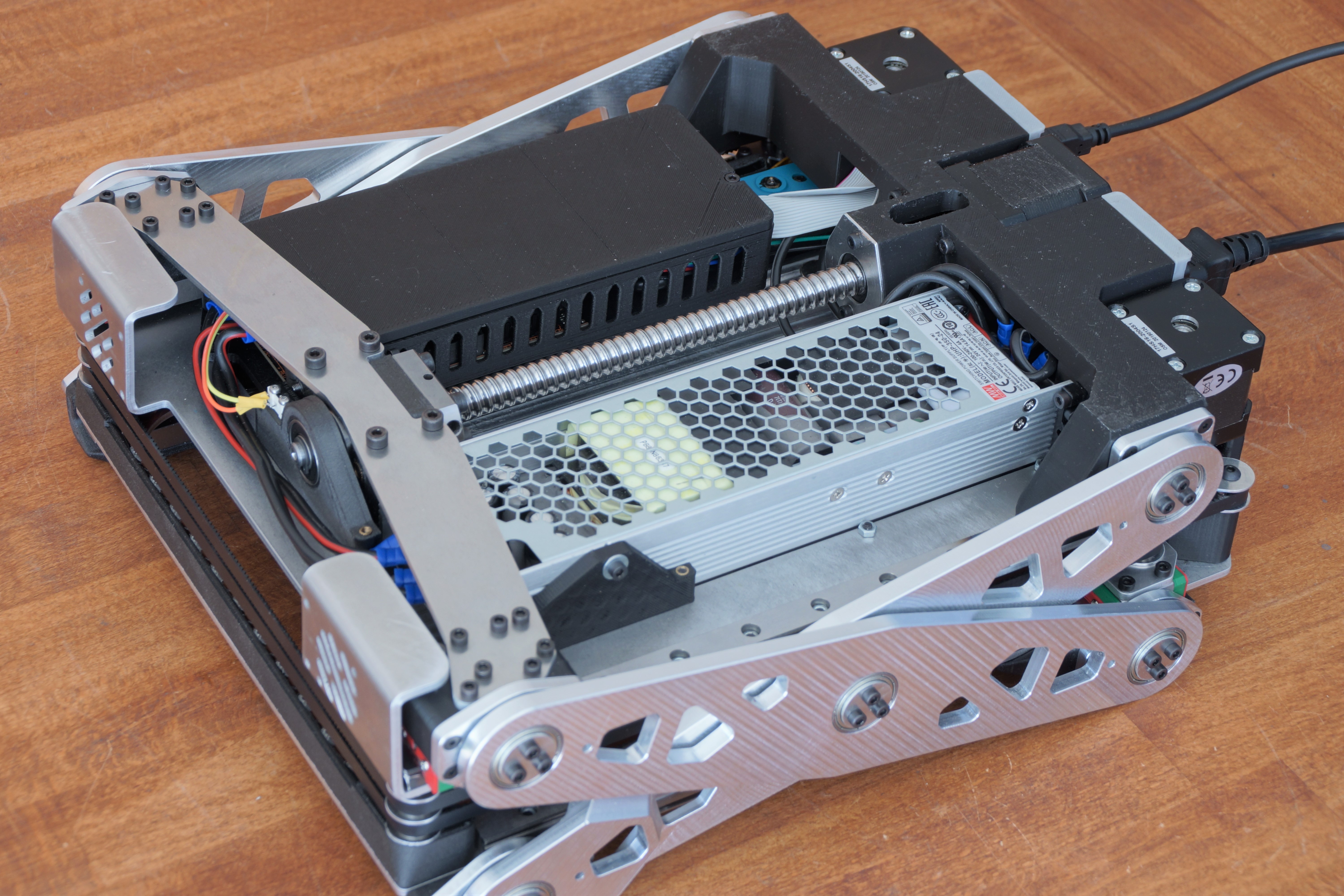
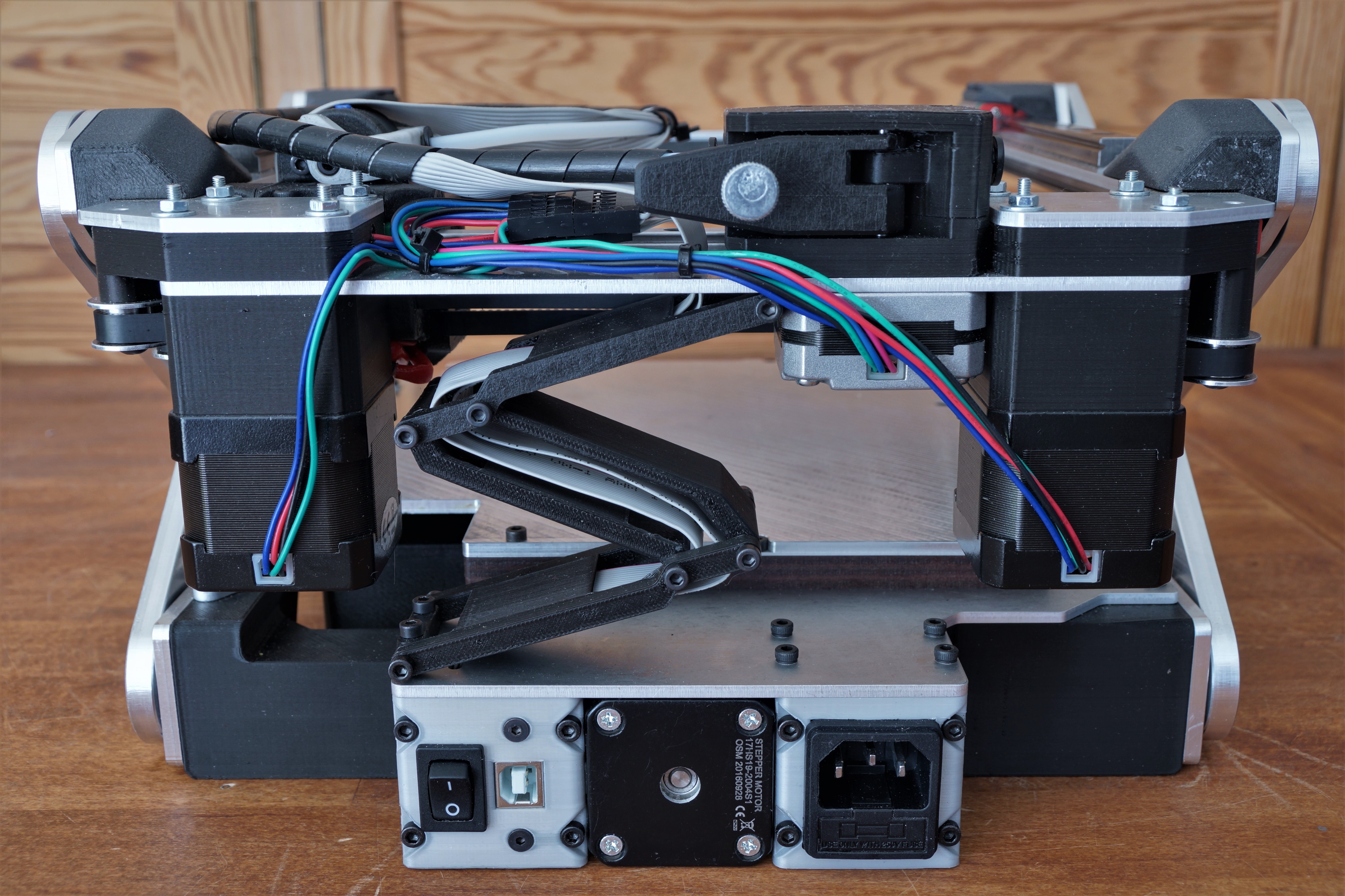
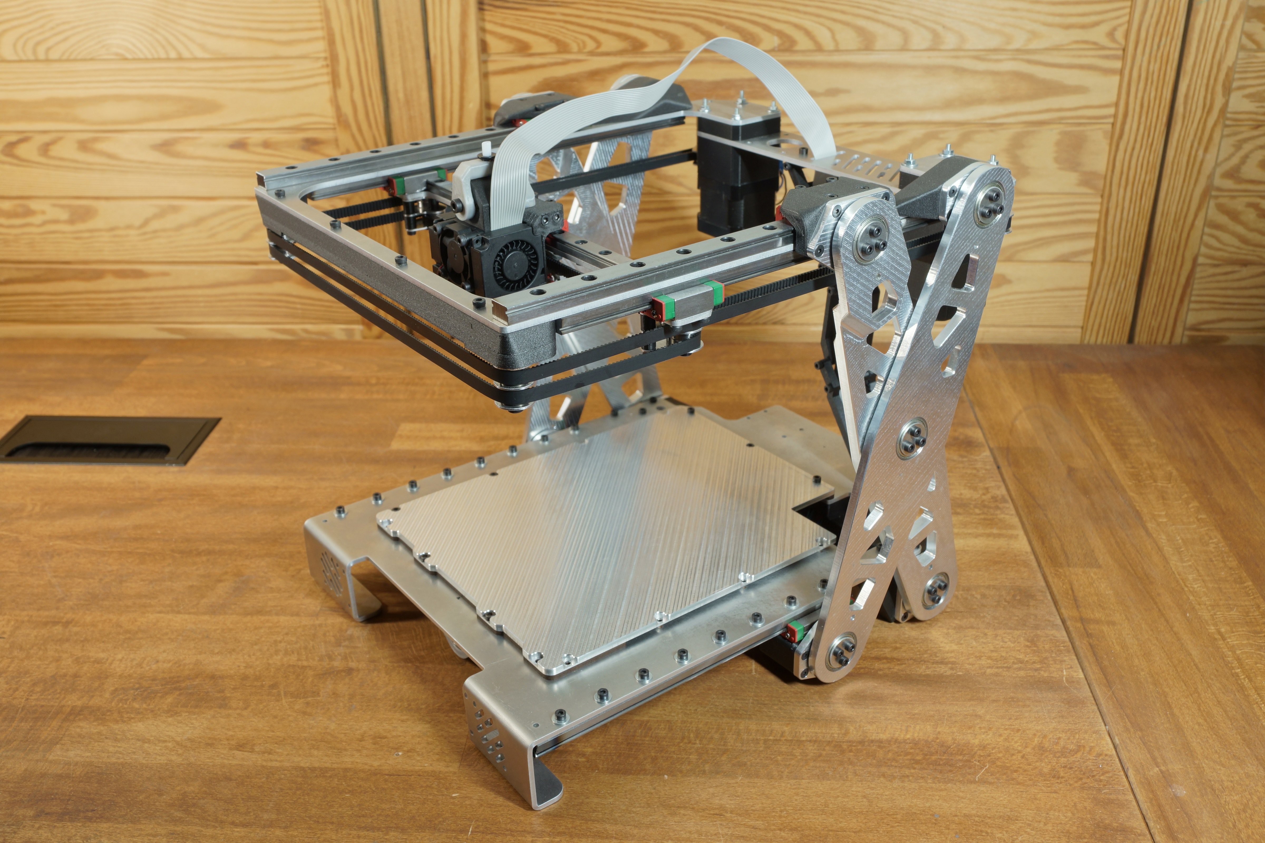
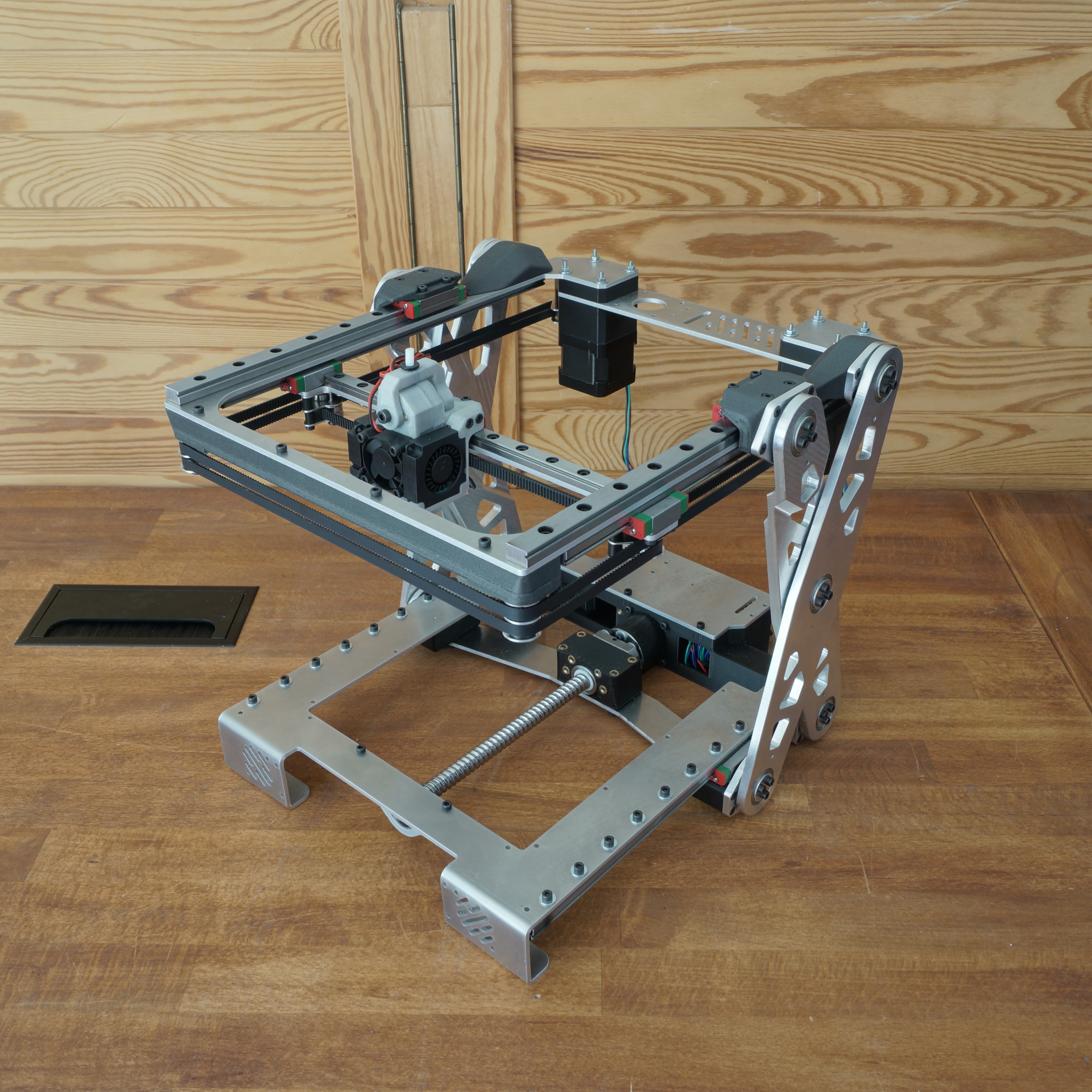
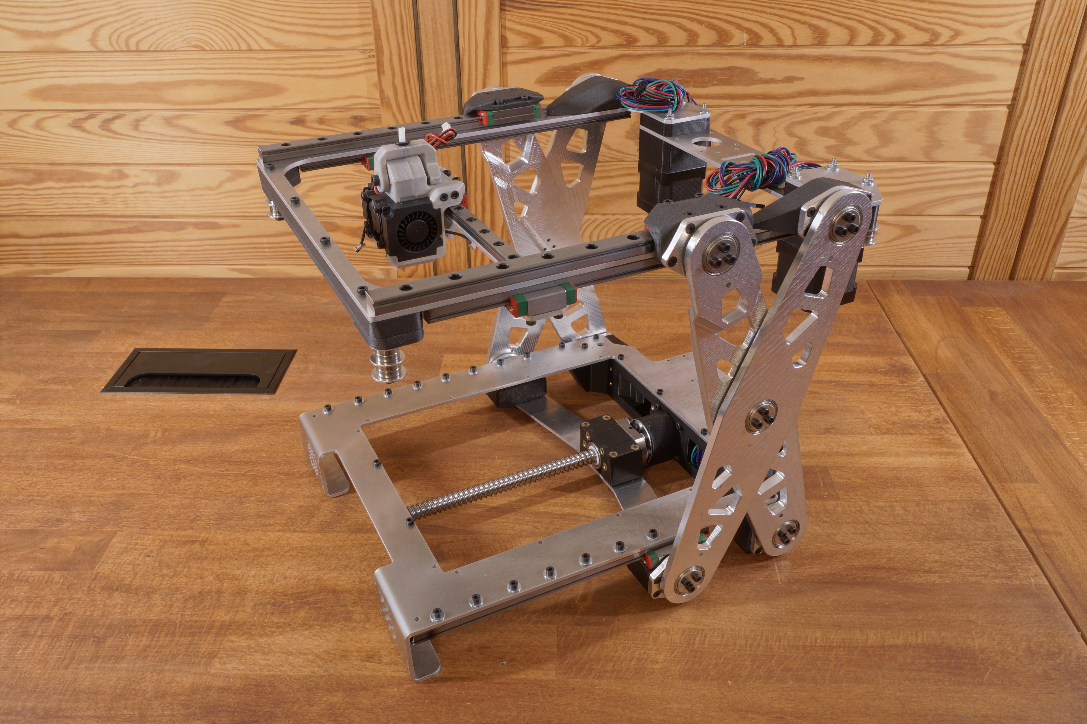
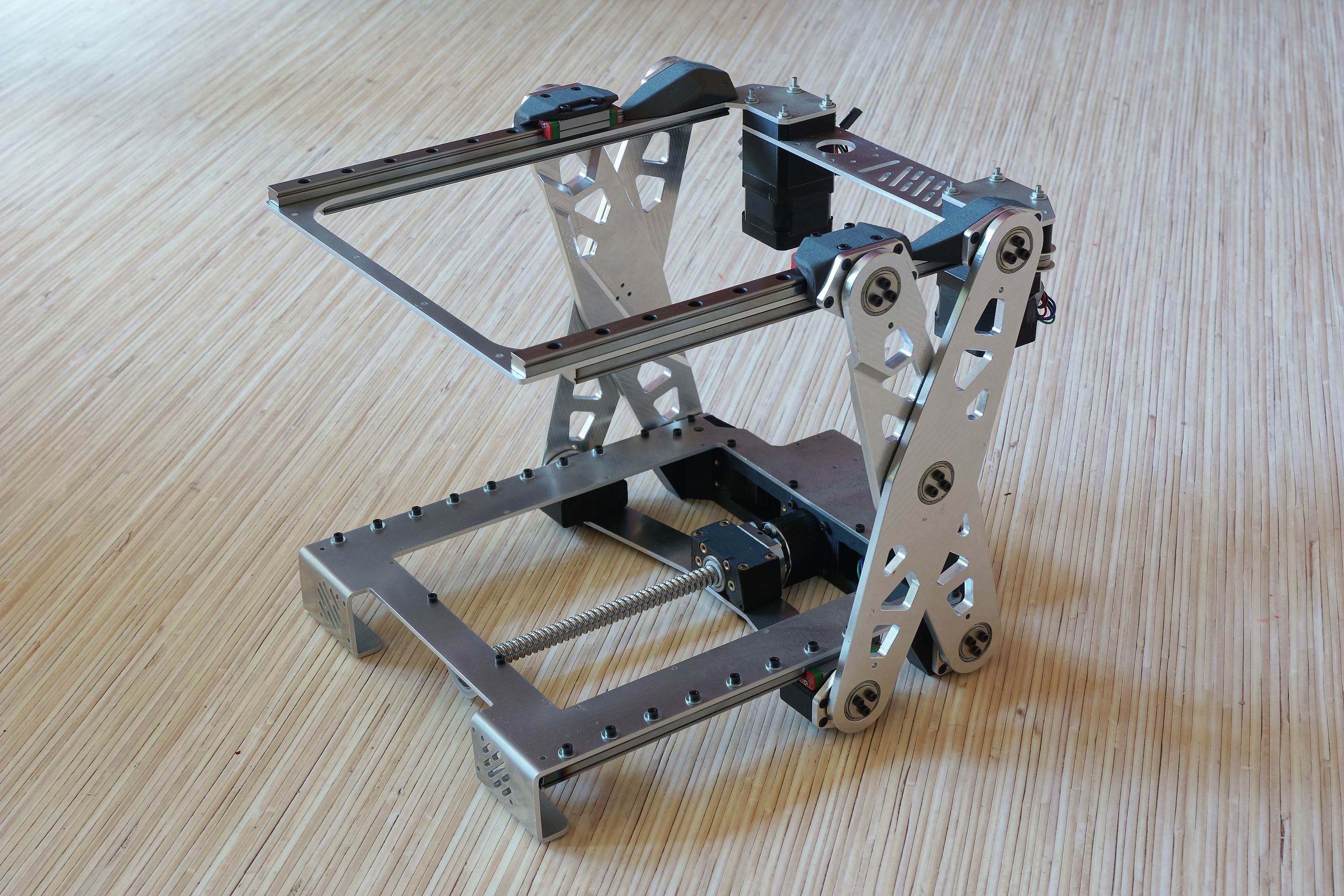
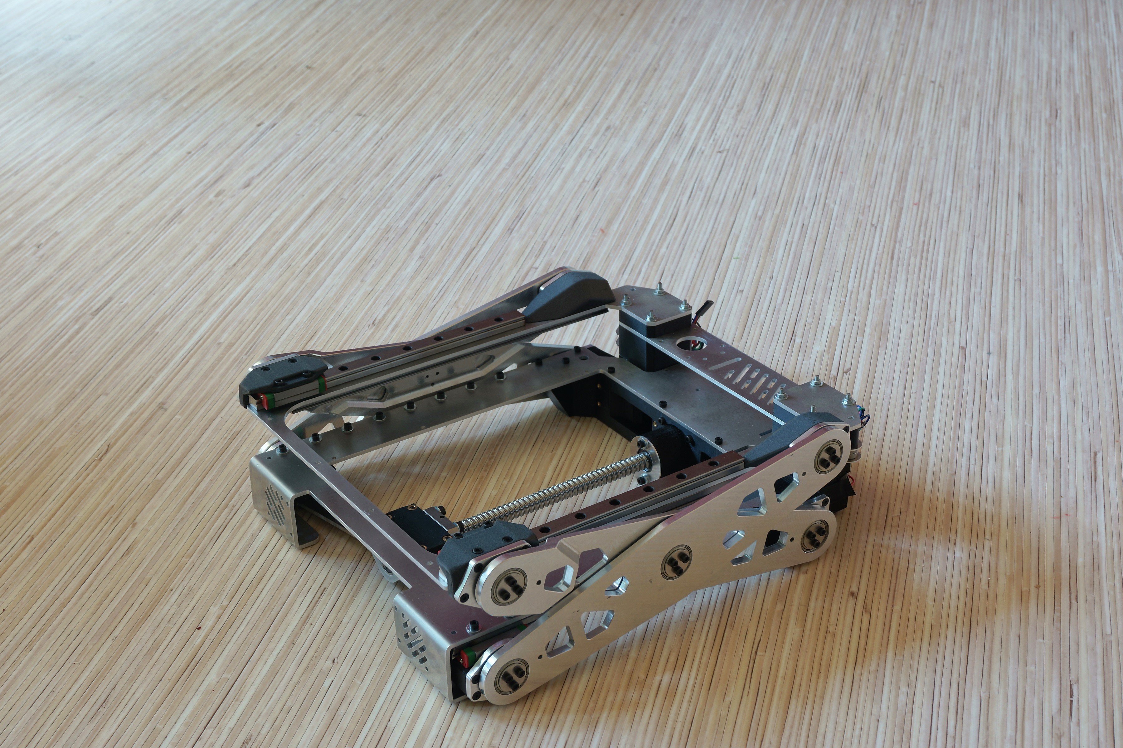
As you can see in the renderings, the printer will unfold during printing. The printer will be built out of CNC machined aluminum parts and 3d printed ones.
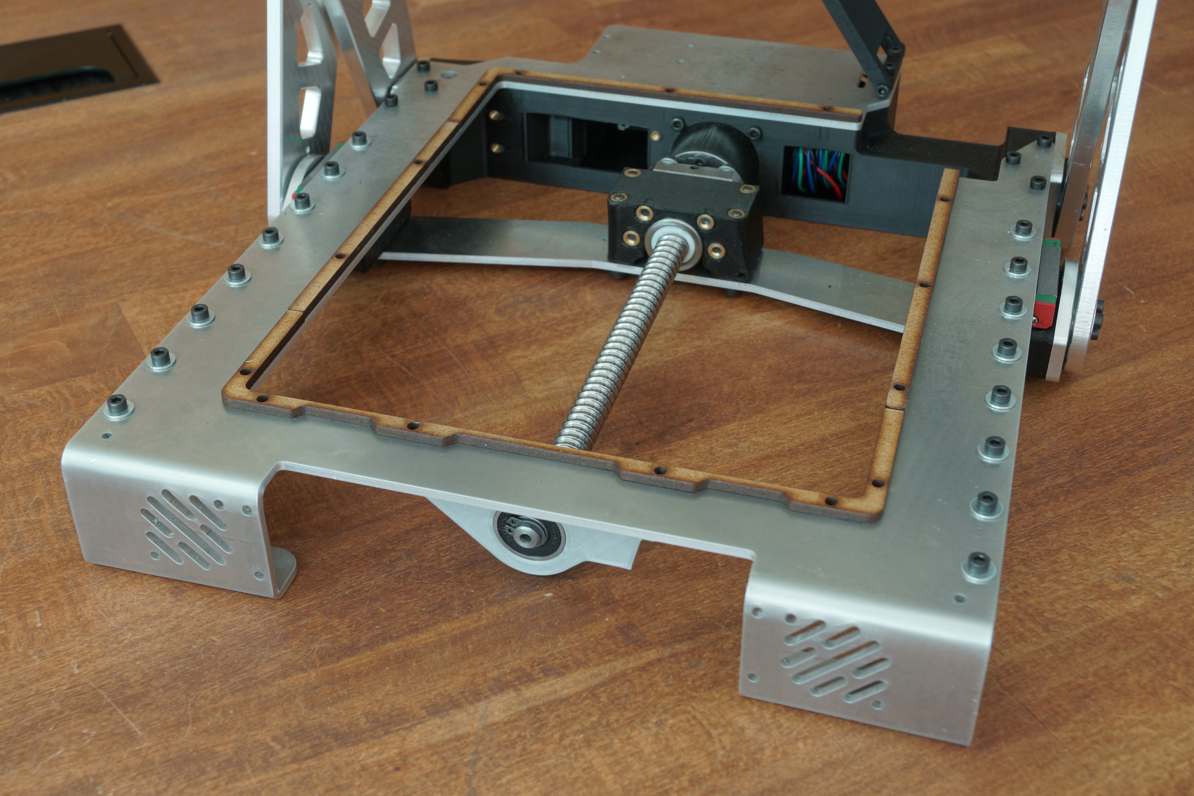
I chose aluminum in the first place because I wanted to build the printer as rigid as possible (proof of concept).
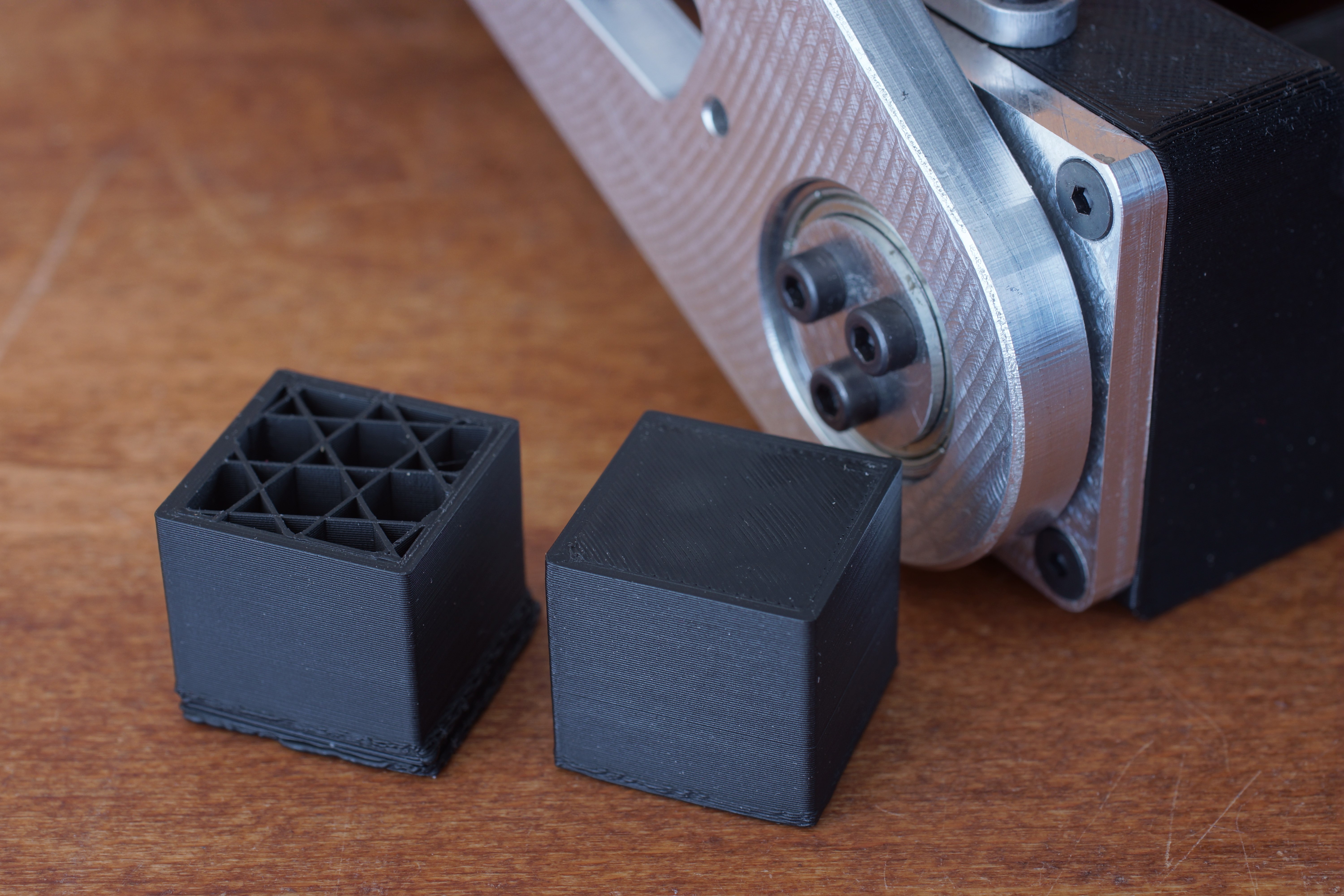
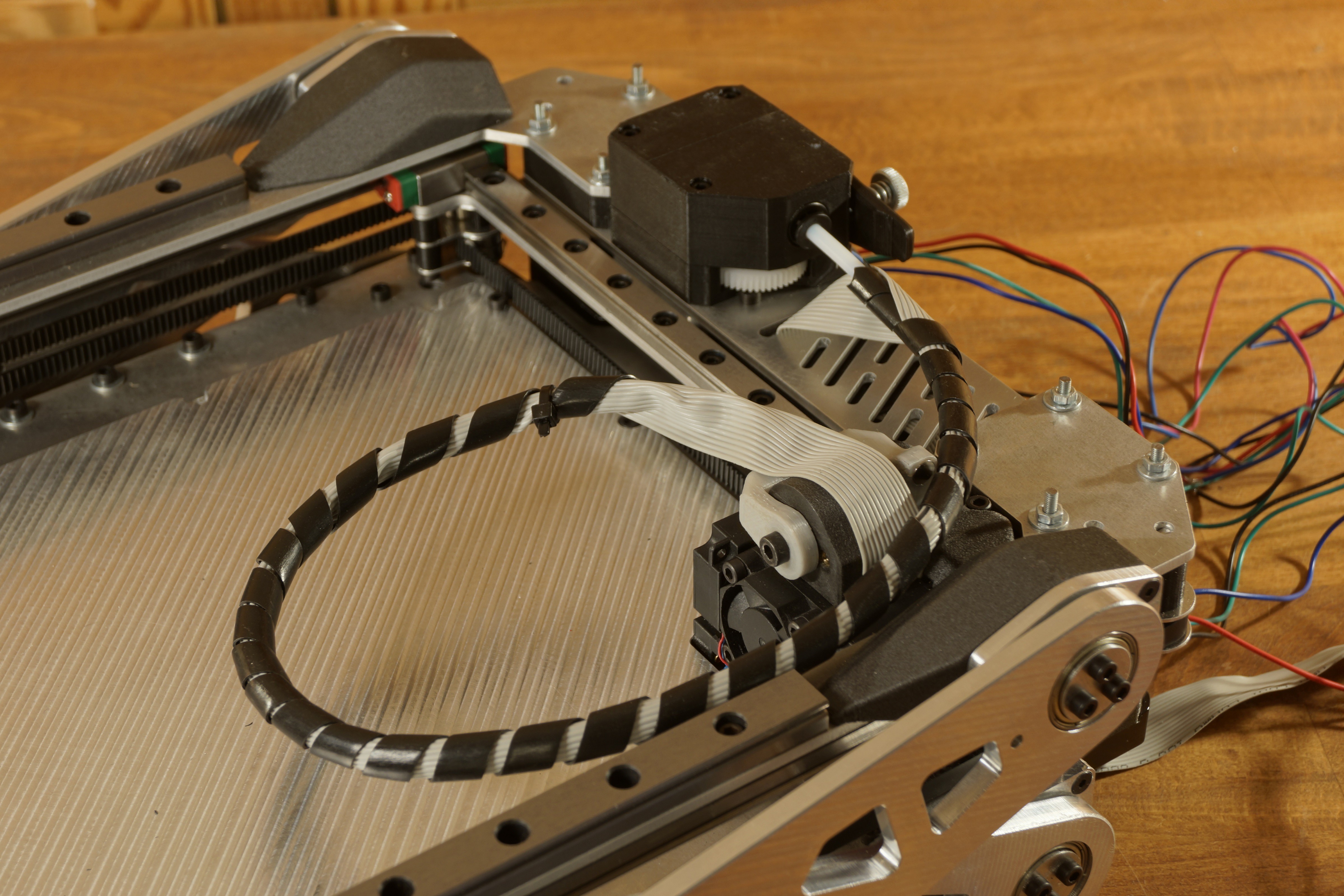
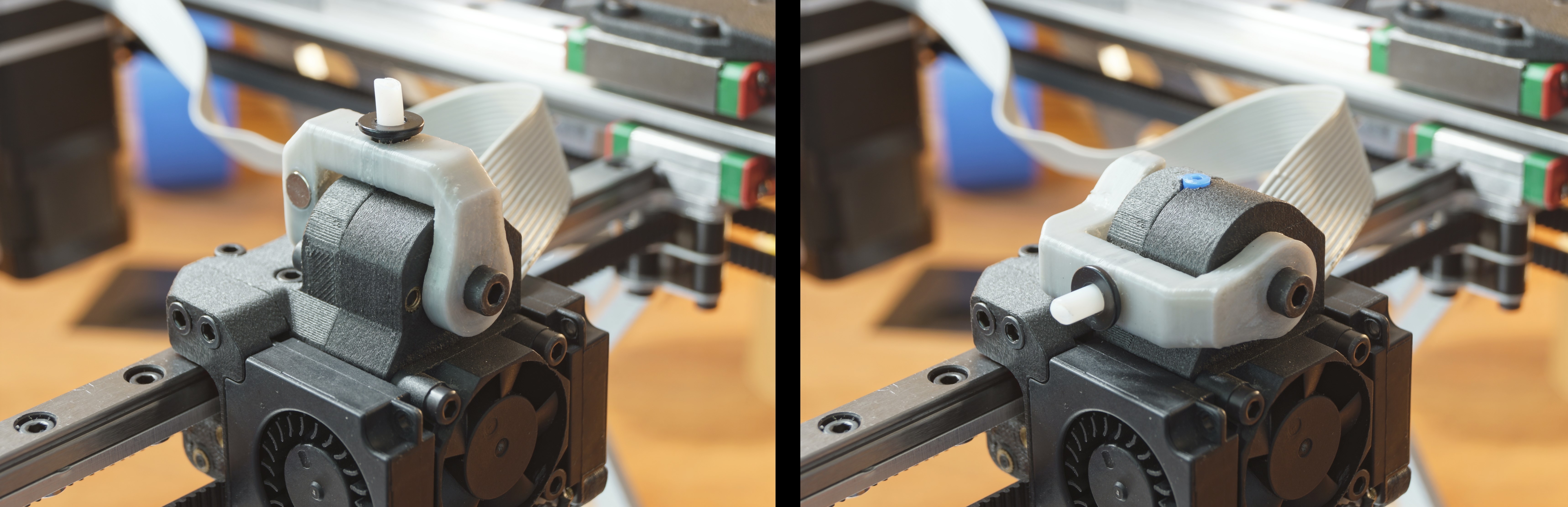
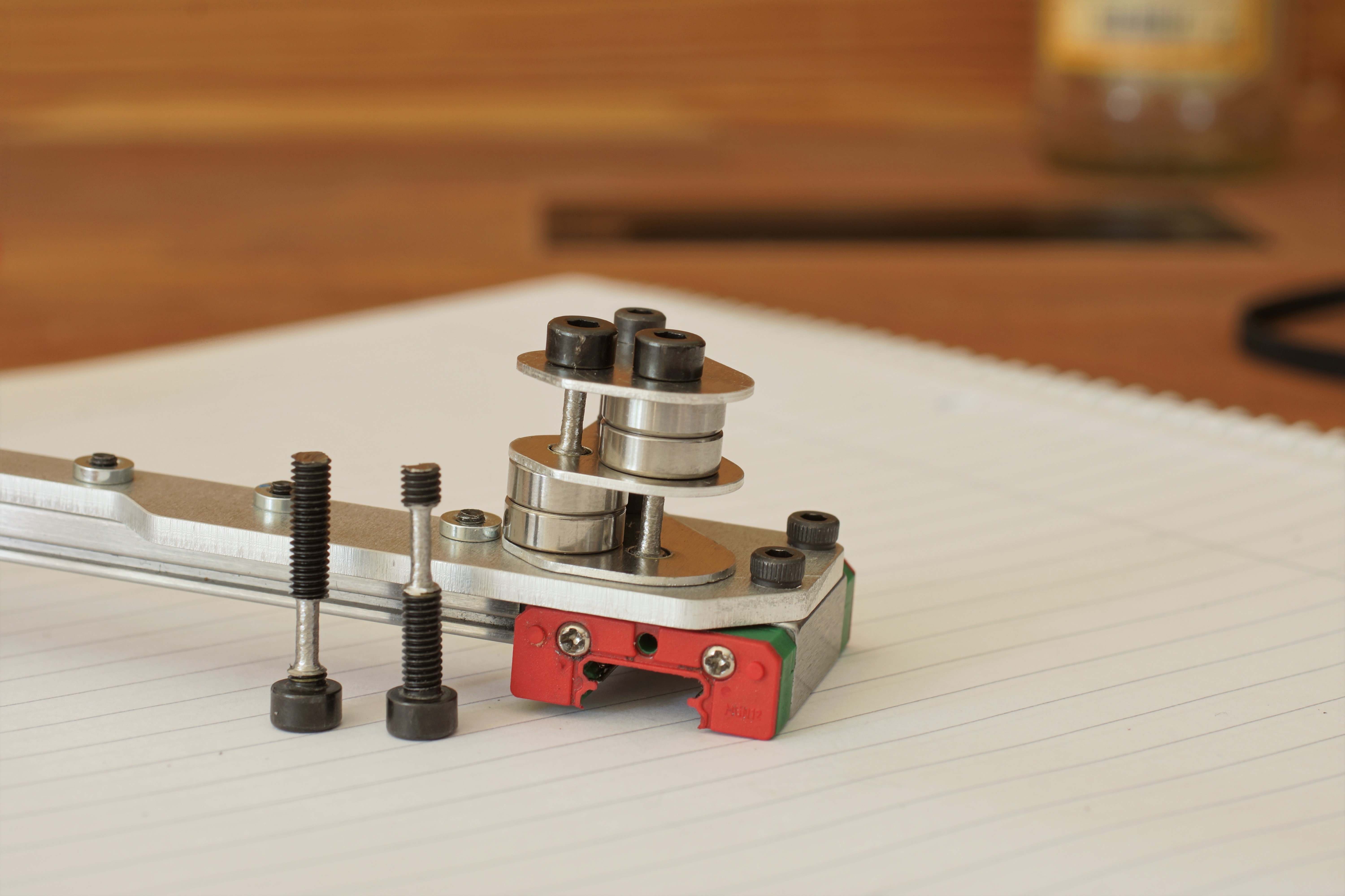
To obtain rigid joints, the printer uses a combination of axial and radial bearings. Three screws then preload each axial friction bearing.
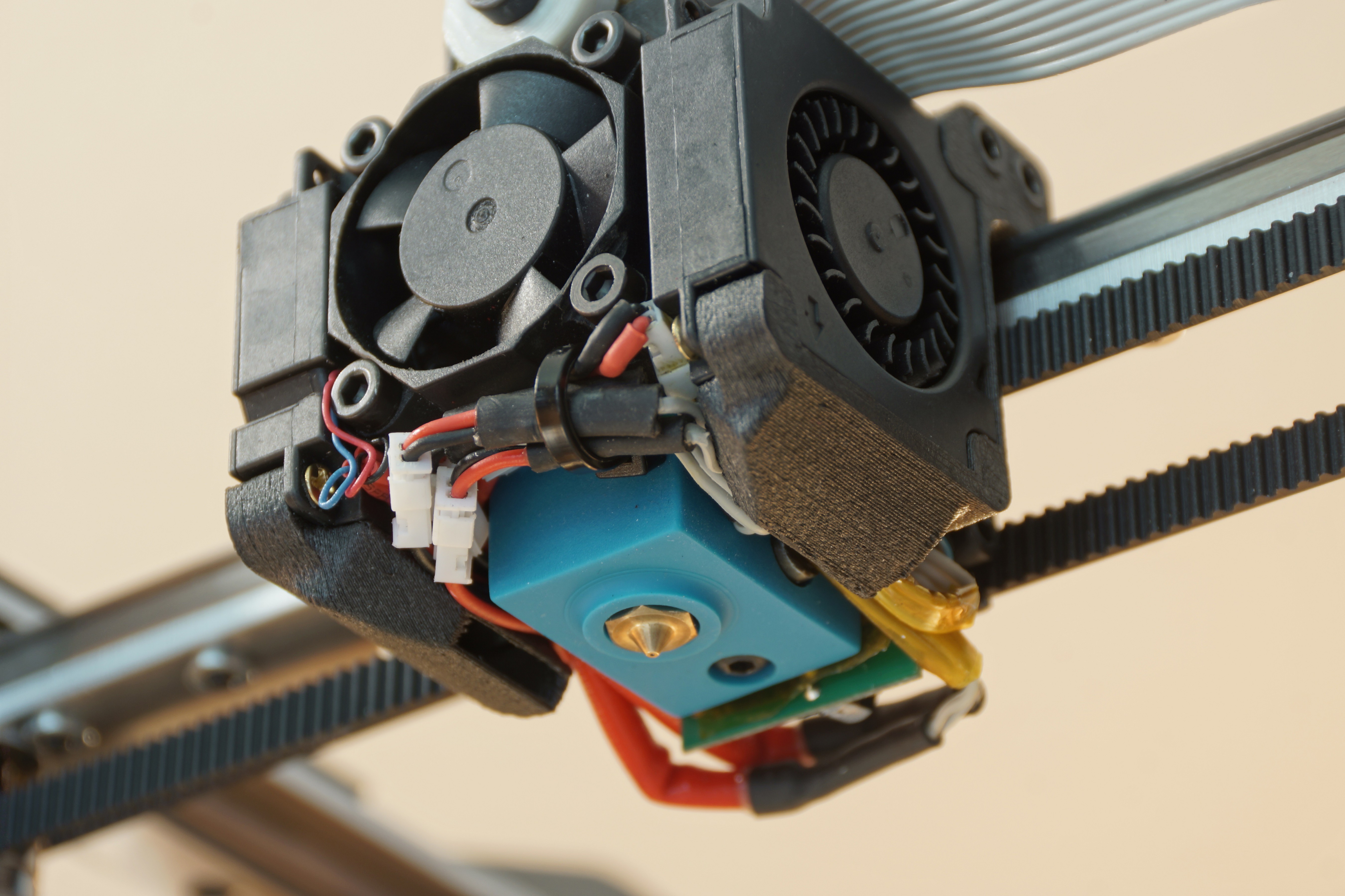
 For the first build, the friction bearings will glide directly on the aluminum. Later I want the aluminum parts to be hard anodized (for a better friction coefficient and to expand the lifetime of the friction bearings).
Due to the different Z-axis construction, the movement of the Z-motor is not linear to the Z-axis movement of the nozzle. When the printer is in the folded position, the Z-axis has a gear ratio of 1/4 to the printhead's Z-axis, which can cause several problems. The Z-motor has to be powerful enough to lift the upper structure, and the whole construction needs to be highly precise.
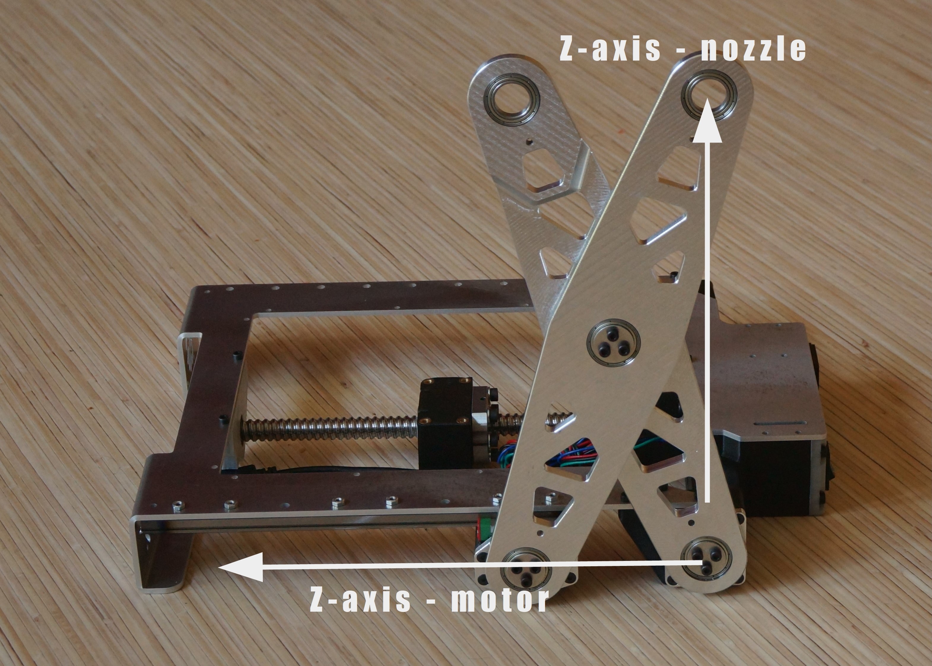
Technical challenge:
Because of the non-linear Z-axis I can't use the stock Marlin 2 firmware. A simple function can describe the dependency between the printhead's Z-axis and the real one (Pythagorean theorem). My problem is that I don't know how and where to add this dependency to the firmware.
Update: This problem has been solved. I added the formula for the non-linear Z-axis to the firmware.
Future plans:
After the first build, I want to try to replace as many Aluminium parts as possible with 3d printed ones to reduce the weight and to make the printer more RepRap friendly.
_
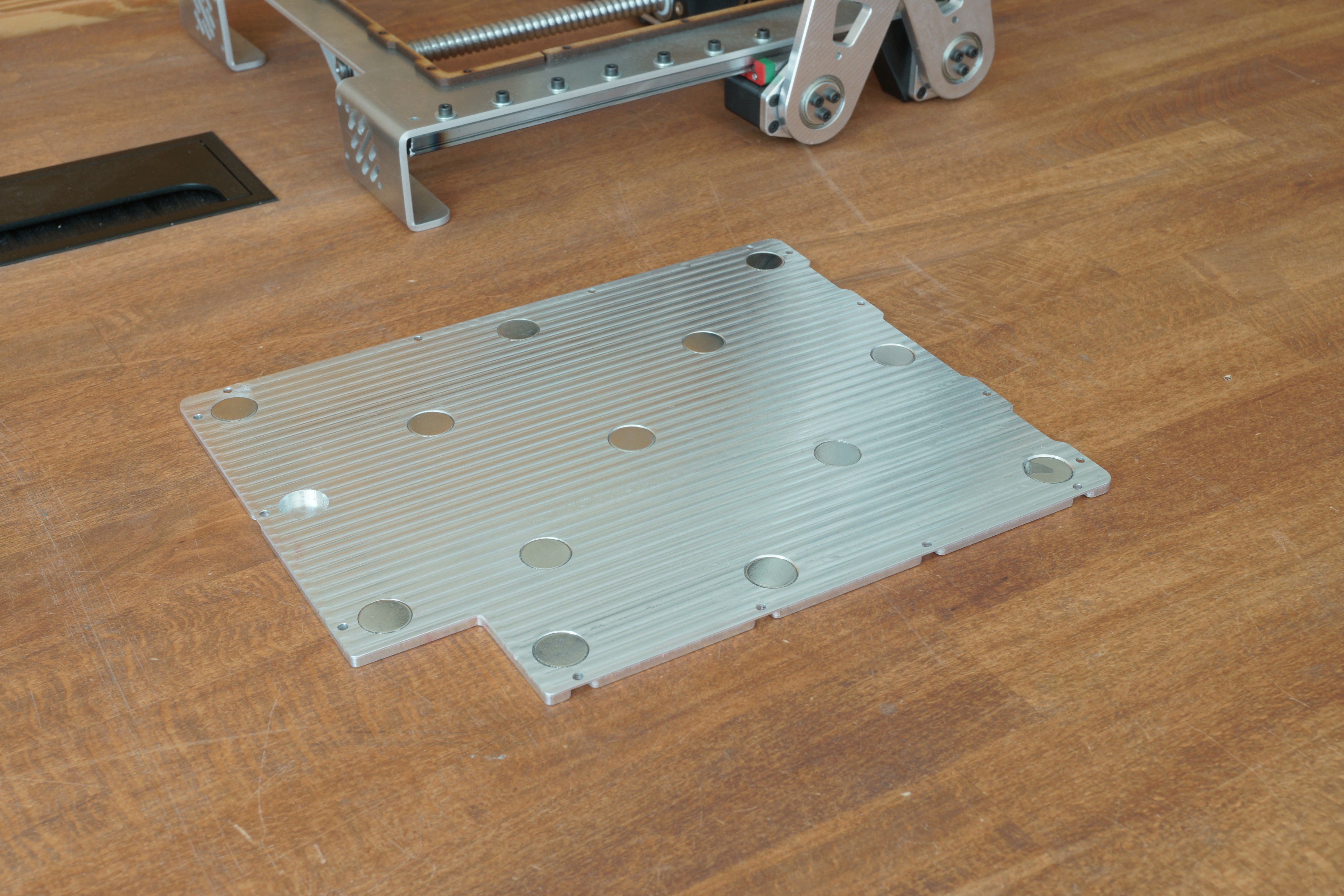
I designed the 3D printer in Fusion360 and I will publish everything under an open-source license after I finished the first build.
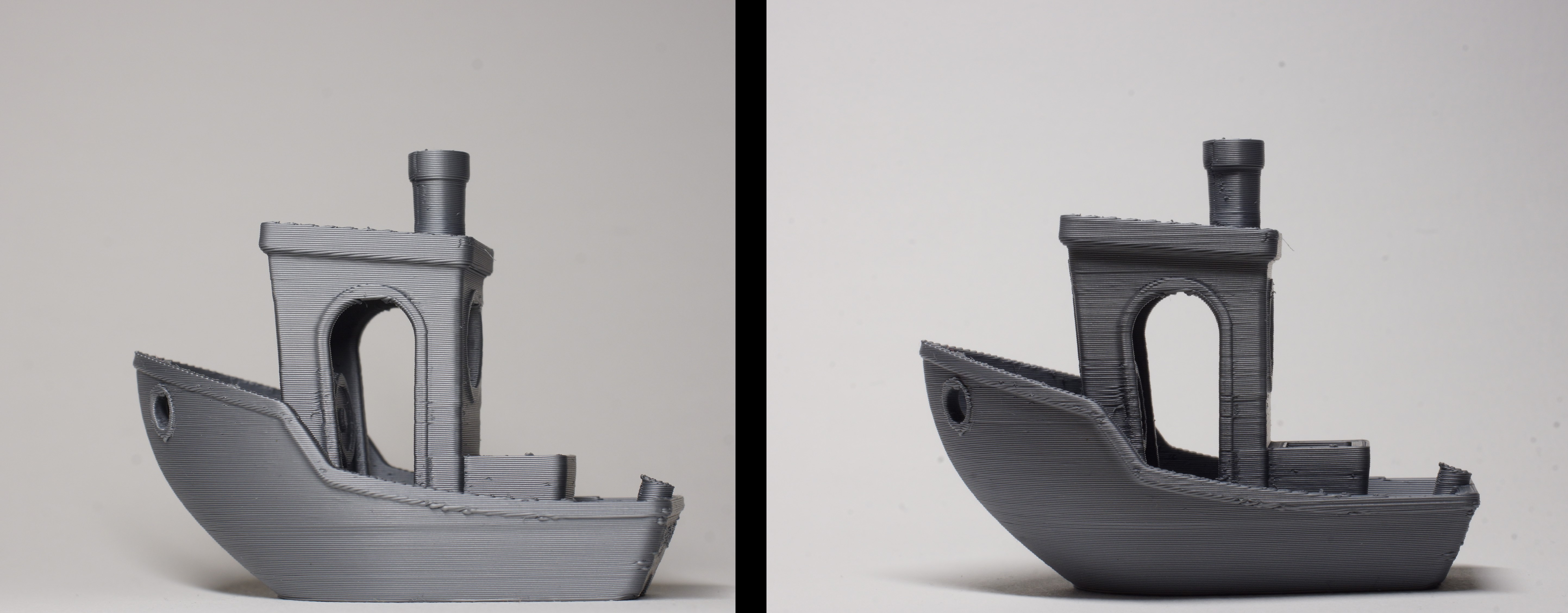
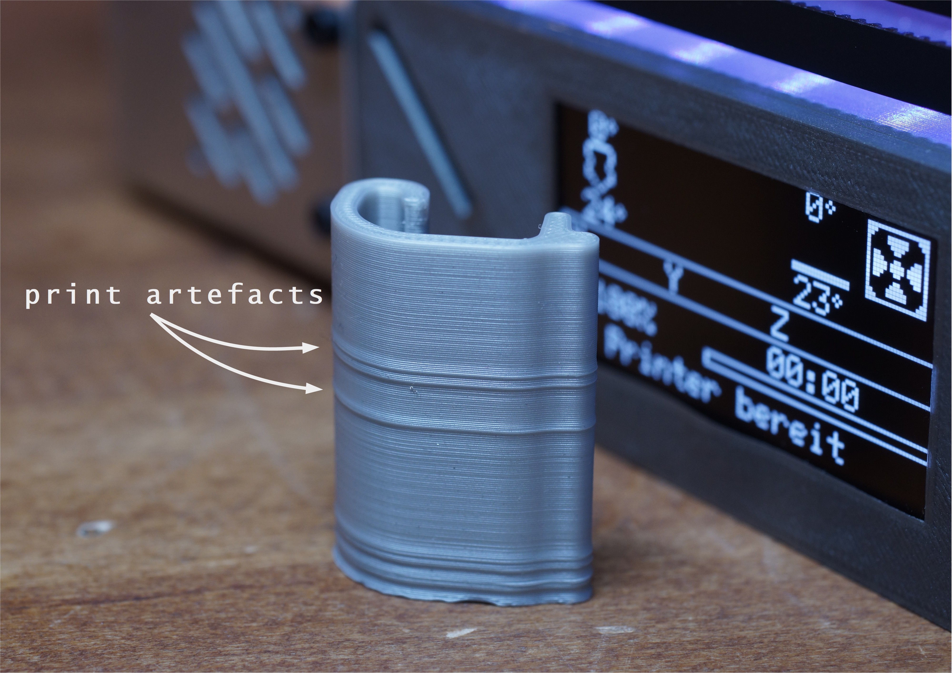
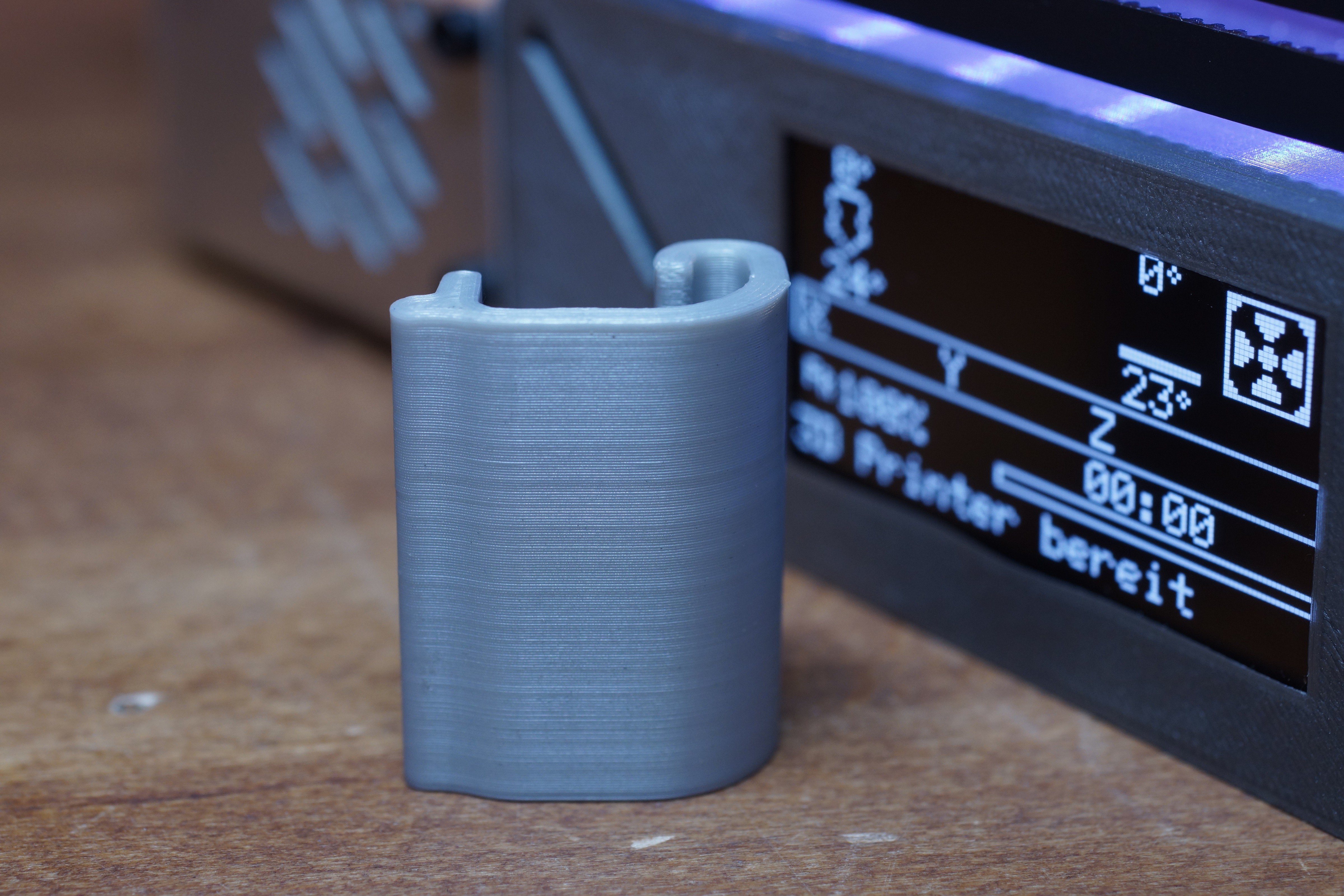
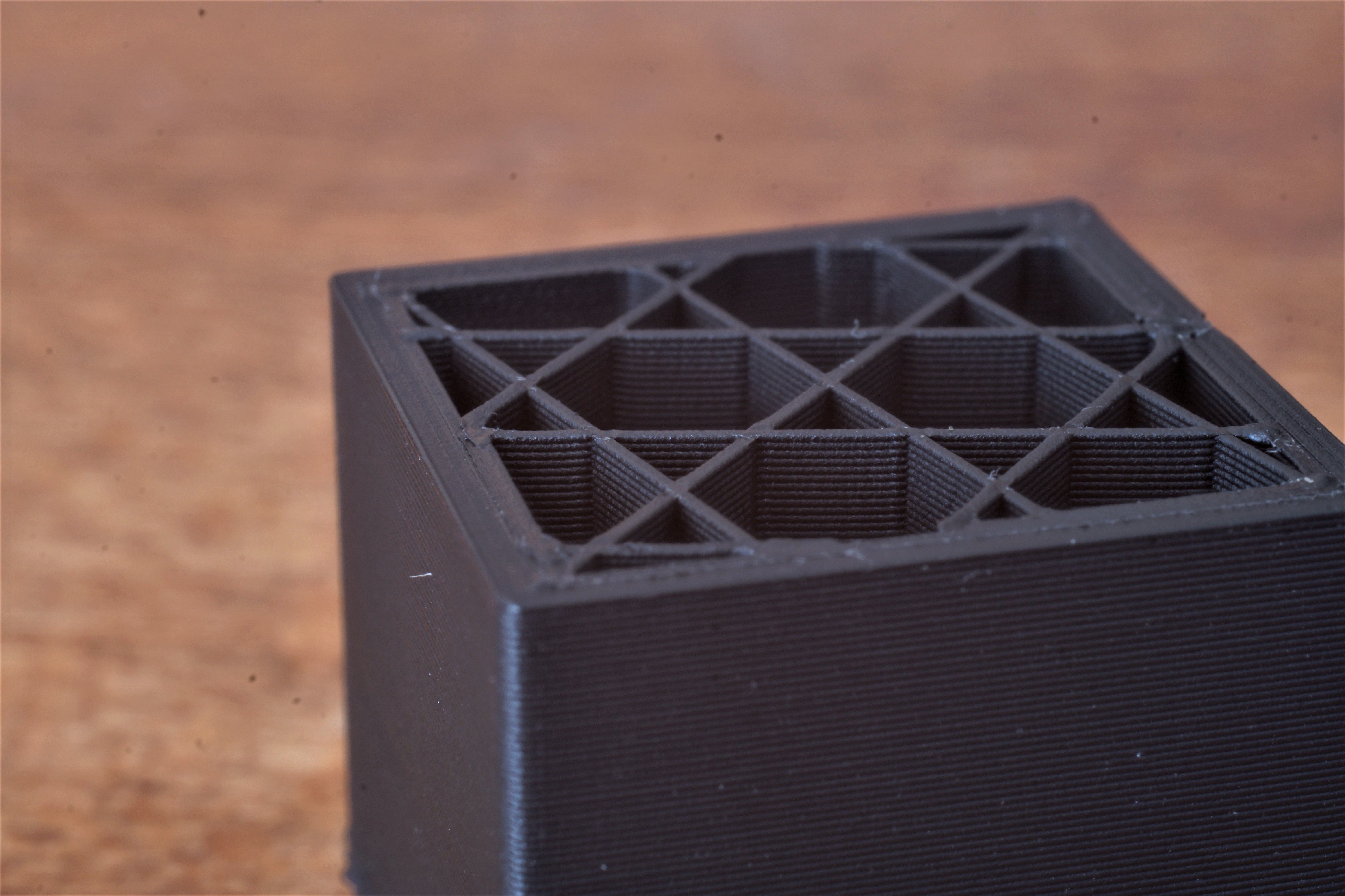
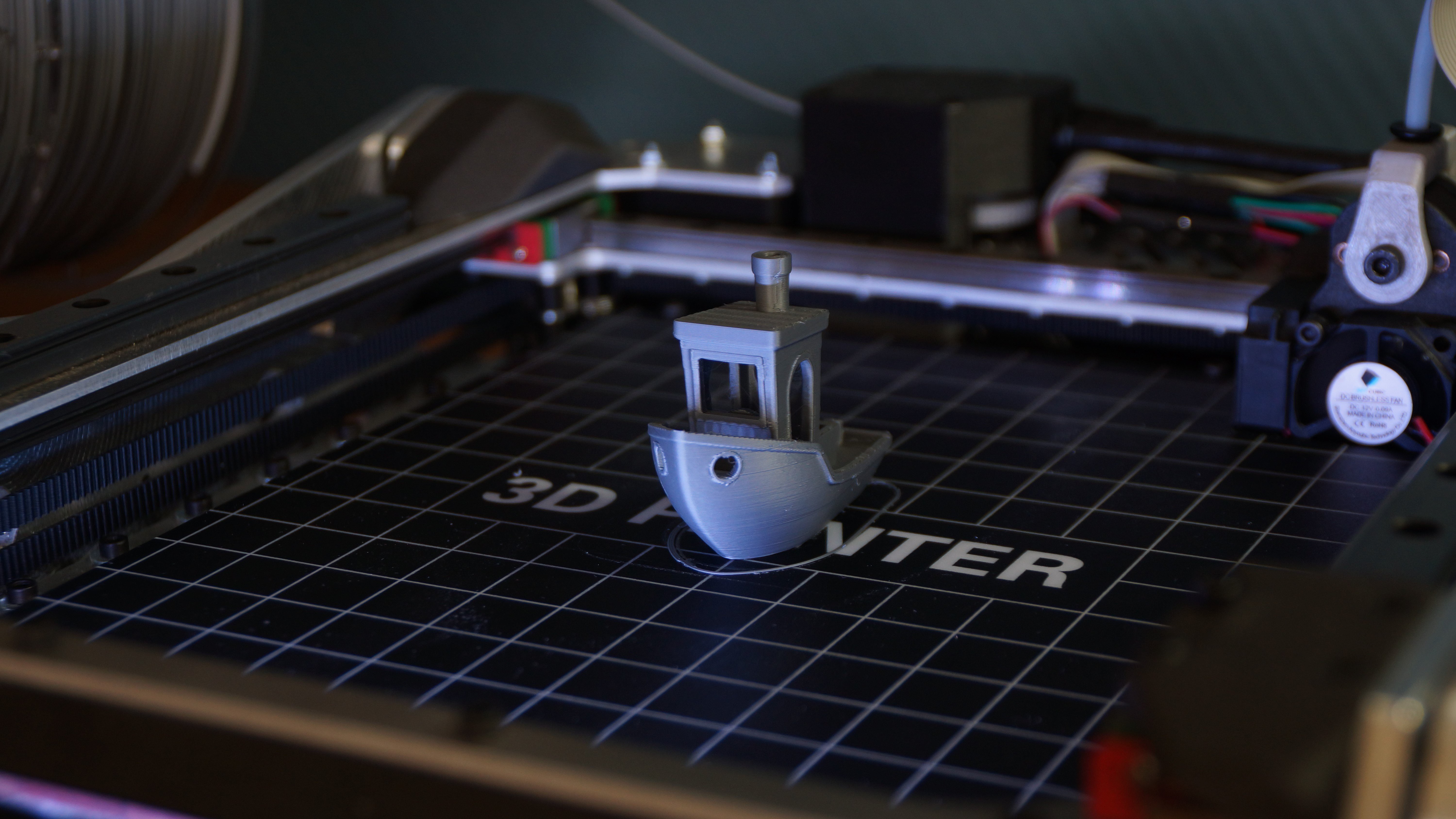 Layerheight: 0.2mm, print time: 78 minutes


 Saabman
 Benchoff
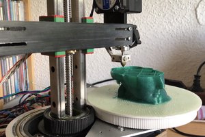
 heinz
heinz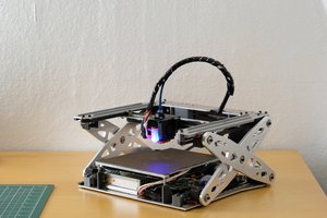
marlin2.0的Z轴怎么修改,可有人知道??不想用1.0。