Close
0%
0%

X printer - portable

Portable CoreXY 3D printer
(foldable)

Public Chat
Similar projects worth following
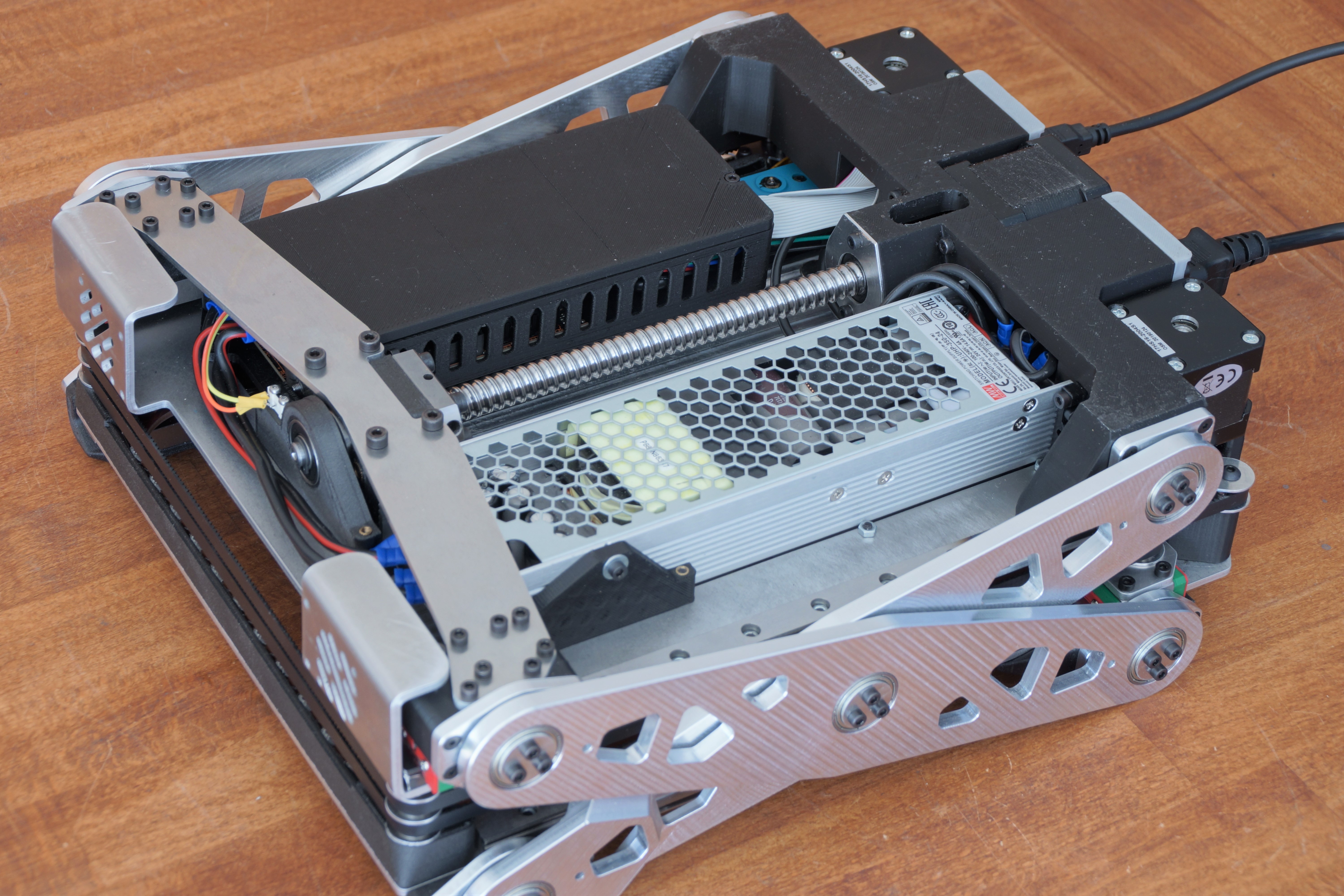
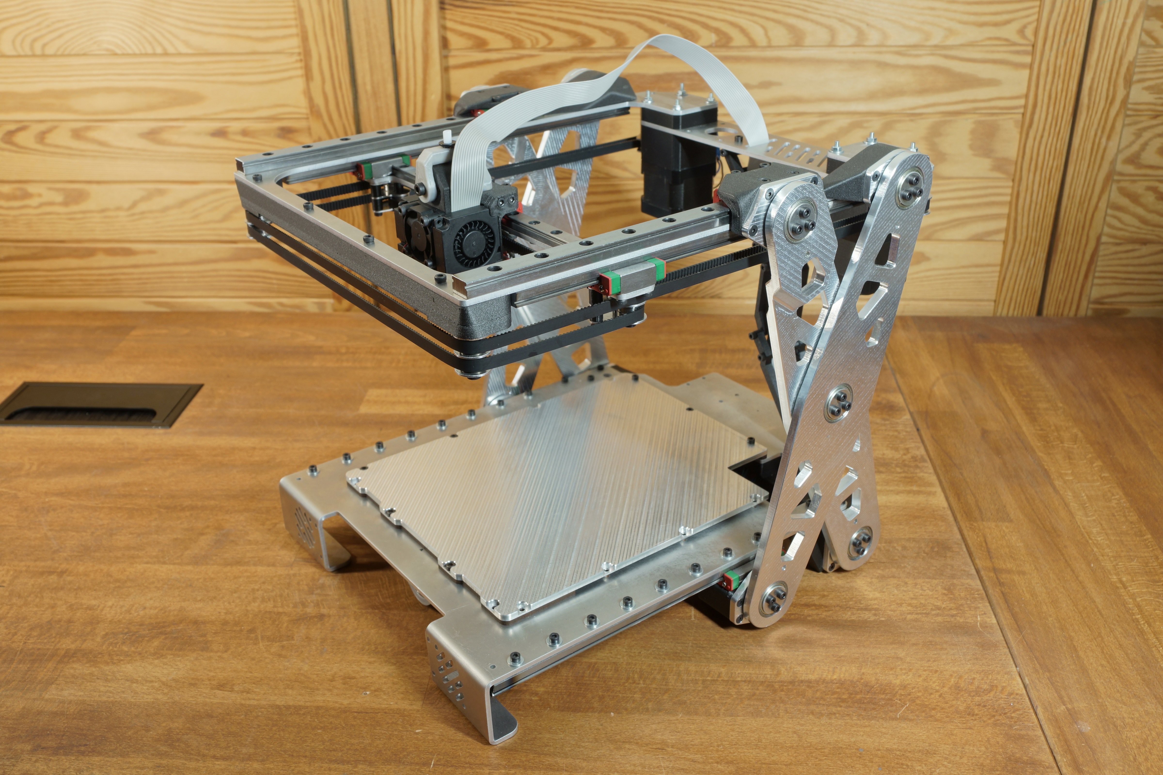
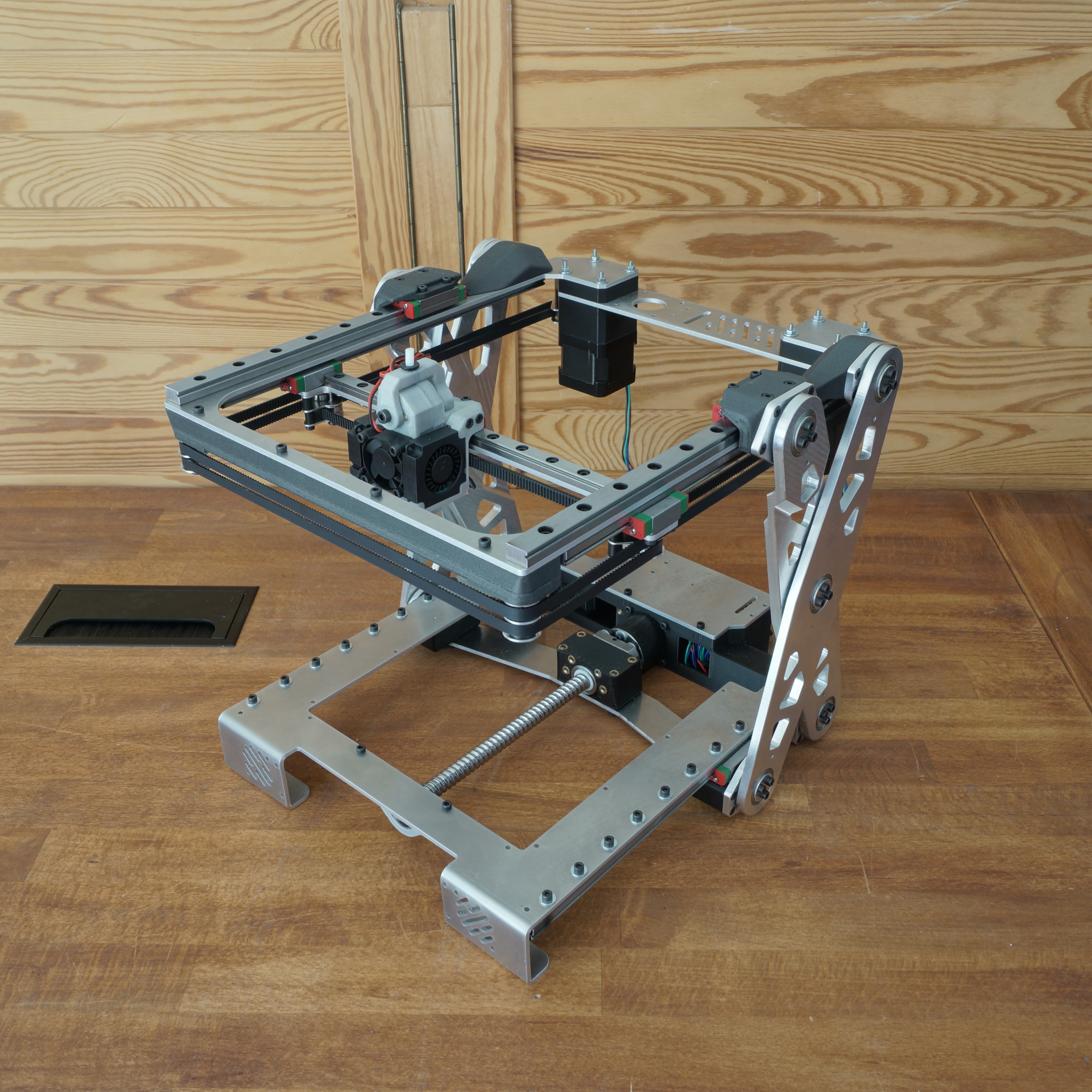
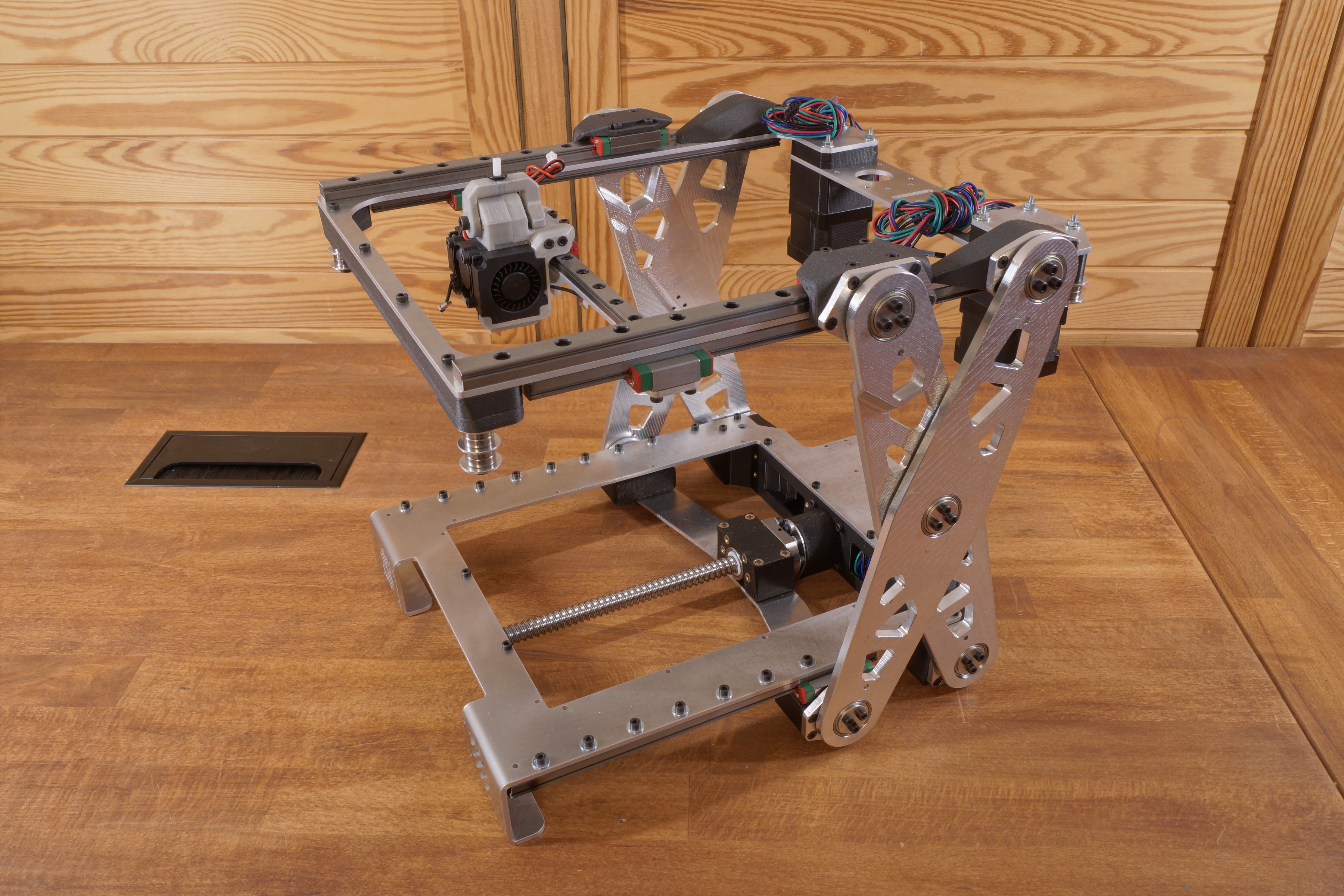
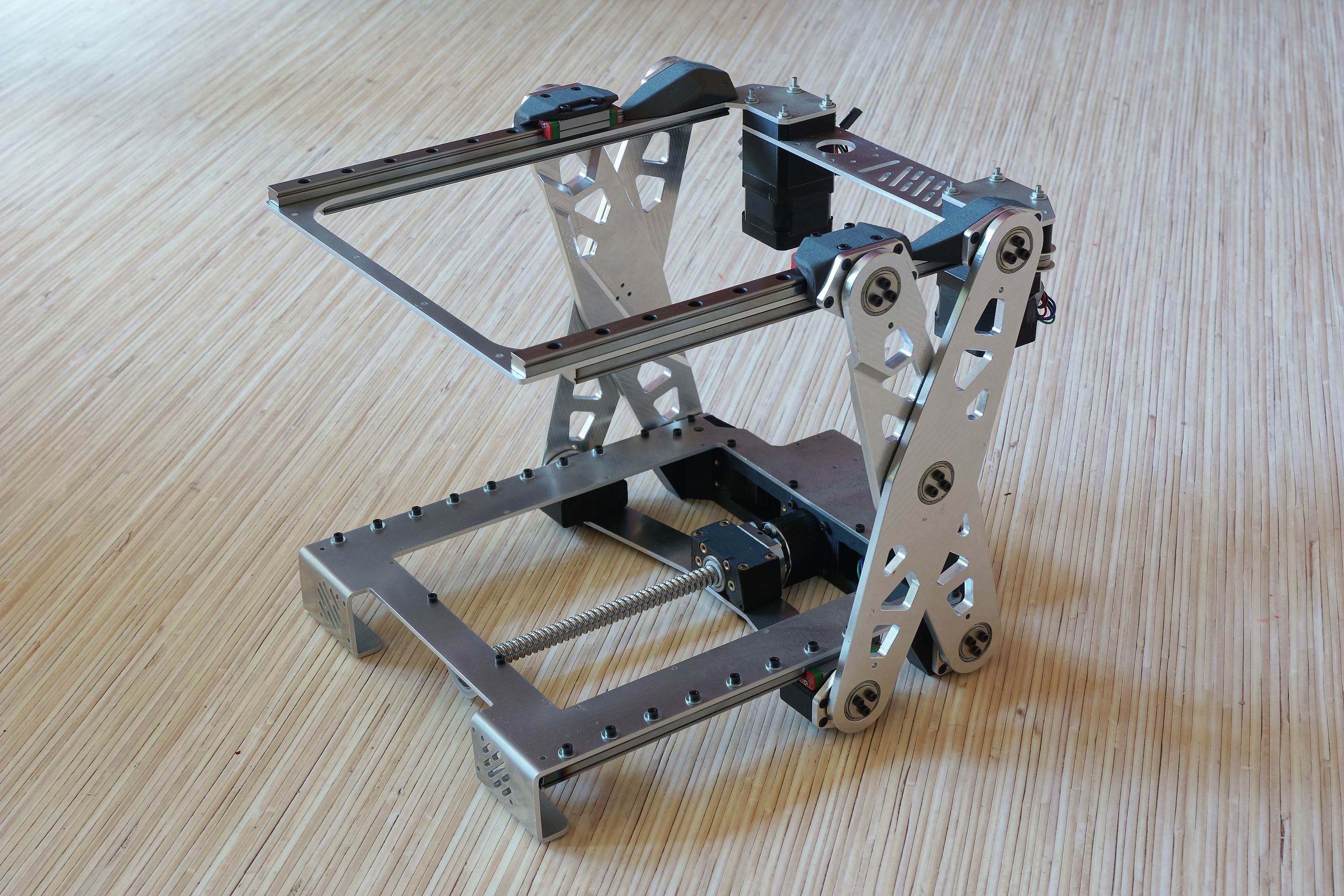
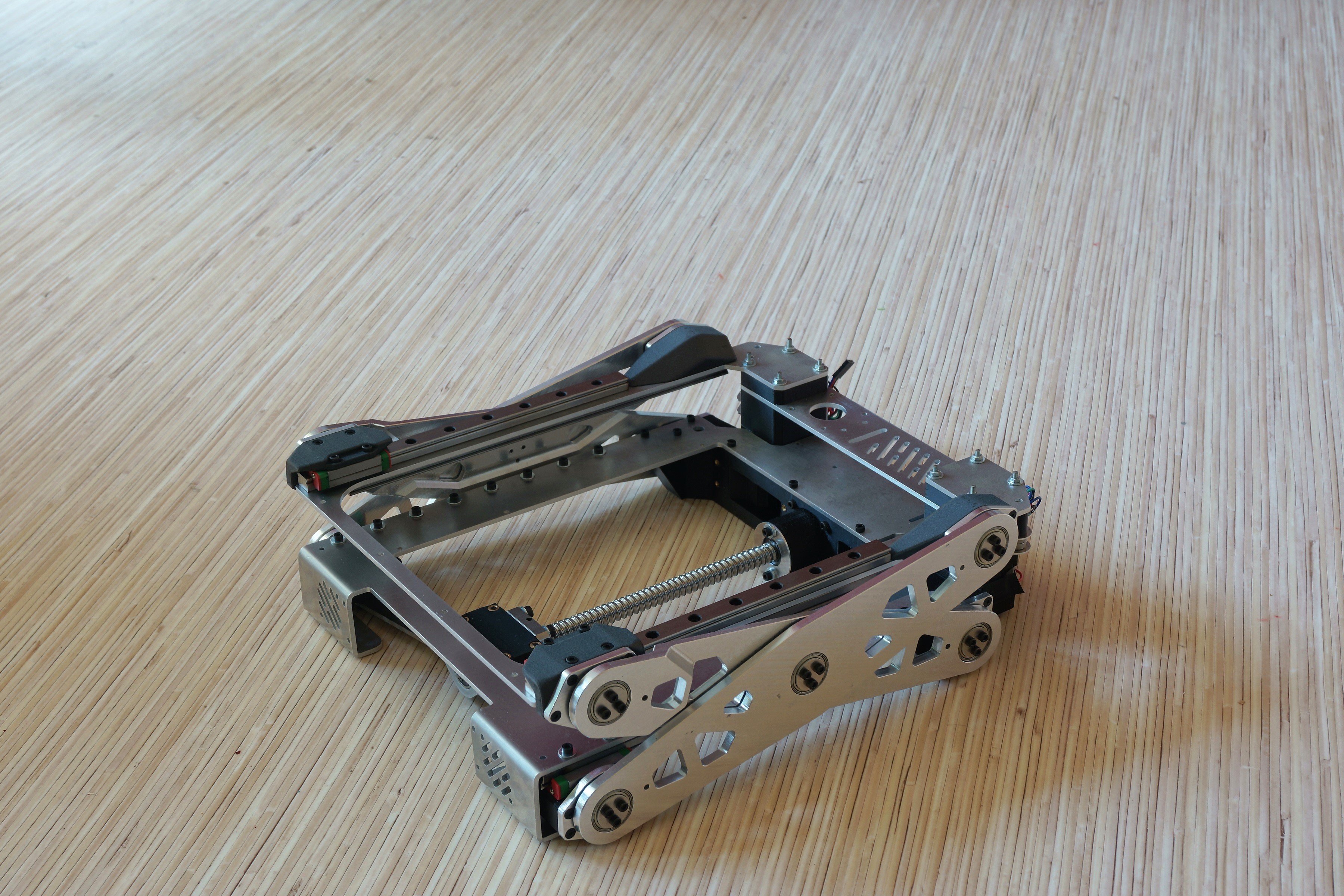
The 3D printer has a compact size so that it can fit in a large backpack. It was essential for me that the printer has a reasonable print volume despite the requirement to be portable.
The outer dimensions are 300x330x105mm (folded), and the build volume will be 160x220x150mm (XYZ).

As you can see in the renderings, the printer will unfold during printing. The printer will be built out of CNC machined aluminum parts and 3d printed ones.
I chose aluminum in the first place because I wanted to build the printer as rigid as possible (proof of concept).

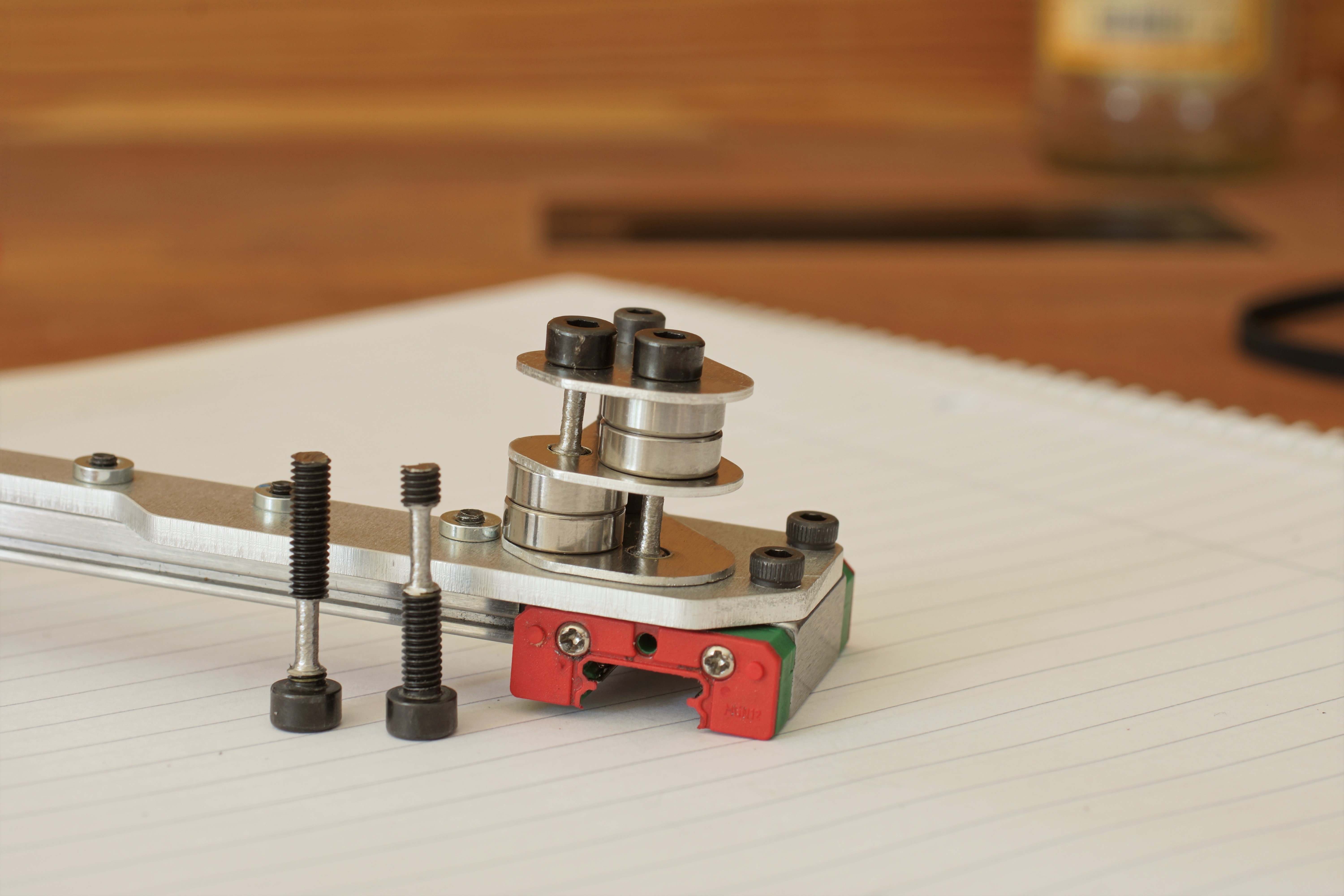
To obtain rigid joints, the printer uses a combination of axial and radial bearings. Three screws then preload each axial friction bearing.

jointFor the first build, the friction bearings will glide directly on the aluminum. Later I want the aluminum parts to be hard anodized (for a better friction coefficient and to expand the lifetime of the friction bearings).

Due to the different Z-axis construction, the movement of the Z-motor is not linear to the Z-axis movement of the nozzle. When the printer is in the folded position, the Z-axis has a gear ratio of 1/4 to the printhead's Z-axis, which can cause several problems. The Z-motor has to be powerful enough to lift the upper structure, and the whole construction needs to be highly precise.
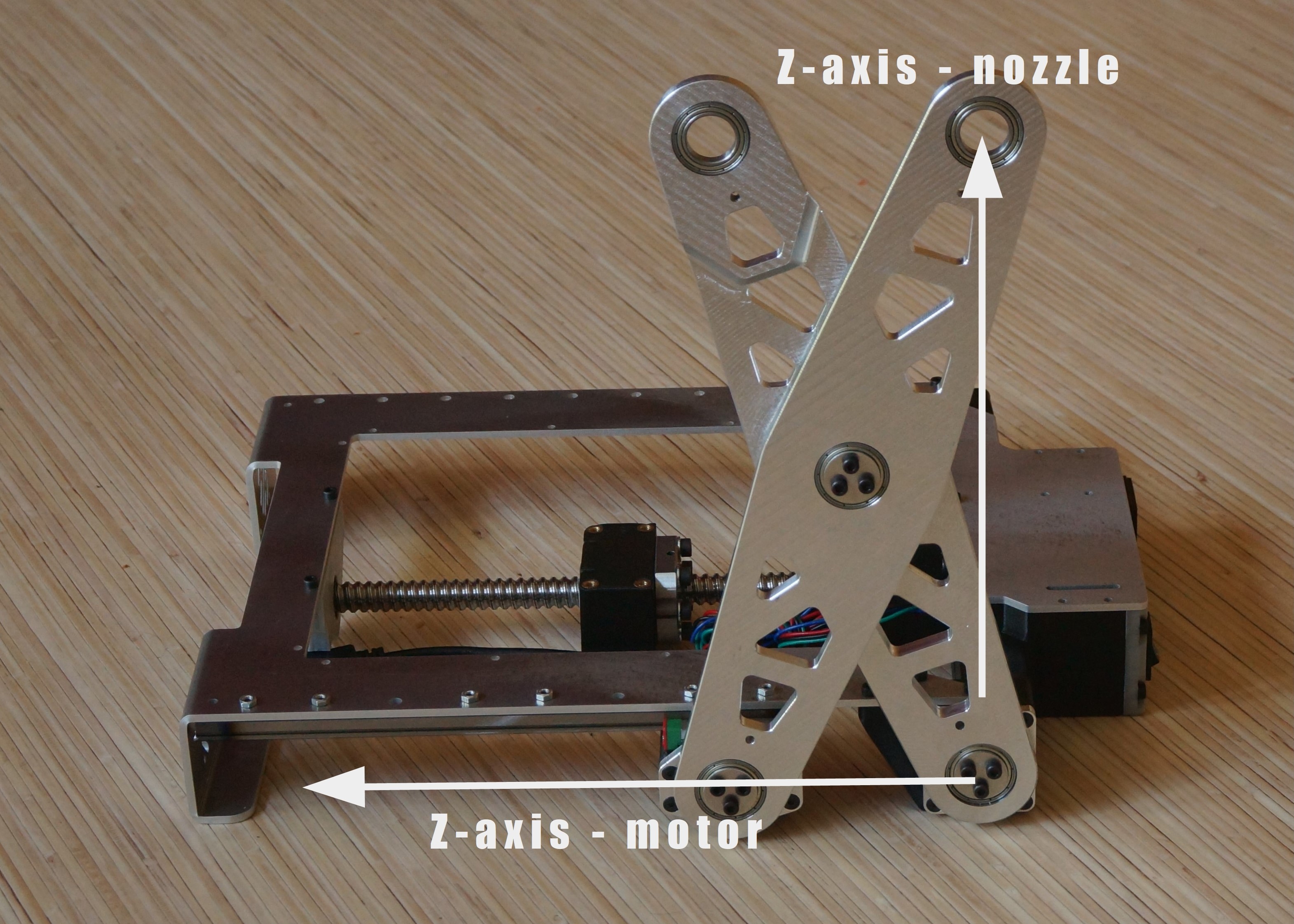

Technical challenge:

Because of the non-linear Z-axis I can't use the stock Marlin 2 firmware. A simple function can describe the dependency between the printhead's Z-axis and the real one (Pythagorean theorem). My problem is that I don't know how and where to add this dependency to the firmware.

Update: This problem has been solved. I added the formula for the non-linear Z-axis to the firmware.


Future plans:

After the first build, I want to try to replace as many Aluminium parts as possible with 3d printed ones to reduce the weight and to make the printer more RepRap friendly.


_

I designed the 3D printer in Fusion360 and I will publish everything under an open-source license after I finished the first build.

  • 1 × Einsy Rambo Board small, low profile board
  • 1 × MGN9 linear guide X-axis
  • 1 × UHP-350-24 Mean Well power supply 350W 24V power supply which will be integrated into the printer
  • 1 × V6 hotend clone
  • 1 × 2.42 Inch 128x64p OLED display

View all 10 components

  • V2 Build - new project page

    Malte Schrader06/14/2021 at 21:26 0 comments

    I'm starting to build a second version of the printer. The V1 was my first attempt to build this style of 3D-printer. V1 was already quiet good but has still some problems which I want to solve in V2.

    The new project page can be found here.


  • 3DBenchys + Z-homing problem

    Malte Schrader03/25/2020 at 23:55 2 comments

    I couldn't remove the backlash. I tried several things, but none of them worked. For whatever reason, the resistance to overcome the backlash of the ballscrew is very high.

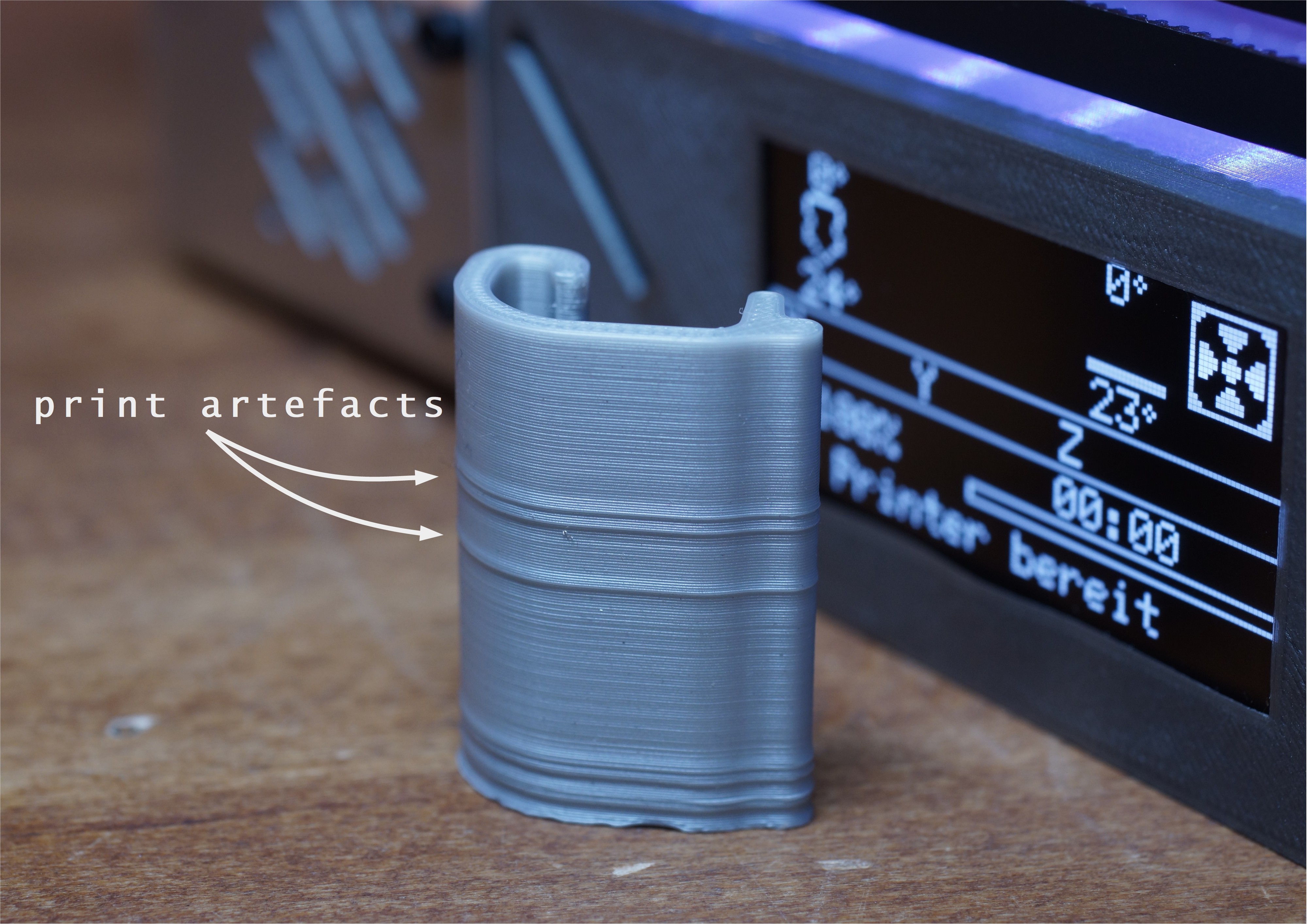
    The print artefacts mentioned in the last log came from the Z-motor, which lost some steps. So I adjusted the motor current. Now this is fixed.

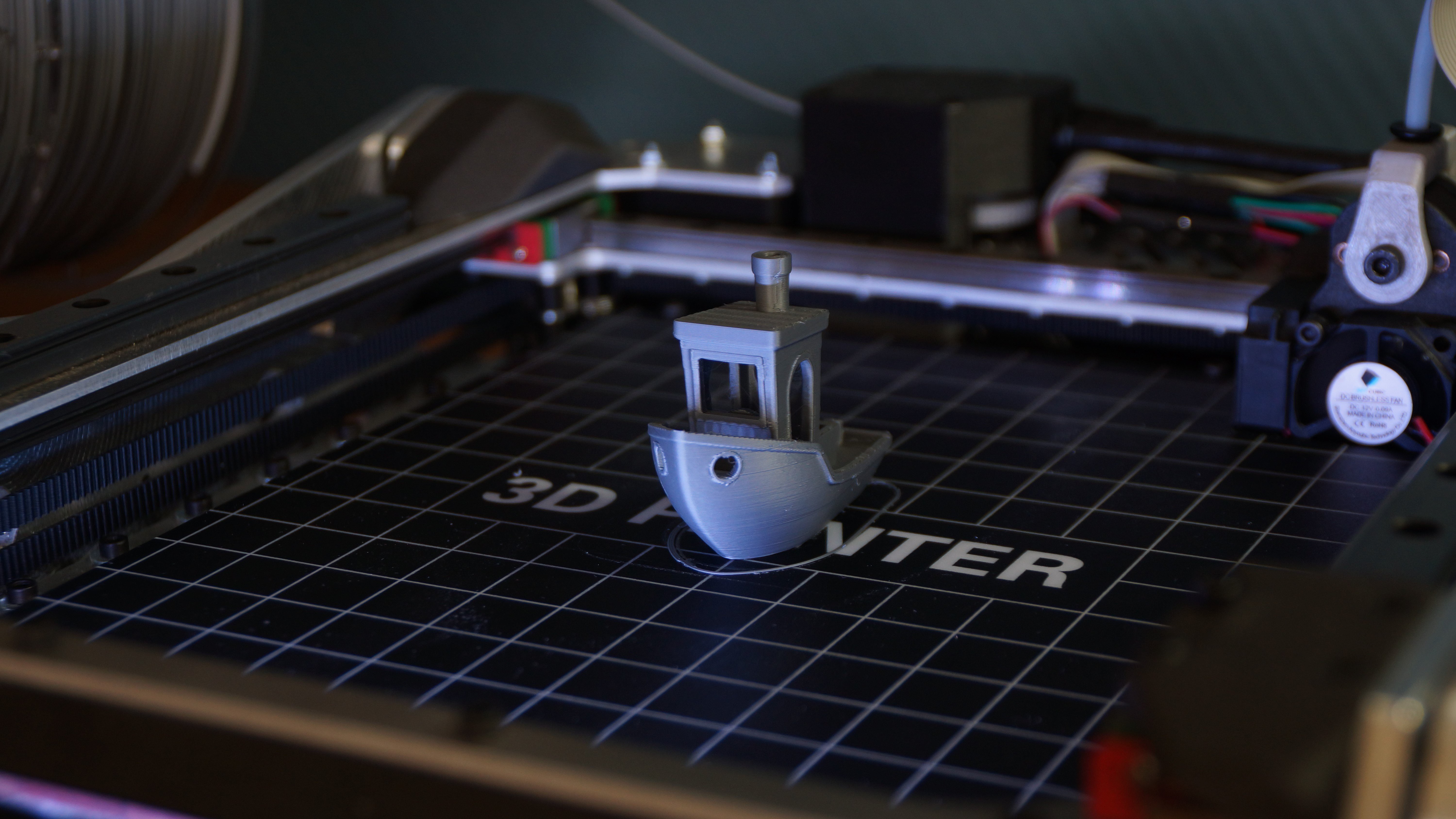
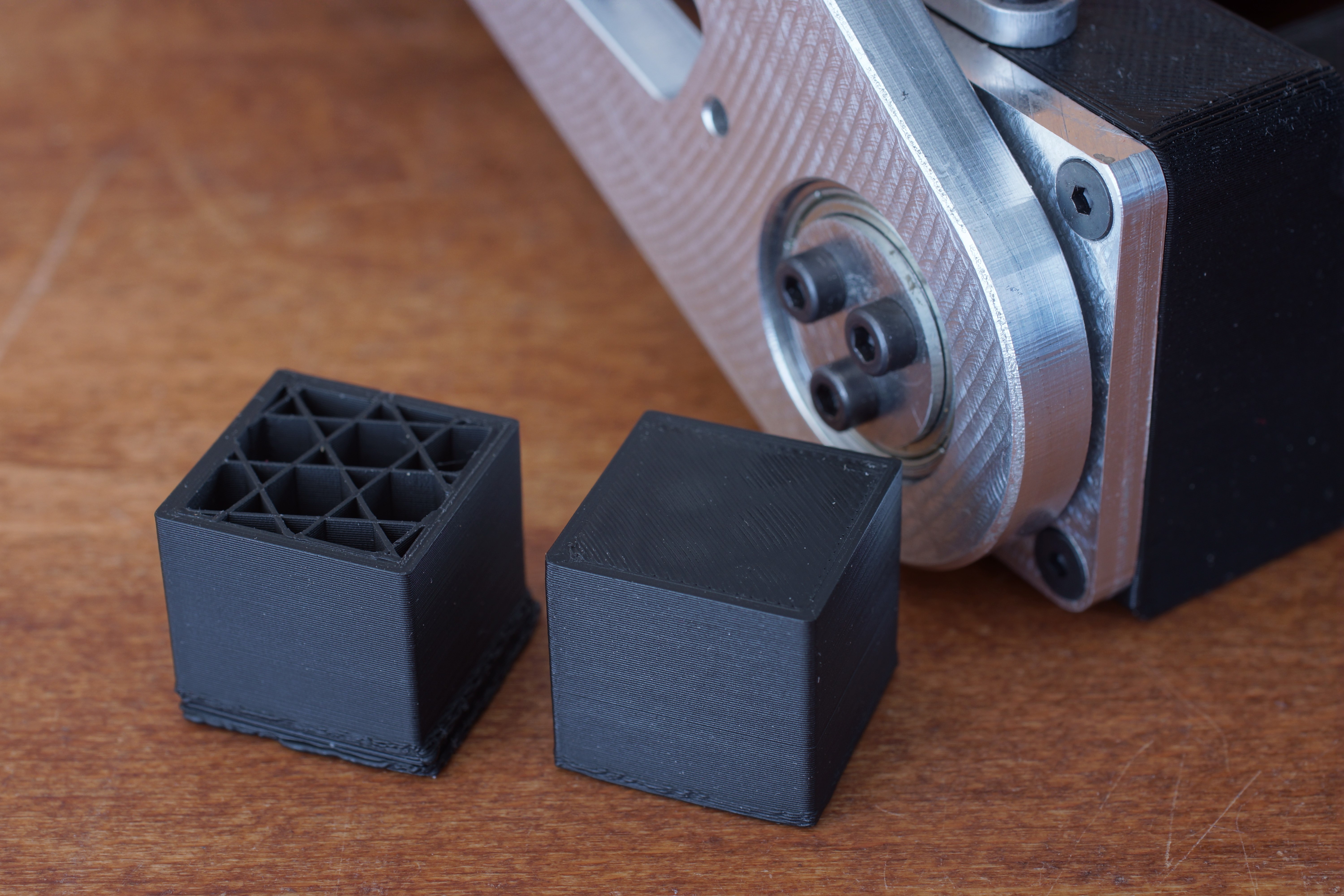
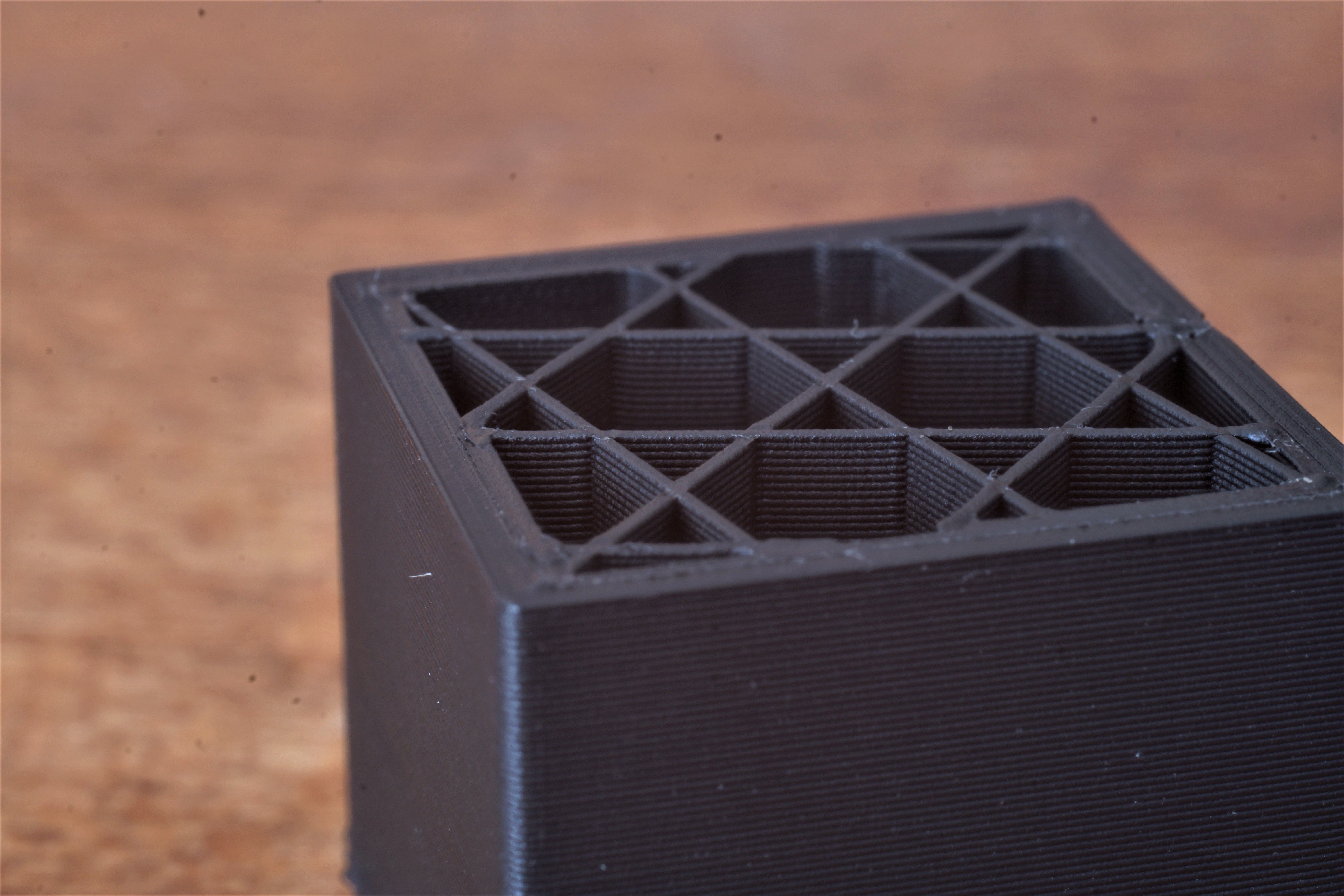
    I printed some 3DBenchys, and the print quality looks very good.

    Layerheight: 0.2mm, print time: 78 minutes
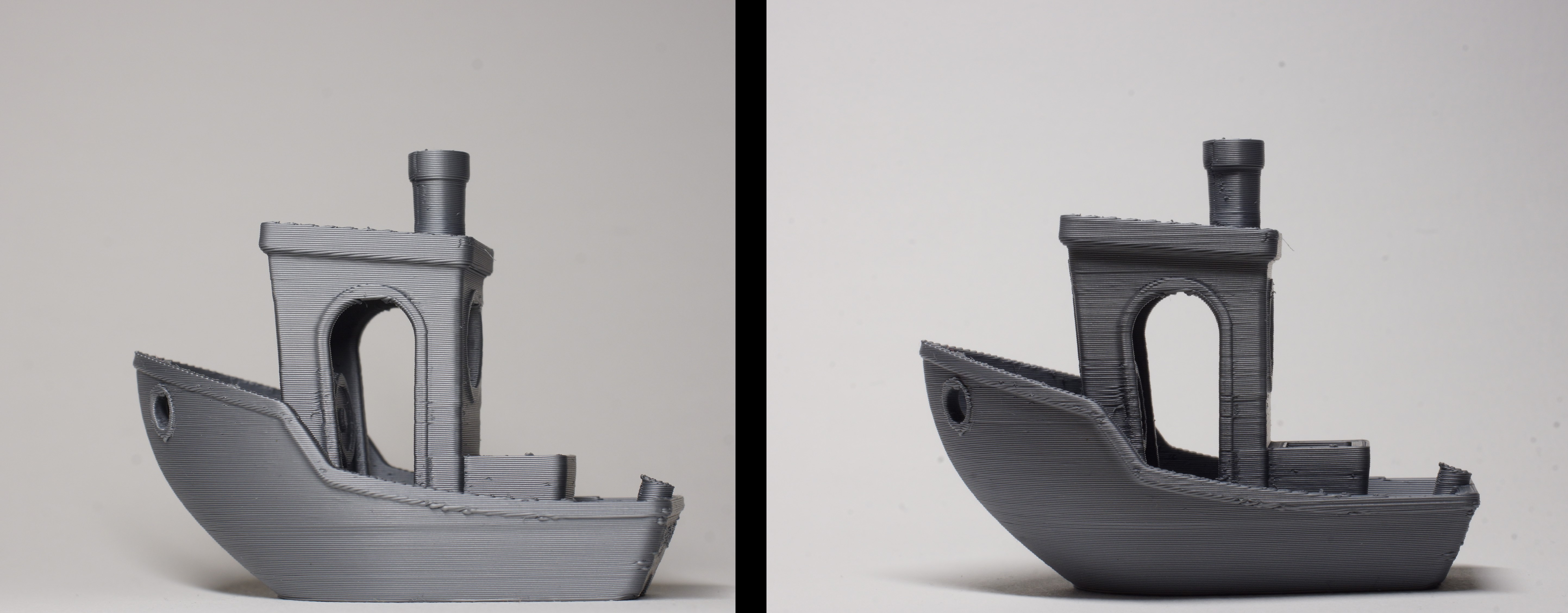

    Quality:
    From some light angles, you can see layer "misalignment". It looks similar to the "error 602" from the Prusa i3.
    https://github.com/prusa3d/Prusa-Firmware/issues/602

    Perhaps it is due to the small difference in filament diameter (+/-0.05 deviation). Or can a mechanical problem be the reason for that?

    Problem Z-homing:

    The biggest problem I'm facing right now is the inaccuracy of the Z-homing.
    When I start several prints one after the other, the distance to the bed for the first layer gets smaller with every print. I don't know what the reason for that is.

    The only things I can imagine are:
    The axial-bearings are frictions ones, so maybe they need some kind of "warming-up" (some movement), so they are working more freely and do not get "stuck" in motion.

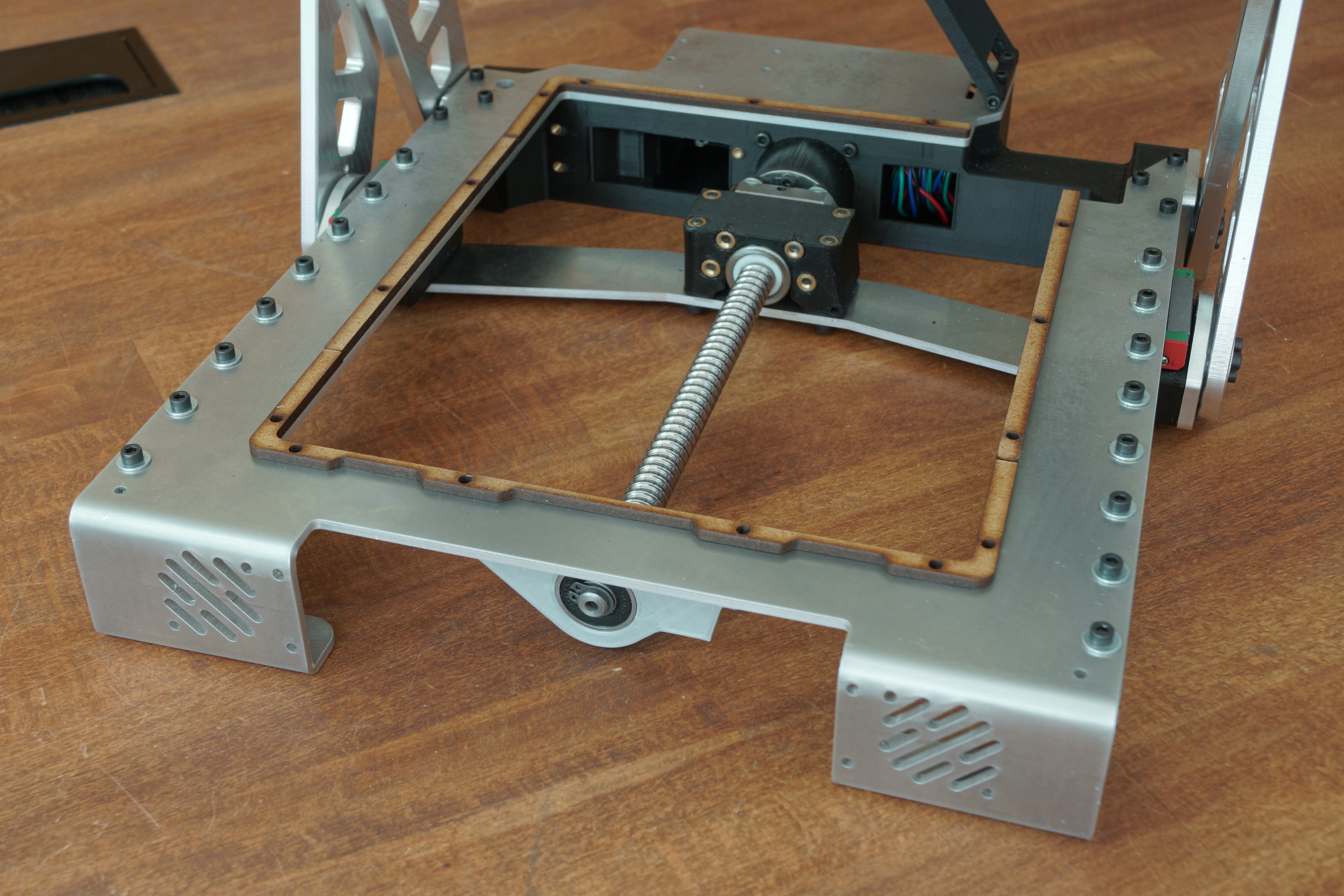
    The second reason I can imagine could be the mounting of the endstop. Right now it is mounted at the bearing-housing of the Ballscrew which is mounted to the frame. The problem is that this bearing-housing moves slightly while the printer is in the folded position and tries to unfold. This makes the homing-process probably more inaccurate.

    The housing moves due to "extreme" forces while the unfolding-process. The forces cause the Z-motor mount to bend slightly.
    Through the bending, the whole assembly (Z-motor, ball screw and bearing-housing) moves a bit towards the front, because these components are all connected the bearing housing moves as well. It would be better if the endstop is mounted truly fixed to the frame(I'll try that next).

    These are my ideas about this problem, but I'm not an engineer. I'm open to helpful comments about that.

    GitHub:

    I uploaded the whole assembly of the X printer(CAD-files) on the Github repository.
    https://github.com/alpha3141/X_printer

  • Update + Problem: backlash

    Malte Schrader12/08/2019 at 23:03 0 comments

    Thanks to Platformio I switched back to Marlin 2 because the compile times are much better than those of the Arduino IDE.

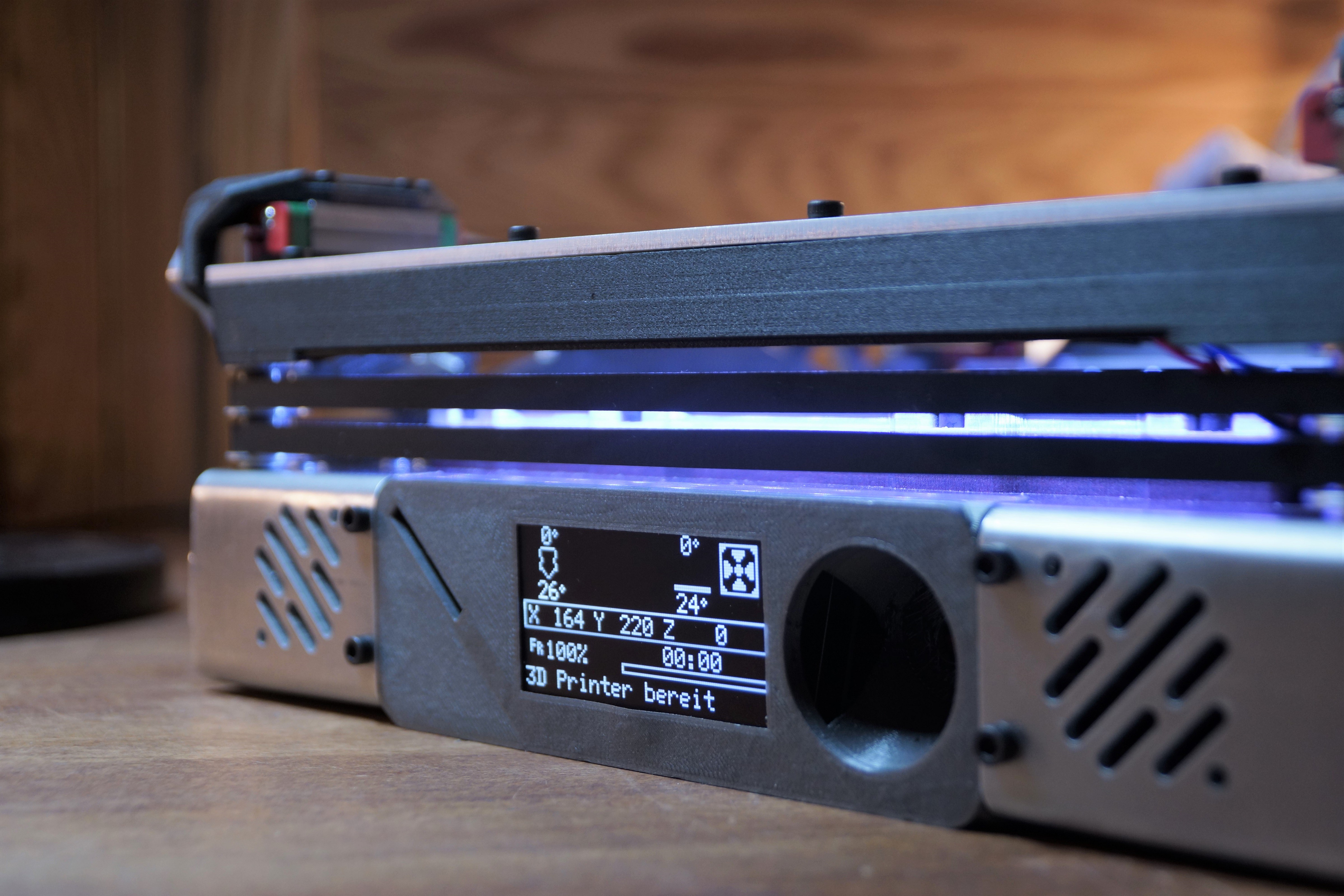
    The printer now has a 12x12cm silicone heatbed, and I was able to install the OLED display.

    The whole display controller assembly (3D-printed part) still needs some modifications because, at the moment, not all components fit.


    Reinforced Z-slider
    I reinforced the Z-slider with another 3mm aluminium plate which I screwed onto the old Z-slider. Unfortunately, my tapped screw threads weren't very precise so that I couldn't use all screw holes to join the two parts together.
    With the new reinforced Z-slider, the printer is now at all Z-heights above the printbed rigid (no Z-flex when applying extra load in Z-direction).
    When The Nozzle moves under the printbed, the Z-flex starts to increase.
    Which for the printing process is unimportant, but can be a problem when homing to Z min (could result in homing position inaccuracy).

    Backlash
    The Z-axis has backlash, which I didn't aspect to happen because the axis has a preload due to the scissor lift and the weight of the upper construction.
    The backlash caused the print artefacts in the first layers, which I mentioned in the last log because the standard PrusaSlicer Gcode moves the printhead at first some millimetres above the printbed before the printer moves downwards and then starts printing.

    To solve the problem, I have changed the Gcode so that after homing, the printer moves only upwards, which is a short term solution, but backlash limits the possible features of the printer. Z-hop and auto bed leveling will be not usable.

     Even homing is hard with backlash, for more accuracy I'm pushing the upper construction manually downwards before homing, to eliminate the backlash.

    I tried the backlash compensation feature in Marlin, but it didn't work very well since the printer moves slightly upwards during the compensation process.
    The next thing that I want to try is to improve lubrication because I think there is already enough preload to prevent the backlash.
    Maybe some of you have any ideas on how to solve that problem.

    Print quality

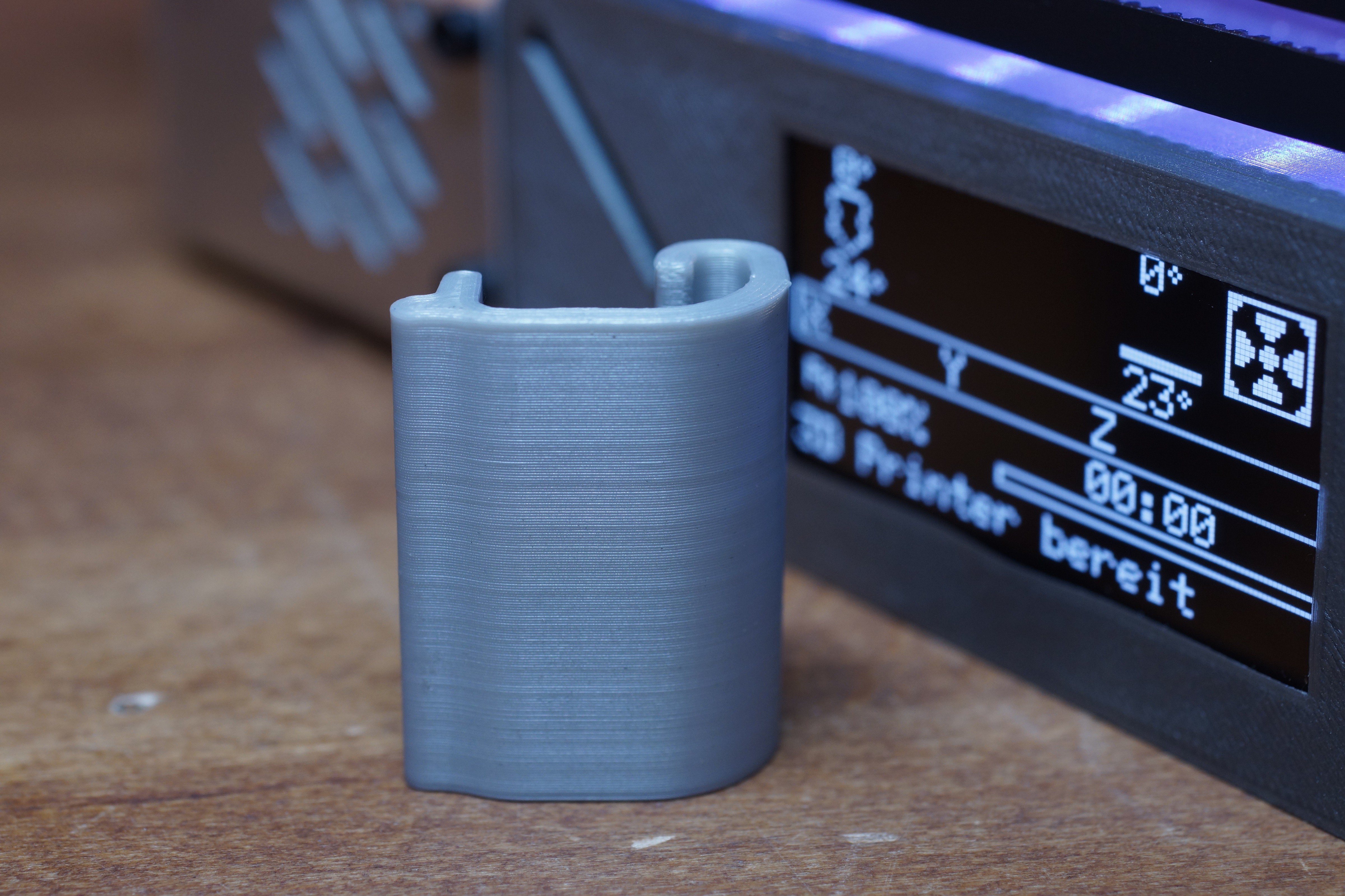
    Print quality looks good. Some test parts are getting weird print artefacts from which I don't know where they come. But I think this is not a Z-axis problem. I increased the belt tensions, which improved the problem. When I print with slower speed, the artefacts are mostly gone. But I'm still not sure what exactly is causing these artefacts. Feel free to write a comment If you have any ideas.


  • wiring done + first print

    Malte Schrader10/15/2019 at 13:29 0 comments

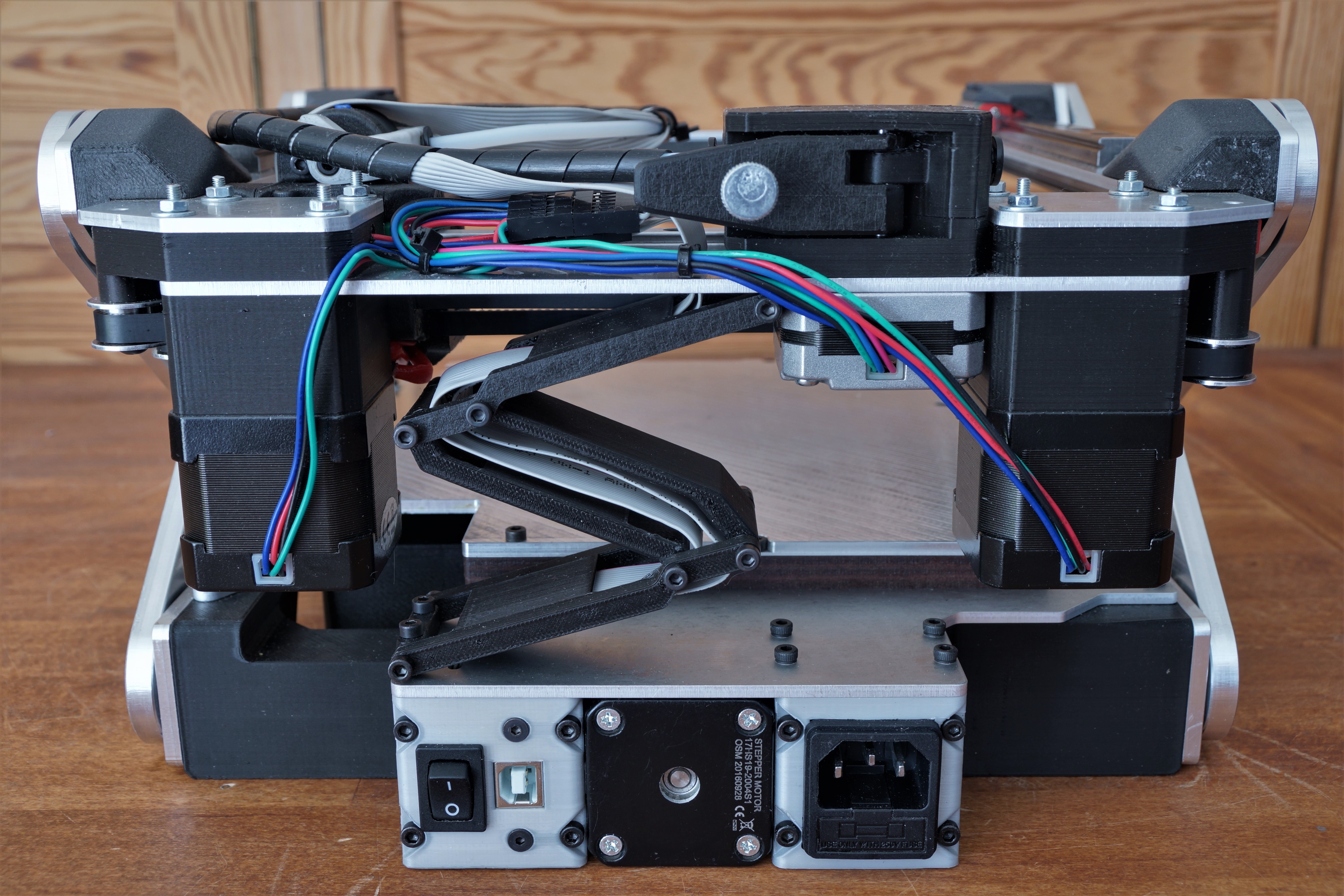
    I managed to wire everything up. It is not the best wire management, but it works. I added a LED-strip at the front for better looks and usability. The power supply and EinsyRambo are mounted under the 3d printer between the Z-slider and the printbed.

    In the back, there are a power switch, a USB-port and a power connection + fuse.


    First print :

    The first prints are looking very promising. I printed the test cubes with a 0.2mm layer height.

    On the other hand, the first layers are still pretty bad.
    I lifted the printbed 6mm as I thought this would improve it, but it didn't.
    Without a heated bed, the print adhesion ist not good, which could be a factor as well. The Z-slider has some flex which leads to some looseness in Z-direction. It is made out of 3mm Aluminum(7075), but it is still not rigid enough. I want to try to reinforce it, maybe this will help.

  • G28 - Homing

    Malte Schrader09/25/2019 at 19:05 0 comments

    Here is a video of the homing procedure. X and Y are homed sensorless and Z with an regular endstop.

    With the help of Uzair Patel I was able to solve the non-linear Z-Axis firmware problem. I decided to use marlin 1 instead of marlin 2, because marlin 2 takes way longer to compile in the arduino IDE than marlin 1.   
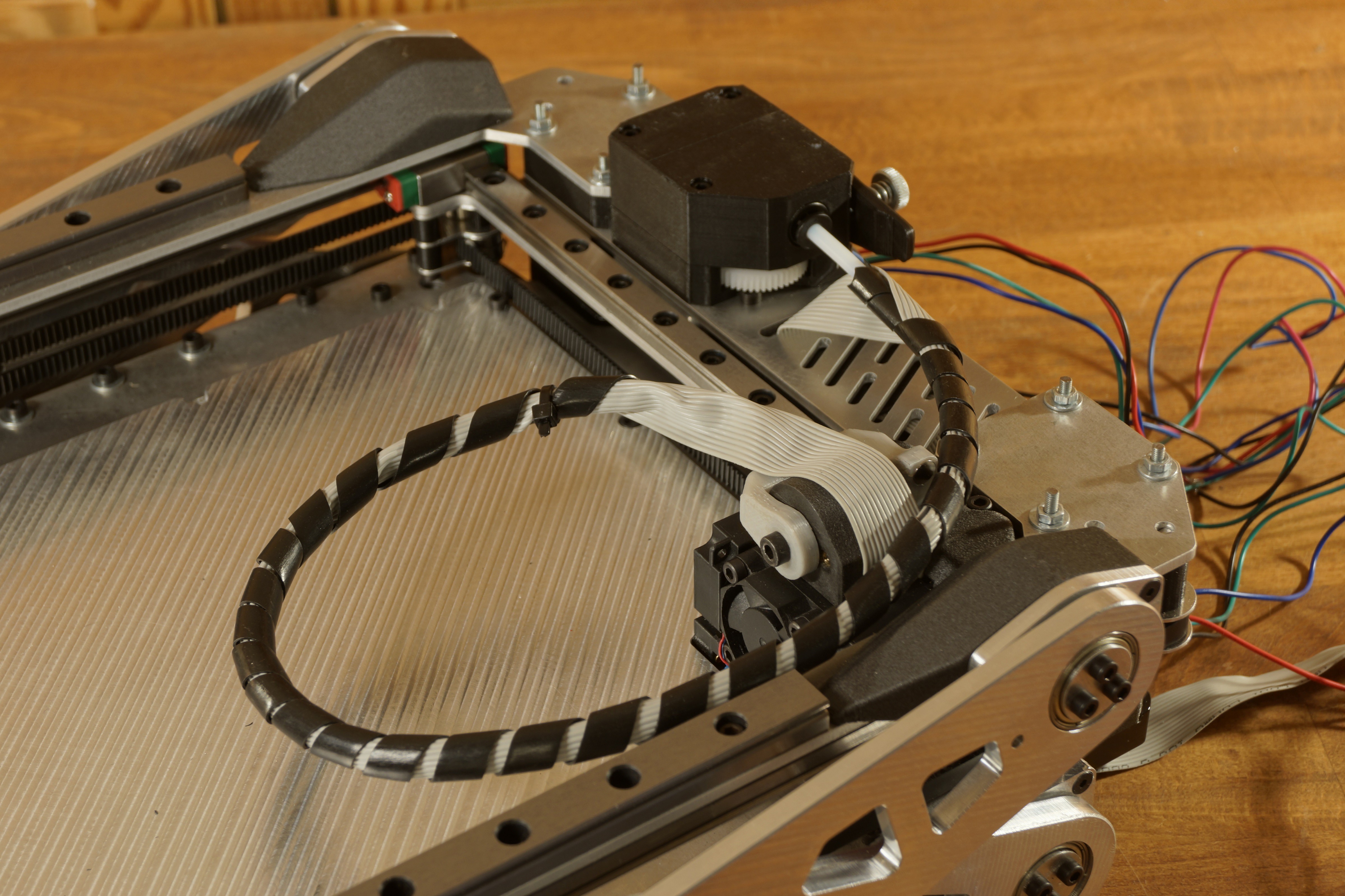
    I added the extruder and the  Bowden tube to the printer.

    And here is a picture of the "folded" Bowden tube.

  • printhead wiring + Bowden tube

    Malte Schrader09/05/2019 at 14:38 0 comments

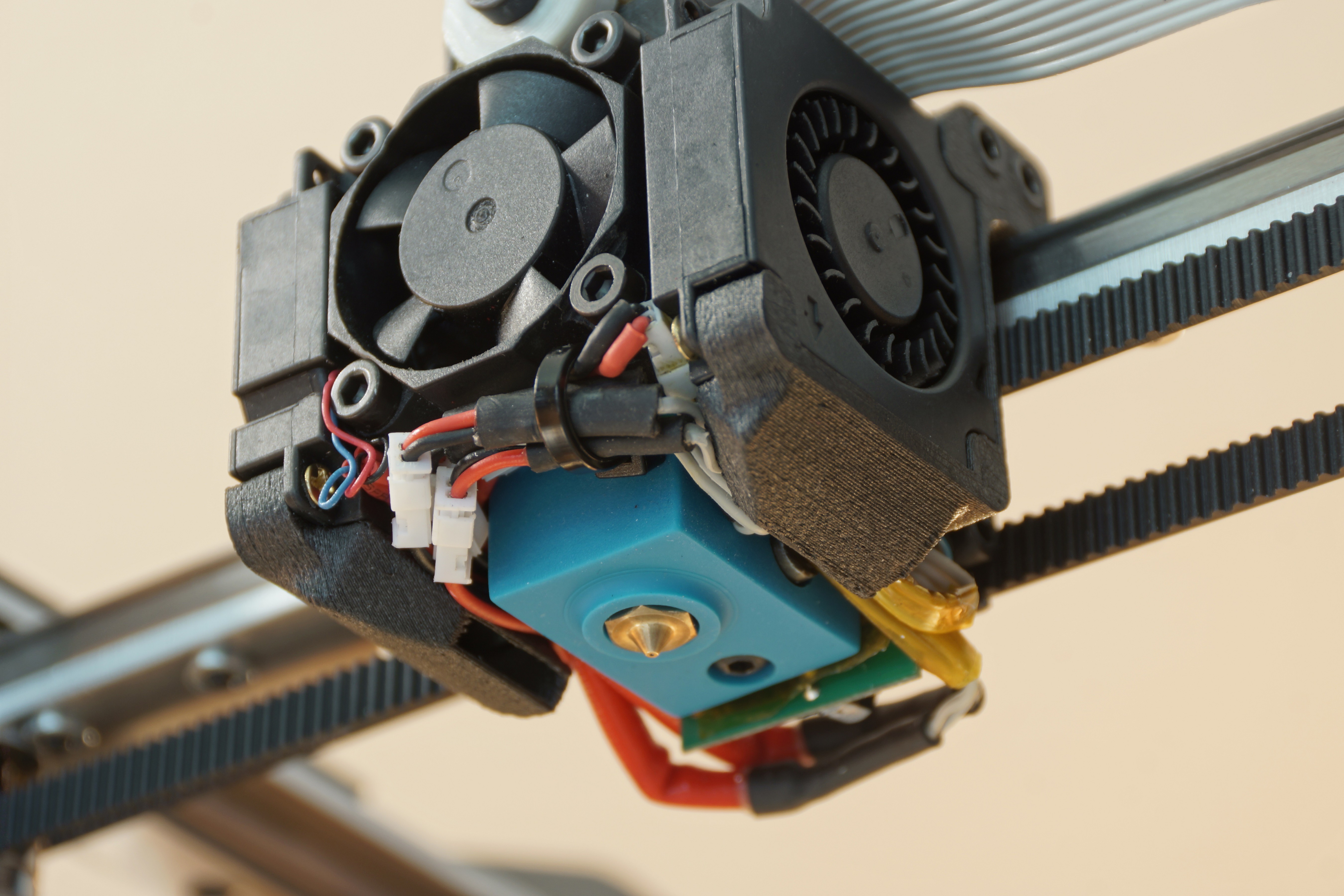
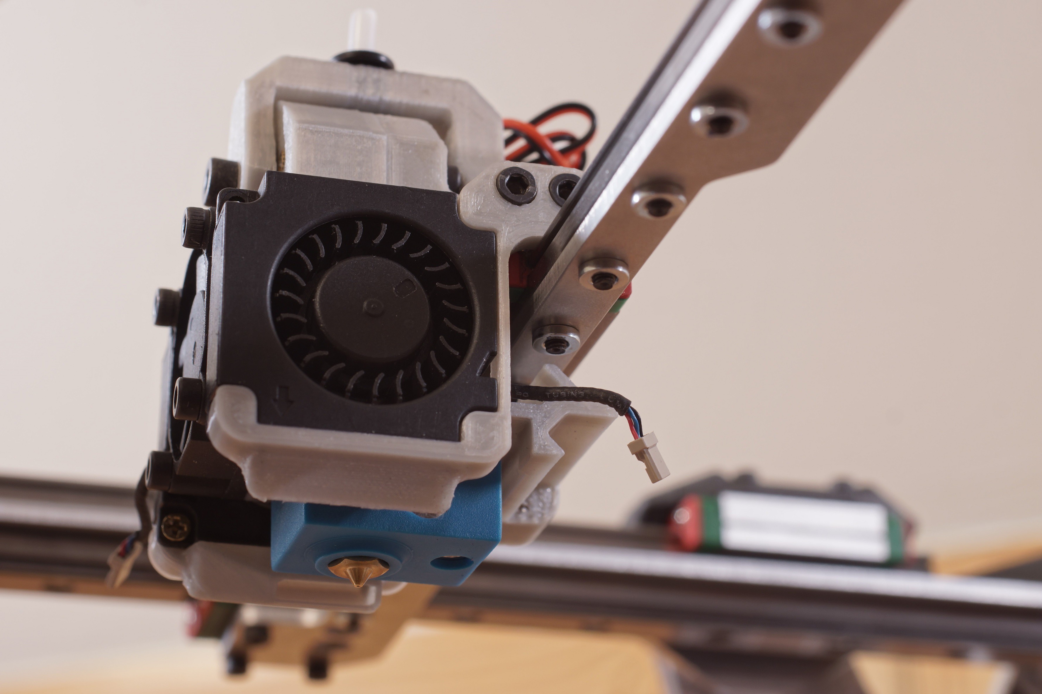
    The final printhead is mounted.

    The wiring of the printhead is pretty tight and very close (too close ?)  to the heat block, but the heat block has a silicone sock, so I hope everything will work fine. 

    The Bowden tube is foldable mounted to the printhead for maximum portability.

  • printbed

    Malte Schrader09/02/2019 at 19:12 0 comments

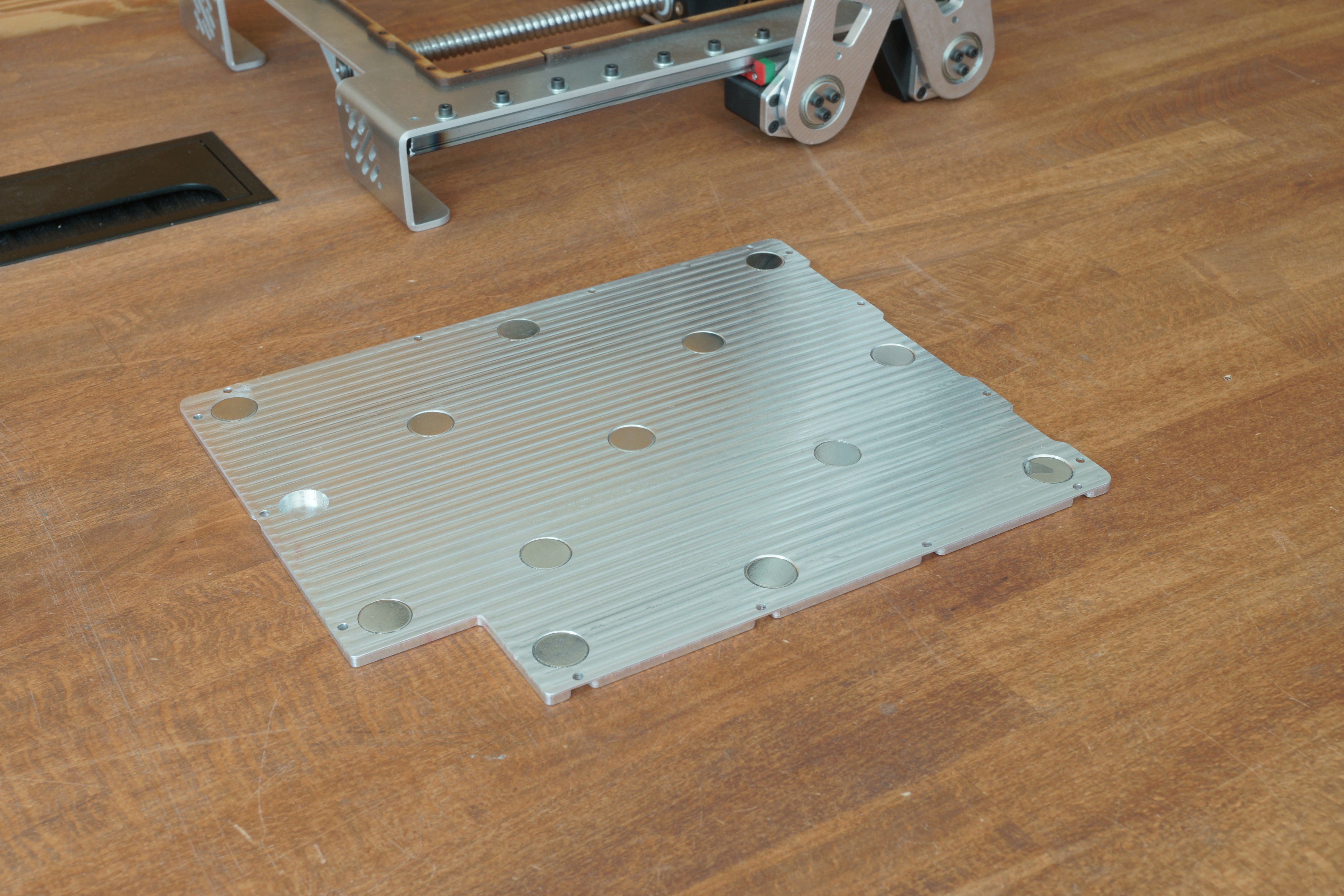
    I machined the printbed. 

    On the bottom side are holes for high-temperature magnets which are required for the removable printbed. At the rear right corner is a cutout for the printhead, because the nozzle needs to be below the print surface so that different nozzles or print surfaces can be attached. Later I want to add a heatbed, but because of the cutout in the printbed, I can't use a standard one. I plan to build one by my self out of copper tape and capton tape. 

    I use 3mm MDF to insulate the printbed from the base frame.

  • belts

    Malte Schrader08/25/2019 at 12:58 0 comments

    I used standoff nuts to mount the pulleys to the X-axis. For this reason, I had to modify my Y-axis carriages with an angle grinder.

    Because of a small mistake in the design process, I had to modify the mounting screws so that the belts have enough space to work properly.


  • X-axis and Y-axis

    Malte Schrader08/24/2019 at 23:28 0 comments

    The X/Y-construction is done. I printed the parts for the printhead (prototype). The printhead has a V6 hotend, two 35mm radial fans for part cooling, and an IR sensor for auto bed levelling. The printer will use a bowden system where the extruder sits next to the left corexy-motor.


    printhead

  • first movement

    Malte Schrader08/22/2019 at 16:54 0 comments

    All sidearms are mounted. The main structure is almost done.
    In the video, you can see the folding process, which looks very promising.
    The printer weighs already 4,3Kg, but the aluminum parts pay off because the construction is quite rigid.

View all 11 project logs

Enjoy this project?

Share

Discussions

masvatk wrote 01/28/2023 at 16:26 point

marlin2.0的Z轴怎么修改,可有人知道??不想用1.0。

  Are you sure? yes | no

murithemyth wrote 07/03/2022 at 02:30 point

Wow! How much do the printer weigh in the end

  Are you sure? yes | no

negative3kelvin wrote 03/22/2021 at 07:59 point

Here's someone else's attempt, and they used springs on the scissor joints to possibly overcome the higher force needed to lift from Z @ 0.  http://www.digitaljournal.com/pr/4547519  Not sure if that would exacerbate backlash though.  Any new developments?

  Are you sure? yes | no

Malte Schrader wrote 04/09/2021 at 10:57 point

I had paused the project for a while. But now I wanna build a second version. Couldn't find much information about the printer which you linked, but springs can be helpful.
The goal for the second try is to lighten the printer, minimize it a bit in all dimensions and use 3mm flat aluminium parts instead of CNC milled ones.

The targeted height for the second one is 7 cm (folded). Does anyone have suggestions for the other dimensions of the printer?
Haven't yet decided what outer dimensions are practical

  Are you sure? yes | no

jlipavsky79 wrote 03/26/2020 at 20:20 point

is there any hopes of you posting these files soon?

  Are you sure? yes | no

Malte Schrader wrote 03/29/2020 at 09:28 point

The CAD-files are already published. https://github.com/alpha3141/X_printer

  Are you sure? yes | no

slavon782 wrote 03/22/2020 at 14:45 point

Hello!!! How you do it ???? "

Update: This problem has been solved. I added the formula for the non-linear Z-axis to the firmware.

"

Thank you.

  Are you sure? yes | no

Malte Schrader wrote 03/29/2020 at 09:40 point

You can read more about that in the public chat of this project where Federico Virdia asked the same question. 

  Are you sure? yes | no

DJ Rozwick wrote 10/27/2019 at 16:00 point

Great idea.  I am curious of the precision in the lift.

  Are you sure? yes | no

Shawn wrote 10/24/2019 at 01:57 point

I am beyond impressed that you got that to work. I had thought that a scissor lift style printer was impractical. I'm a little envious :) I hope that some of the members can be 3d printed on a larger machine first rather than needing to use milled aluminum.

  Are you sure? yes | no

Addison Woods wrote 10/14/2019 at 06:12 point

so hyped for this! do you plan to release the files for the aluminium milled version, or just the reprap friendly version?

  Are you sure? yes | no

Malte Schrader wrote 10/15/2019 at 13:37 point

I will publish the files for this version as well.

  Are you sure? yes | no

sanju71 wrote 10/06/2019 at 11:43 point

Very inspiring and innovative design... Especially the adapting of the open source resources.. Impressive. Keep up the great work... Being a trained Biotechnologist I am learning from you guys... to get acquainted in newer technologies. Thanks. 

  Are you sure? yes | no

D.77 wrote 10/04/2019 at 09:11 point

Interesting project and then embracing the open source concept is even more appreciable :)

  Are you sure? yes | no

Madaeon wrote 10/03/2019 at 08:07 point

This is a nice project and good implementation. I have been working on this principle since 2014 (mainly for resin 3d printing, https://www.lumindustries.com/the-new-lumifold), and got a patent for this system for my startup (I am the designer/developer/firmware writer/tester). Currently I have a prototype working quite well, not yet on the market anyway.   And yes, the Z axis being non linear is a bit difficult, especially if the machine is super compact so you have very tight spaces for encoders or sensors. And with resin, tolreances are even smaller.

  Are you sure? yes | no

sanju71 wrote 10/06/2019 at 11:45 point

Curious to know more about your undertakings & work 

  Are you sure? yes | no

tormentor22 wrote 09/30/2019 at 18:20 point

Would there be a builing guide and a complete BOM? 

  Are you sure? yes | no

Malte Schrader wrote 10/01/2019 at 19:03 point

yes definitely, but I think not in the near future because this takes a lot of time to set up.

  Are you sure? yes | no

OpenDev wrote 09/25/2019 at 16:22 point

WoW great design!!! i thinking about build one for hackathons :)

  Are you sure? yes | no

Uzair Patel wrote 09/04/2019 at 09:41 point

  Are you sure? yes | no

Malte Schrader wrote 09/04/2019 at 12:19 point

Thanks

  Are you sure? yes | no

sanju71 wrote 10/06/2019 at 11:48 point

Fantastic & motivational openness. 

I wish to build my own 3d printer...but probably I need to wait for another year or so, before I start earning after my schooling. 

  Are you sure? yes | no

rraetz wrote 08/24/2019 at 10:02 point

Great idea, I love it! 

  Are you sure? yes | no

Similar Projects

Does this project spark your interest?

Become a member to follow this project and never miss any updates