 Steven
-
1Introduction to and Basic Overview of the Project
Project Albatross was developed in response to the greatly heightened need for water quality monitoring in the world today. With the looming threat of climate change, the rising of the oceans, ocean acidification, the rampant spread of plastic pollution in water bodies, and other harmful environmental issues, it is more important now than it ever was for us to understand the health of our water bodies so that we can help fix the issues they face.
Using robots to take water quality measurements is not exactly a new concept. Autonomous underwater vehicles (AUVs) such as REMUS and various underwater gliders have been in use since the early 2000s, with the designs for these vehicles, in some cases, being proposed much earlier. However, while these robots work spectacularly for their intended purposes, they contain multiple limitations. The first is that they are typically very expensive and only used by a select cohort of research institutions that either developed them or have the exorbitant budget necessary to purchase them. Smaller research institutions or companies (such as universities with smaller budgets, marinas, nonprofit wildlife societies, etc.) often do not purchase these robots for this reason, and instead rely on old fashioned manual data capturing instead.
Manual data capturing involves a crew of people going out on a boat to manually drop a CTD module (conductivity, temperature, and depth sensing module) to different depths at various locations, which of course is more costly and time consuming than using a robot for data capturing. In addition, as manual data capturing takes more time, scientists taking manual data often space out the locations at which they take their samples greatly so that they can cover larger areas in a reasonable time frame. This wide spread between data points leads to very sparse datasets being produced, which often suffer from the effect of aliasing when they are used to discern trends in the measurements. Finally, manual data capturing leads to mainly vertical profiles being taken of a water body, as the CTD devices are more easily dropped vertically to different depths at a given location than they are dragged horizontally from location to location. This solely vertical profile of a water body leads to potential gaps in knowledge and information when trying to determine trends in the water measurements.
Going back to the current robot applications themselves, it is evident that underwater vehicles (AUVs and underwater remotely operated vehicles [ROVs]) provide superior measurements as they can capture data over a large range of depths (sometimes up to thousands of meters). By contrast, another class of vehicles known as surface vehicles (autonomous surface vehicles [ASVs] and surface ROVs) are basically boats that only move and collect data at the water's surface. However, while AUVs provide better measurements, the fastest and most well-developed form of wireless communication, radio frequency (RF) communication, does not work underwater. As such, most AUVs have to surface at multiple points throughout a given mission to relay information wirelessly back to a ground control station. This surfacing wastes precious time and energy, and prevents any real-time analysis of data from occurring. ASVs can, of course, use radio communication always since they operate at the surface. Such a trade-off between measurement capabilities and the ability to perform real-time radio communication with a ground control station motivates the idea for a combined ASV-AUV system that highlights the advantages of both approaches.
We are by no means the first group to propose a combined ASV-AUV system. Our research produced information about a few other groups who have tried to develop similar designs (https://ieeexplore.ieee.org/document/5509187, https://www.liquid-robotics.com/wave-glider/how-it-works/). However, we wanted to develop a low-cost, open source, fully modular, and intuitive to use system that included custom construction, hardware design, and software design. Our goal was to produce a system that could be built and used by anyone for under $1500 to motivate smaller groups around the world to begin taking pertinent water quality measurements with greater accuracy and ease. Thus, Project Albatross was born.
The basics of the system's design are as follows.
-
2Building the ASV
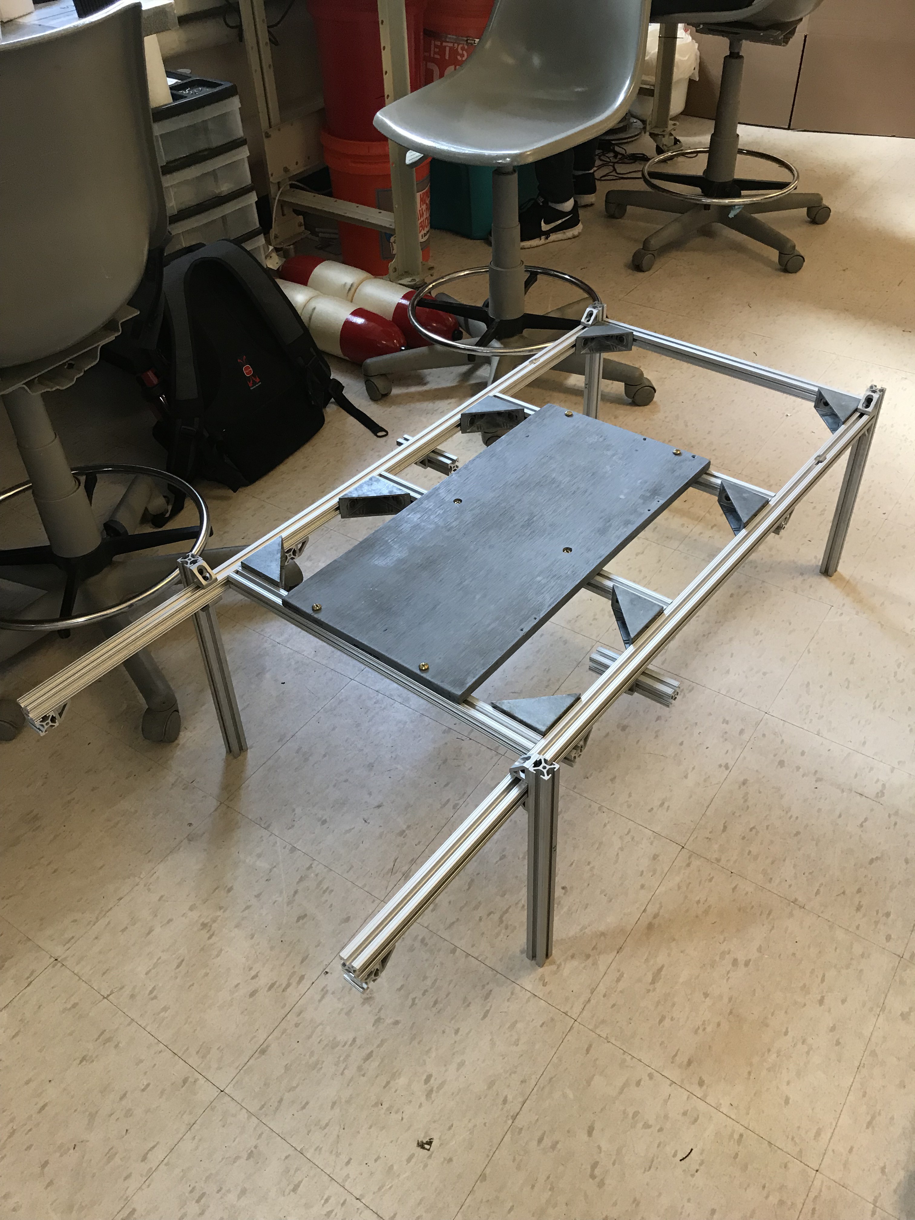
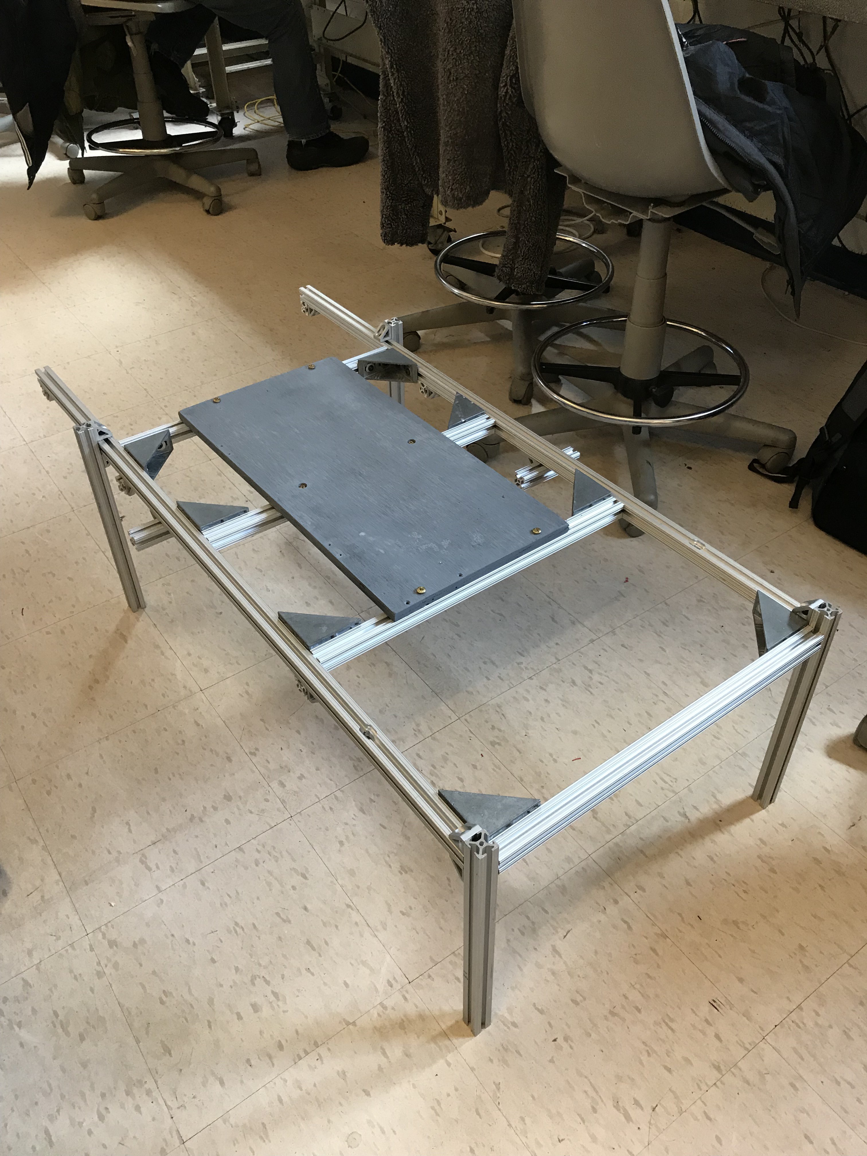
To build the frame for our autonomous surface vehicle (ASV), we utilized T-slotted aluminum extrusion. Aluminum was the perfect choice for our vehicle frame as it is lightweight, strong, relatively low cost, and resistant to corrosion and rust. T-slotted aluminum bars allowed us to build our frame without any welding or specialty power tools. This was key as our frame design changed a few times throughout the project as we iterated through different motor positions and frame features, so we were able to unscrew joints and move the frame bars with relative ease.
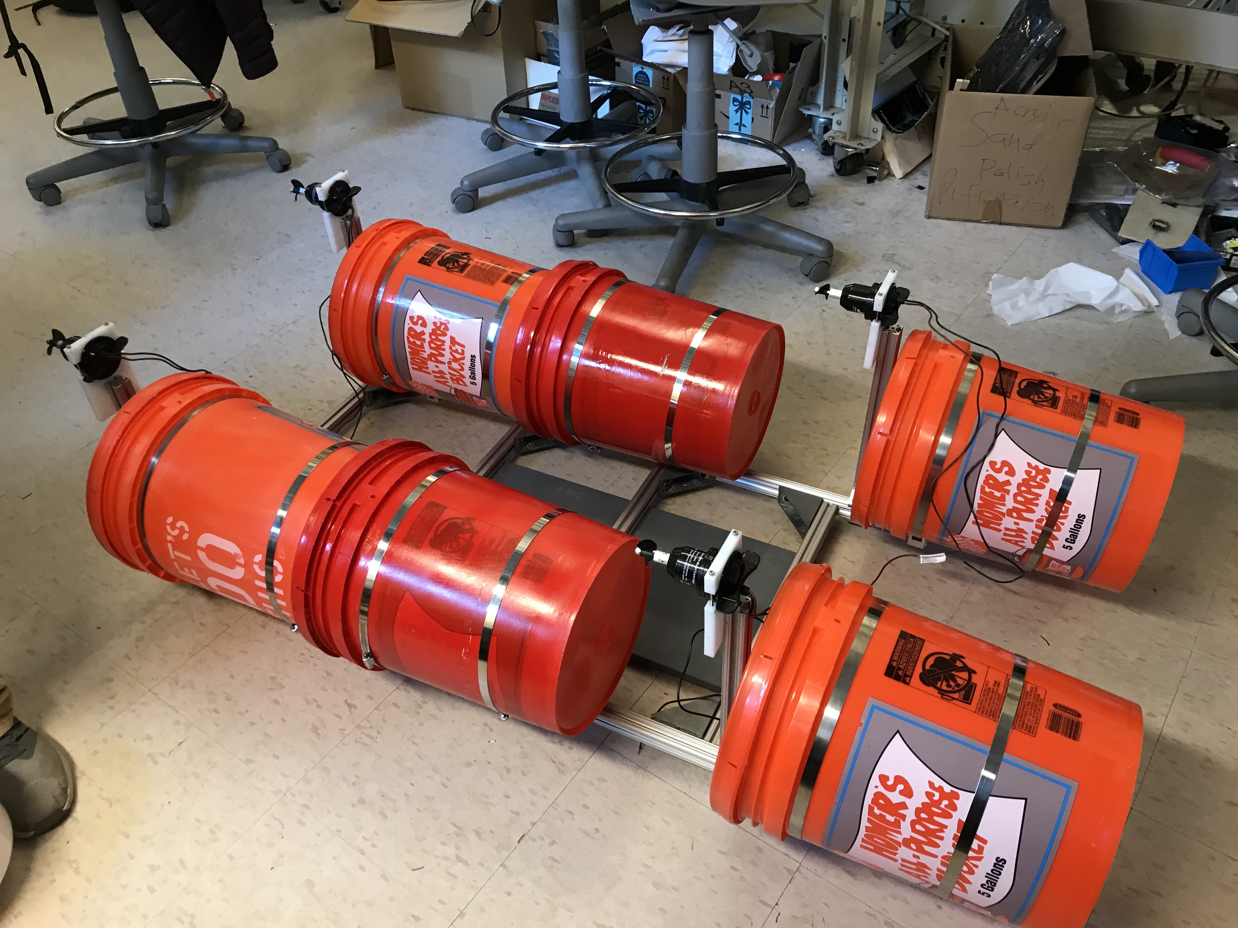
Our frame design was intentionally simplistic as this made the surface vehicle easy to construct without sacrificing performance. The frame was about 4 feet in length and 2 feet in width, with 4 crossbars for support and 6 vertical bars for mounting the 6 motors used by the vehicle. The crossbars were connected to the frame's sidebars using heavy duty corner brackets, while the remaining joints that needed less support were connected with small 1'' x 1'' corner brackets. A wooden board was screwed into the middle three crossbars to support the main electronics housing.
![]()
![]()
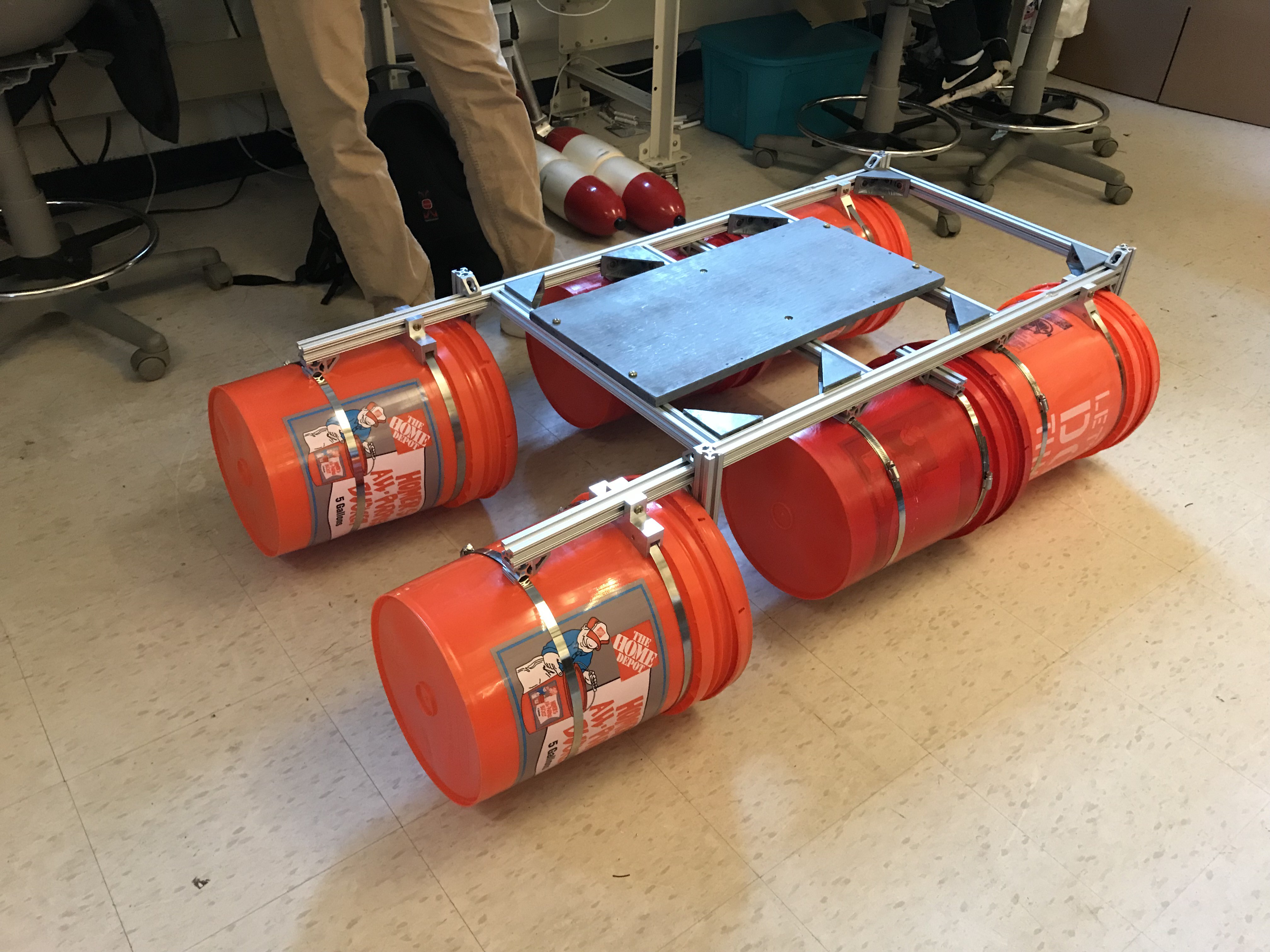
From here, 6 Home Depot five gallon buckets with Leakproof Lids attached were used to provide flotation for the frame. The lids were sealed to the buckets using a marine sealant produced by Sudbury Boat Care known as an Elastomeric Sealant. This sealant is designed for applications above and below the waterline and advertises that it provides superior adhesion to polyethylene plastic (which the buckets are made from). Once the sealant cured for 24 hours to secure the lids to the buckets, the buckets were attached to the frame using 12'' steel duct clamping and custom T-slotted aluminum fittings.
![]()
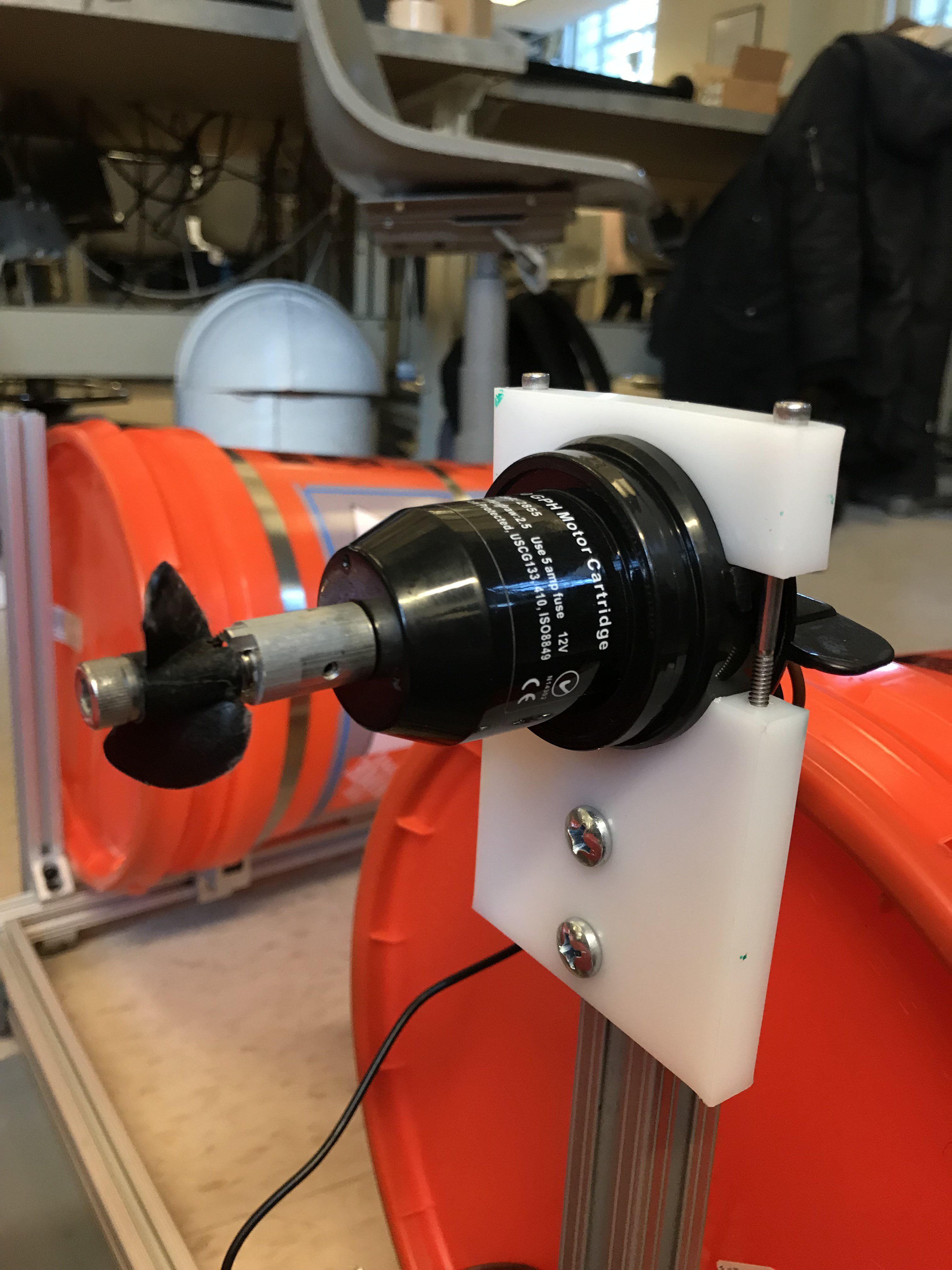
The motors were then attached to the vertical frame bars using custom-cut acrylic mounts. 500 gallon per hour bilge pumps were used for the propulsion motors. 6 motors were used in the design (four are shown in the pictures here, but two more were added later), and all were mounted facing the stern of the vehicle.
![]()
![]()
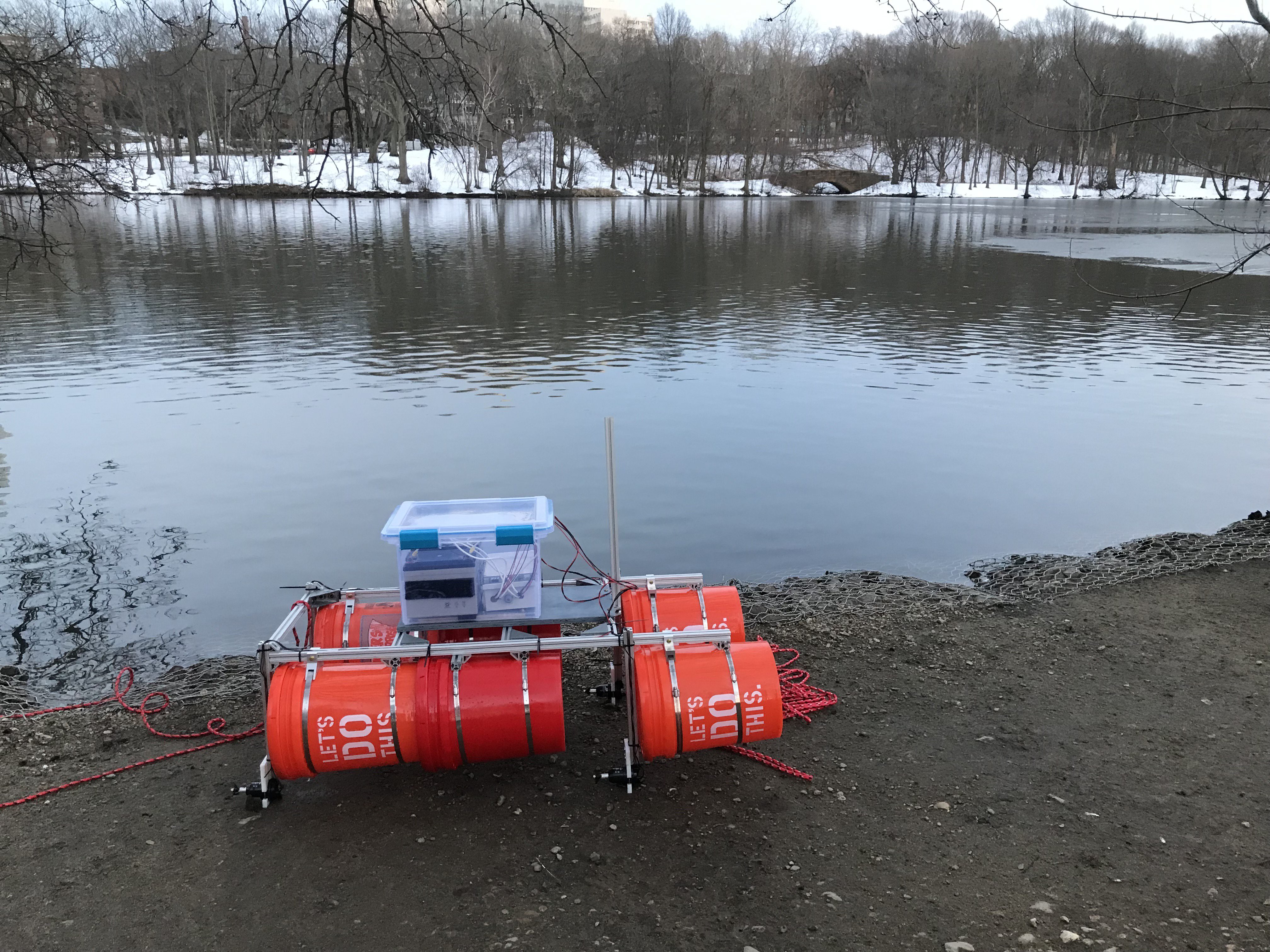
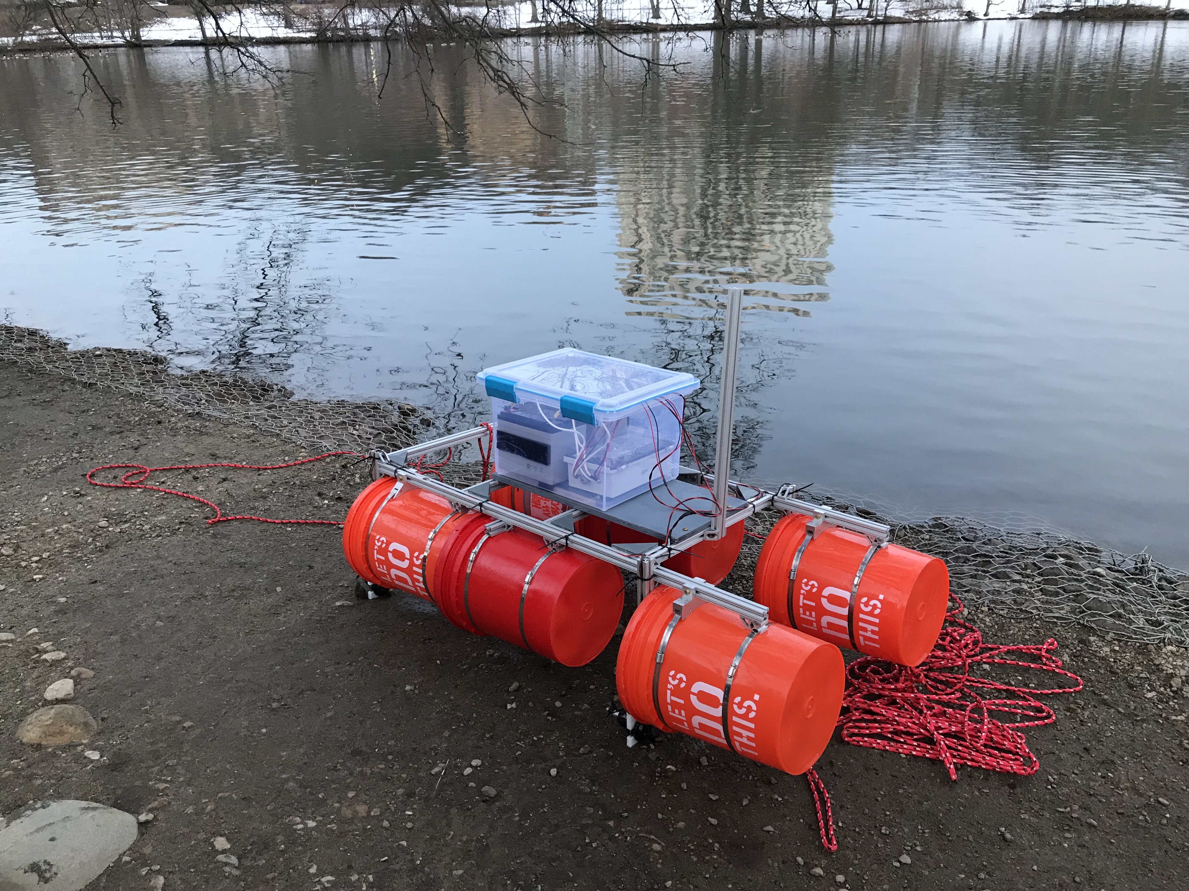
A 32 Qt. Sterilite Gasket Box served as the main electronics housing for the vehicle. We secured it to the wooden board by simply drilling four holes in its bottom and screwing it into the board. Placement of the box was key here, as we wanted to make sure that the vehicle would still sit balanced in the water once the heavy electronics (mainly the batteries) were placed into the housing. A smaller waterproof electronics enclosure was also used for the more delicate electronics (the Pixhawk and Raspberry Pi). A long T-slotted aluminum bar was added to the front of the vehicle facing vertically upwards to mount the radio antenna onto. Two T-slotted aluminum bars of about 18'' in length each were added off the stern of the vehicle for the future tether connecting the ASV to the AUV to attach to. Zip ties were used to secure the motor wires to the frame.
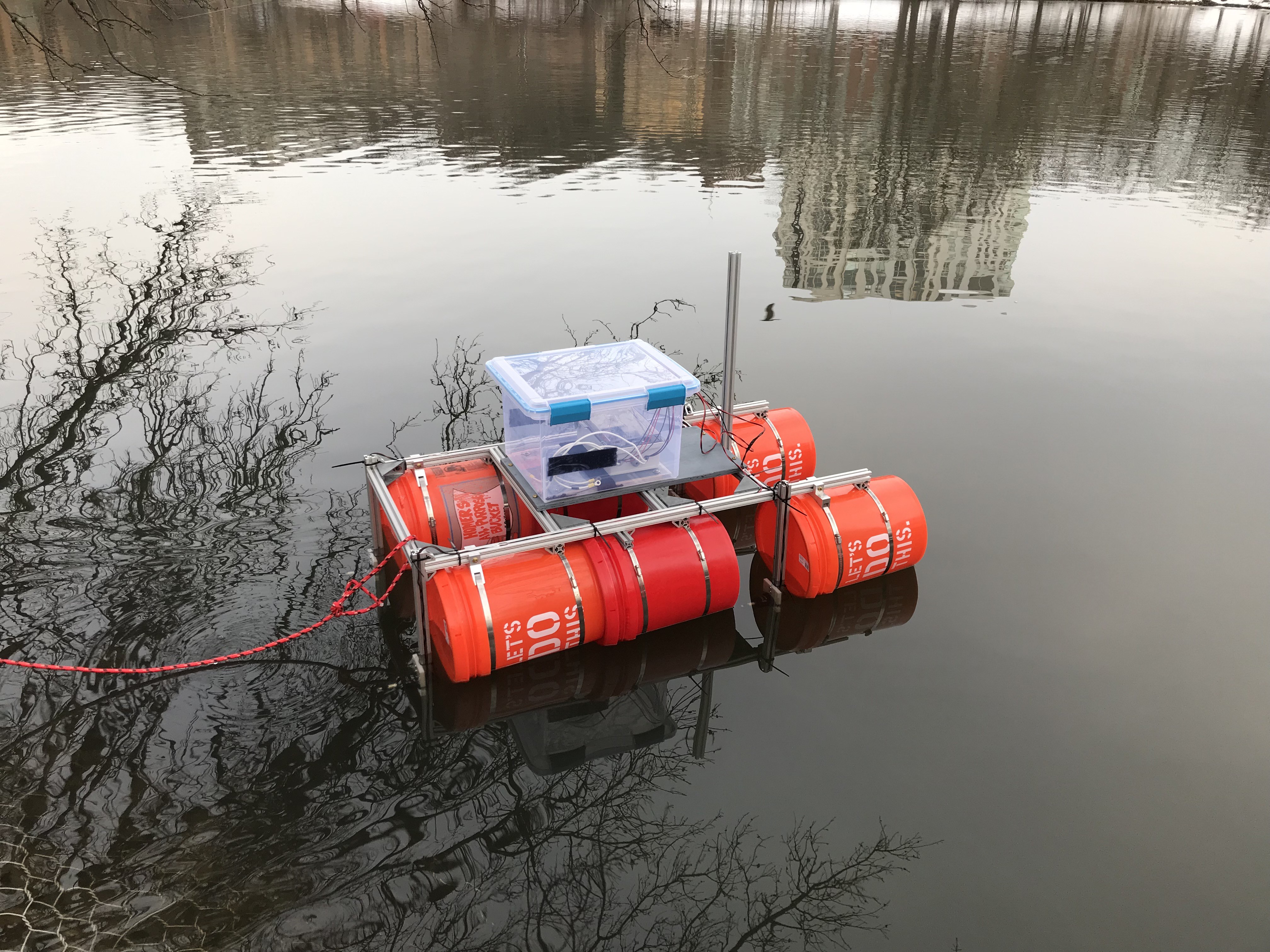
The images below show our surface vehicle in its first flotation test. It was a great success! The vehicle sat balanced in the water as hoped and was able to support the major added weight of the two 12 V 35 Ah sealed lead acid rechargeable batteries that would be used to power the motors. Our construction efforts and buoyancy calculations paid off!
![]()
![]()
![]()
![]()
-
3Configuring the Pixhawk to Correctly Run the Motors
Once the ASV was built, the next main step was to configure the Pixhawk for our application. As the Pixhawk would be autonomously controlling the ASV, it would act as a Rover styled robot. Therefore, we downloaded ArduRover firmware to the Pixhawk and configured it to be a "boat" rover using the Mission Planner software. We chose Mission Planner as our ground control station as it contains the most functionality for configuring and monitoring the Pixhawk-controlled robot and also has the most development support online. Mission Planner can be installed from here http://ardupilot.org/planner/docs/mission-planner-installation.html. An example of the Mission Planner mission monitoring screen (the "Flight Data" screen) where the robot mission can be monitored in real time is shown below.
![]()
The main configuration tasks were performed in the "Initial Setup" and "Config/Tuning" tabs. Some of the steps included setting the robot's yaw angle to be controlled using skid steering (http://ardupilot.org/rover/docs/rover-motor-and-servo-connections.html), setting the type of motor to be "Brushed with Relay", and assigning which pins would be used to control the left and right motors, respectively. For our application, the bilge pumps act as simple brushed motors that we would control using a no-frills motor driver capable of dedicated forward and reverse motion and of sustaining the necessary current (up to 3A per bilge pump, as determined through empirical testing with the pumps). We settled on a HiLetgo BTS7960 motor driver (link given in the components list) and chose to use one to control the left 3 motors and a second to control the right 3 motors. This was made possible through the use of a skid-steering steering control configuration and through the high current limit (43A) of each motor driver.
While it might seem trivial, it took us some time to figure out how to configure the Pixhawk properly to expect regular, brushed motors with separate forward and reverse control. This is because the Pixhawk is mainly targeted towards DIY drone users, who most often use brushless motors controlled by fancier ESCs (electronic speed controllers). As such, much of the online documentation that discusses setting up the Pixhawk talks about properly connecting ESCs and using Mission Planner commands to have the ESCs self-calibrate themselves. If you're just trying to control brushed motors, the configuration documentation really just barely skims over how to do so. To save from future digging, make sure you just set the MOT_PWM_TYPE parameter to "Brushed With Relay" and then assign two motor pins to "Throttle Left" and "Throttle Right" respectively (SERVO3_FUNCTION = 73 [Throttle Left] SERVO1_FUNCTION = 74 [Throttle Right]).
In this mode, the Pixhawk expects that an external relay will be used to flip between forward and reverse motion. Thus, it expects that (as is the case with our motor driver), one pin on the driver is used to drive the motor forwards and a second pin is used to drive the motor backwards, with the same positive pulse PWM signal being sent. The pins used by the Pixhawk for relay control are auxiliary pins 5 and 6. If desirable, you can configure in Mission Planner which relay controls which motors' directions (the throttle left or throttle right motors) by modifying the RELAY_PIN and RELAY_PIN2 parameters in the Config/Tuning tab under the Standard Params. We will go over how to connect the circuitry for the motor control next.
-
4Connecting the ASV Motor Circuit
To connect the bilge pumps to properly to the Pixhawk, we had to implement a circuit including two relays, the two HiLetgo BTS7960 motor drivers, two buffer circuits, and three different power source voltage levels. The resulting circuit is diagrammed below. As the diagram shows, the two relays were needed to switch between the signal coming from the Pixhawk controlling forward motion and reverse motion. On the motor drivers, the RPWM pin is for controlling the motors with a clockwise rotation (which was forward using our propellers) while the LPWM pin is for controlling them with a counterclockwise rotation (which was reverse using our propellers). Pin 1 on the Main Out on the Pixhawk was used for driving the right side motors (those connected to Motor Driver 1) and Pin 3 on the Main Out was used for driving the left side motors (those connected to Motor Driver 2). Thus, by using relays to control whether these signals are sent to the RPWM pins or the LPWM pins on the drivers, the Pixhawk can flip between forward and reverse motion as needed. As mentioned previously, Pin 6 on the Pixhawk's Aux Out controls the flipping of the right side motors' relay, while Pin 5 on the Aux Out controls the flipping of the left side motors' relay.
In connecting Auxiliary Pins 5 and 6 to the relay IN pins directly, we encountered an issue with current sourcing. While the relays only required ~2mA of current to flip properly, the Pixhawk Aux Out pins could not maintain this current. This caused a voltage sag that prevented the Pixhawk from being able to flip the relays. We expect that this is most likely due to the fact that the Pixhawk expects to be connected to a more sophisticated IC or microcontroller that only requires hundreds of microamps to function properly. Therefore, we had to implement a buffer circuit to beef up the input resistance of the relays and cause them to draw less current. In this manner, the voltage did not sag and the Pixhawk was able to flip the relays as intended.
Unfortunately, the power distribution for this setup was not perfectly straightforward, as each component ran on a different power level. The Pixhawk output pins ran on 3.3V logic, so 3.3V relays were needed (requiring a 3.3V power source). The HiLetgo BTS7960 motor drivers required a 5V power source to run their operations properly. Finally, the bilge pumps nominally ran from a 12V source, so this level was needed as well. As we found two old car battery-type batteries in our capstone lab (12 Volt 35 Ah Sealed Lead Acid Rechargeable Batteries, to be more specific) we chose to use these batteries to power the bilge pumps connected to each motor driver separately. This provided more than enough power to run the pumps for the ~1-2 hour missions we were planning on running.
In a more sophisticated power distribution setup, we would have used a set of battery eliminator circuits and/or buck converters to step some of this 12V sourcing down to 3.3V and 5V to run the remaining circuit components. However, as we had extra Arduino Unos lying around the lab anyway and needed a quick and dirty way of implementing the buffer circuitry (we oddly didn't have many basic circuit components available to us in the lab), we simply used an extra Arduino Uno as a 3.3V source, 5V source, and go between for the Pixhawk to relay connections (the Pixhawk Aux Out would connect to a digital input port on the Uno, and then the Uno would be programmed to flip the correct digital output port connected to the relay based on the input coming from the Pixhawk). We realize this is a hacky solution, and we were actually pretty embarrassed to use it. But it certainly worked as intended and saved us some much needed time that we needed to work on the rest of the project. Ideally, we would have built the buffer circuit using a simple op-amp circuit as shown in the diagram below and then performed the power distribution fully from the 12V SLA batteries as explained previously.
![]()
With this circuit completed, we had a surface vehicle capable of motion! The inbuilt "Auto" flight mode in ArduRover on the Pixhawk made it simple to turn this motion into autonomous GPS waypoint following. Thus, from here we were up and running with an autonomous ASV, and planned a few waypoint paths in Mission Planner for testing on a local pond (Jamaica Pond). Our testing showed that the vehicle was able to successfully move from waypoint to waypoint, but did so with an erratic and indirect motion. The next big step, therefore, was tuning the motion parameters used by the Pixhawk's PID controller.
-
5Setting up the Telemetry Radio
To maintain a radio link between the ASV and our ground control station (GCS), we used a telemetry radio connection between a Pixhawk connected antenna and a GCS connected antenna. After performing some research into various telemetry radios, we chose to use the Readytosky 3DR 500MW Radio Telemetry Kit for our application. It operated at 915MHz, which was perfect for us as this is in the United States ISM band and therefore does not require a license for operation. It was also a more budget friendly option compared to some of the other telemetry radios out there, while still boasting fairly high transmission range of "several kilometers".
We expected that there would be some tuning and configuration necessary for proper operation of the radio system, but it was actually very plug and play. The only setup step was downloading the necessary drivers to run the antenna connected to the GCS. Once this driver was installed, we were able to launch Mission Planner and connect to the Pixhawk via the radio link immediately! We also opted to use a larger antenna than the one included in the kit on the ASV end, as we had a larger antenna available in our lab and knew it would help increase our range a bit.
From here we performed some baseline range testing of the radio system to see how far we could actually reliably send the ASV away from shore. We found that we could go 1/10 of a kilometer in an open field with no degradation in signal strength. As we were testing in the city of Boston, we had trouble finding nearby open fields much larger than this. However, when the time came in the end for testing the whole system, we found that we could send the ASV about a half a kilometer away with still no degradation in signal strength. We therefore expected that we could probably get about 2 kilometers of effective range using this radio system. Not bad for a small telemetry radio!
-
6Tuning the Pixhawk's PID Controller and Autonomous Motion Algorithm
With the ASV built and capable of motion from the Pixhawk commands for navigating to a GPS waypoint, we next had to tune the Pixhawk's PID controller for our specific vehicle. We did so by tuning the P, I, and D weights for steering and throttle in the Config/Tuning tab under the Basic Tuning tab based on empirical tests. While at our local pond, we would direct the vehicle to move to a waypoint that was directly in front of it, about 50 feet away. After changing the P, I, and D weights, we would observe the resulting change in the vehicle's motion to see how direct and fluid it was. Making these weight changes helped improve the motion, but the big breakthrough that made the motion more consistent was disabling pivot turns by setting the PIVOT_TURN_ANGLE parameter to 0. Despite any tuning of the P, I, and D parameters or any other parameters, our vehicle would continuously rely on pivot turns (stopping fully, making a turn, and then moving straight again) for moving back to the desired path. However, with any form of water current or additional drift, the ASV would never be able to stay perfectly on path and would spend the entire trip performing harsh course corrections. Disabling pivot turns completely allowed these course corrections to be less frequent and more gradual, allowing the vehicle to reach the waypoint quicker and more directly.
-
7Building a Custom Message for Data Transmission
Once things were progressing well with the hardware and functionality of the ASV, we shifted our attention to the big software challenges of the project. The first was building a custom message recognizable by the Pixhawk and Mission Planner so that we could send our water quality data measurements to the shoreline successfully. As the Raspberry Pi served as the master computer for the ASV and would communicate with the Arduino Unos capturing data in the AUV, the plan was to have the Raspberry Pi run a DroneKit enabled Python script so that it could successfully communicate with the Pixhawk over a serial connection. In this script, a custom message type would be defined for packaging together the 6 water quality measurements our AUV was taking into a data structure with the appropriate data types. This custom message would then be filled with the current iteration of data and passed along to the Pixhawk. Modifications were made to the ArduRover firmware on the Pixhawk to define the custom message type here so that the Pixhawk would recognize the message being sent by the DroneKit script.
With the message capable of being properly handled by the Pixhawk, the final step was to pass the data over the telemetry radio link with the ground control station (GCS) to send the data to the Mission Planner application running on the GCS. For this stage to occur properly, modifications had to be made to the Mission Planner application code to define the custom message type here as well and perform handling of the message upon reception. Mission Planner is a C# open source application, so we modified it by using a Visual Studio C# development environment.
With these software changes made, it was possible to successfully send data from the Raspberry Pi, to the Pixhawk, and over the radio link to Mission Planner so that it could be saved and displayed to the user in real time!
-
8Coding the Remaining Communication Chain
With the custom message built to facilitate communication of data from the Raspberry Pi to the GCS, the remaining communication step was to build the code for communicating between the Raspberry Pi and the two Arduino Unos in the AUV. Thus, the DroneKit enabled Python script had to be modified to account for this communication and two Arduino ino files had to be created.
As explained previously, one Arduino in the AUV would be dedicated to controlling the stepper motor functions for buoyancy control, while the other Arduino would be dedicated to taking water quality sensor data. The sensor Arduino would talk with the Raspberry Pi on the topside over a serial communication line (the ROV tether we bought), and it would also talk with the buoyancy Arduino over a software serial connection. A software serial connection is a connection that utilizes the library (or in our case, the AltSoftSerial library as it was recommended to us as being a better choice) to create a second serial port on the Arduino Uno.
In this manner, as the depth/temperature sensor was connected to the buoyancy Arduino so that it could access depth measurements faster, the communication of sending depth and temperature measurements to the topside would go Buoyancy Arduino --> Sensor Arduino --> Raspberry Pi, and updates on what depth should be held by the buoyancy system would be sent from
-
9Building the AUV - External
With the communication system working, one of the final major tasks left was constructing the AUV. Our initial designs for the AUV were pretty simplistic, as we did not realize the enormity of the many mechanical challenges involved in getting a vehicle to move fluidly through the water at different depths while never springing a leak that would damage the electronics inside. On top of these challenges, the vehicle could not be sealed completely shut with a sealant or epoxy, as we had to be able to access our electronics for reprogramming/debugging tasks and also had to be able to disconnect and reconnect the sensors so that the vehicle could be modular and accept multiple types of sensors other than simply the ones we picked here. So eventually the design became quite sophisticated, and something we're really proud of now. The design ended up looking much like a traditional underwater glider, and was actually based greatly off of the OSUG: Open-Source Underwater Glider hackaday project (which can be found here https://hackaday.io/project/20458-osug-open-source-underwater-glider). So thanks so much to that project for the inspiration!
The first major design choice we made was to build the major structural components of the AUV our of PVC piping and PVC fittings. PVC is relatively cheap compared to other potential options like acrylic, and PVC fittings are by design meant to prevent water leaks. So we put our trust in the plumbers of America, and tested how far we could push the waterproofing of conventional PVC pipe connections.
Before discussing the ins and outs of how we built what, its worth having a small discussion about sealants/epoxys. No matter what, this application required some form of sealant or epoxy for fusing joints of separately constructed components. As we did not have very advanced machinery available to us (or much knowledge on how to design precisely for waterproofing applications for that manner, as we are all electrical and computer engineers), sealants became very important for filling in any designed or accidental gaps in our assembly. For the AUV, we used four different types of sealants: conventional PVC cement, Loctite Marine Epoxy, Flexible Loctite Marine Sealant, and 100% silicone caulk. The PVC cement was used for fusing all PVC-to-PVC connections, and worked perfectly for us as it never sprung a leak. The Loctite Marine Epoxy (which can be found here https://www.bluerobotics.com/store/cables-connectors/tools/loctite-marine-epoxy/) was a two-part epoxy that formed a hard, durable surface when cured. We loved this epoxy and found it to be extremely effective. It only took two hours to set and was cured enough for testing (basically a full cure after 24 hours), which helped a lot as we wanted to test the AUV really quickly after building different stages of it. This therefore became our go-to epoxy, and was used for attaching sensors to their housings, filling in gaps around the clamps holding on the AUV nose, and for filling the edge of the water intake hole. As it was a two-part sealant, we had to mix it on a surface before applying it. We typically mixed it on a removable surface such as duct tape, and then inserted the mixed solution into a cheap syringe from CVS for application. The Flexible Loctite Marine Sealant (which can be found here https://www.homedepot.com/p/Loctite-PL-Marine-3-fl-oz-Fast-Cure-Adhesive-Sealant-2020627/206156433) was also a great choice for us, as it provided a seal that was almost as reliable as the hard Loctite sealant while still being flexible in its form. Thus, it was great for portions of the AUV that would be under more stress and needed the "give" of a flexible material. In fact, some areas that we used the hard Loctite sealant on ended up forming cracks in the sealant when the vehicle was put under stress. We filled these cracks with the flexible sealant to prevent any future cracks, and never had any problems with it. This was the last sealant we found, so it honestly didn't get as much use as it should have. In hindsight we would have used this more for some of our more stressed connections. The final sealant we used was regular silicone caulk. We had read online that 100% silicone caulk was a cheap way to seal edges for below waterline applications. However, this caulk definitely gave us more problems than it was worth. We thought it would be good for repairs as it was flexible and boasted a 30 minute setting time. In reality, when enough caulk is used (which was necessary for some of our larger gaps), setting took longer than 24 hours. A full cure took a few days. We definitely wouldn't recommend this for future use, as the flexible Loctite sealant is just as cheap and works way better. So if you're planning on replicating this design or doing something similar, we advise staying away from the caulking options.
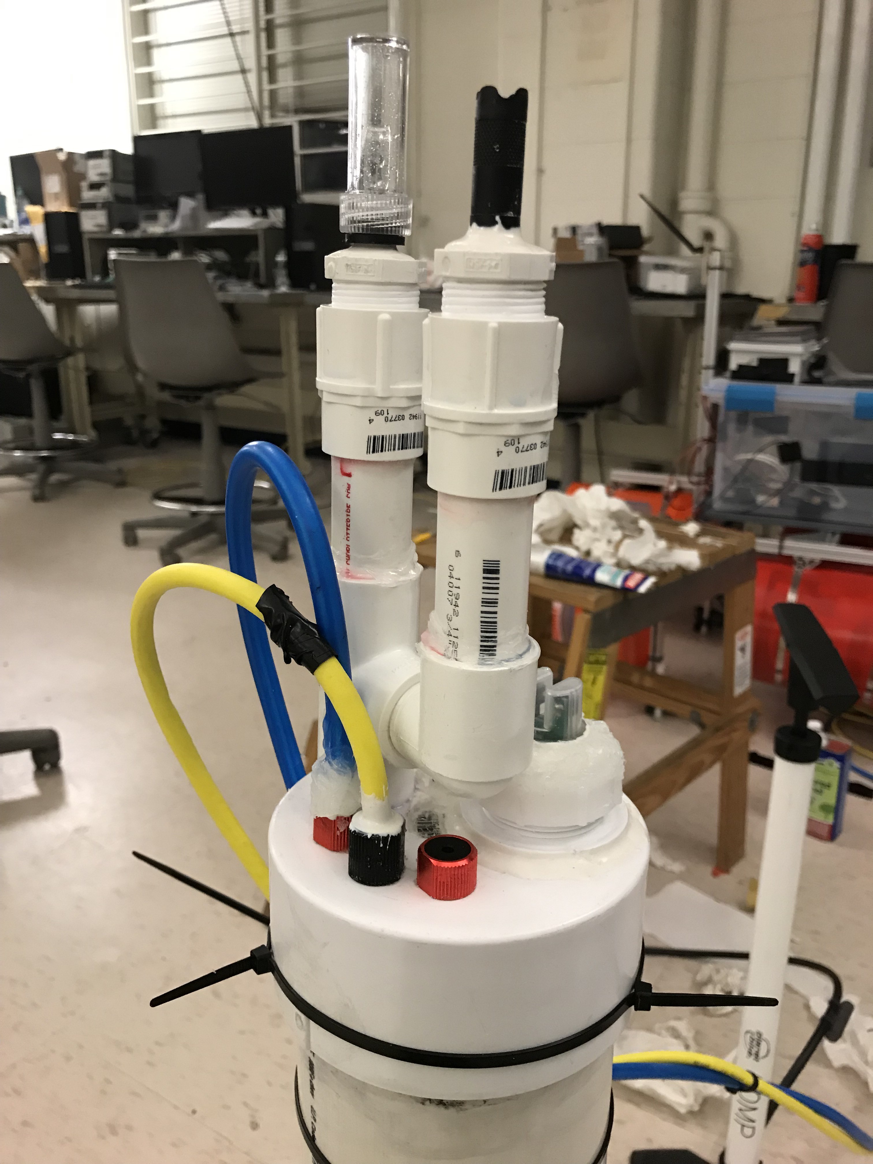
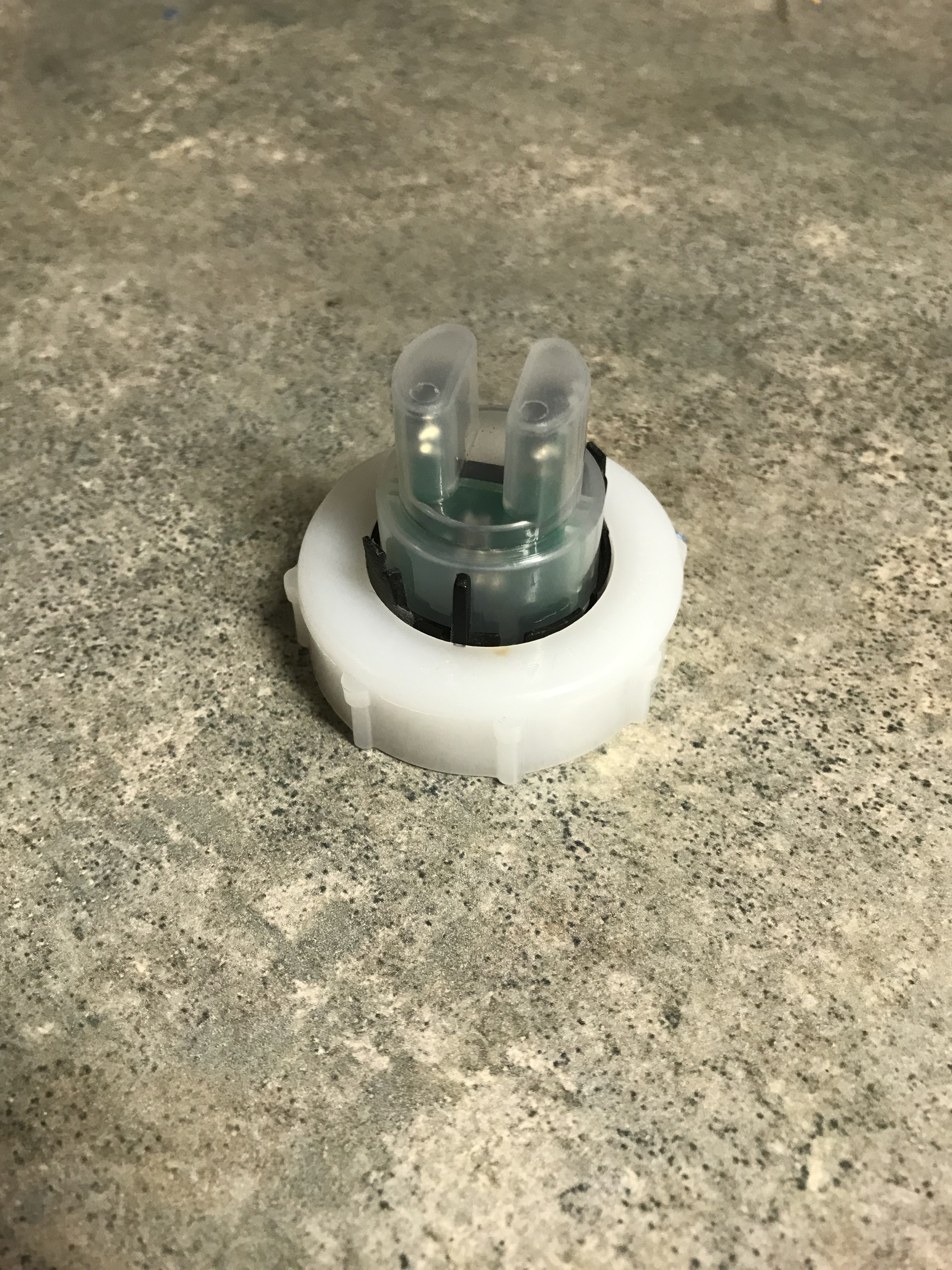
With that longer than intended sealant discussion out of the way, let's move onto the cooler parts of this design. One of our first steps of ingenuity was using threaded PVC caps to make our sensors modular. For most of our sensor sizes, regular old 3/4'' male threaded PVC plugs (https://www.homedepot.com/p/Charlotte-Pipe-3-4-in-PVC-Sch-40-Plug-PVC-02113-0800HD/203850342) worked perfectly. We simply drilled a hole in the wall of the plug that just allowed the particular sensor at hand to slip through it, and then we sealed the edge between the plug and the sensor with the hard Loctite epoxy. Done. By then using a 3/4'' female fitting attached to the AUV, the sensors could be screwed onto and off of the AUV for an easy waterproof seal. The male plugs were also covered with standard plumber's tape to ensure a waterproof seal. There were a few exceptions to this design as well, though. For one, the ROV tether used to attach the AUV to the ASV did not need any PVC fittings, as being a Blue Robotics product we simply bought the appropriate cable penetrator (https://www.bluerobotics.com/store/cables-connectors/penetrators/penetrator-10-25-a-8mm-r2/) to go with it and connected the cable penetrator directly to the AUV's back. The second tether we used also used a similar penetrator. Our pH sensor also didn't need a plug fitting, as it was already male-threaded on its handle and could screw directly into a female PVC fitting on the AUV. Our turbidity sensor was also too big and oddly shaped for the PVC plugs we found, so we ended up using a trap adapter to build this attachment instead (https://www.homedepot.com/p/NIBCO-1-1-2-in-PVC-DWV-Trap-Adapter-C480127HD112/100347086?MERCH=REC-_-PIPHorizontal2_rr-_-100345781-_-100347086-_-N). Finally, our depth/temperature sensor was also threaded and could be inserted directly into the AUV while still being modular. As the surface area of the AUV's back (a 4'' diameter circle resulting from the main body being a 4'' diameter PVC pipe) to attach each sensor directly to the back's surface, we created a breakout attachment for two sensors using some 3/4'' PVC pipe, a 90 degree PVC fitting, and a tee PVC fitting. Some images of these modular sensor housings are shown below.
![]()
Sensor fittings with pH sensor adapter (rightmost hole) visible
![]()
Overview of sensor fittings, with blue ROV tether, yellow ROV tether, depth/temperature sensor (red), turbidity sensor (back), conductivity sensor (top left), and dissolved oxygen sensor (top right)
![]()
Turbidity sensor being fitted to trap adapter housing
As seen in these images, the sensors all attached to a 4'' PVC cap placed on the end of the main 4'' pipe body of the AUV. Holes were drilled into this cap to attach the fittings. The cap was PVC sealed to the pipe, and the female attachments were also PVC and hard Loctite sealed to the cap. The back of the vehicle was thus not removable, and all inserting and removal of the inner electronics would occur through the front of the AUV. Therefore, the front of the AUV had to be designed to be both waterproof and removable. The conventional means of doing so would be by creating an O-ring attachment for the AUV nose. However, given our lack of experience in O-ring design, lack of machinery for creating the specific grooves needed by the O-rings, and lack of time, designing a custom O-ring attachment was not an option. Our solution, therefore, came from stumbling upon what's called a PVC test plug (found here https://www.homedepot.com/p/Oatey-4-in-Gripper-Mechanical-Plastic-Test-Plug-33403D/100204964). The plug was designed for 4'' PVC piping and is meant to seal off a pipe when repairs are being performed on it. The plug features an expandable O-ring that forms a watertight seal when screwed onto the end of the pipe. Therefore, we simply had to screw this plug into the PVC nose and we were set to have a watertight, removable front seal.
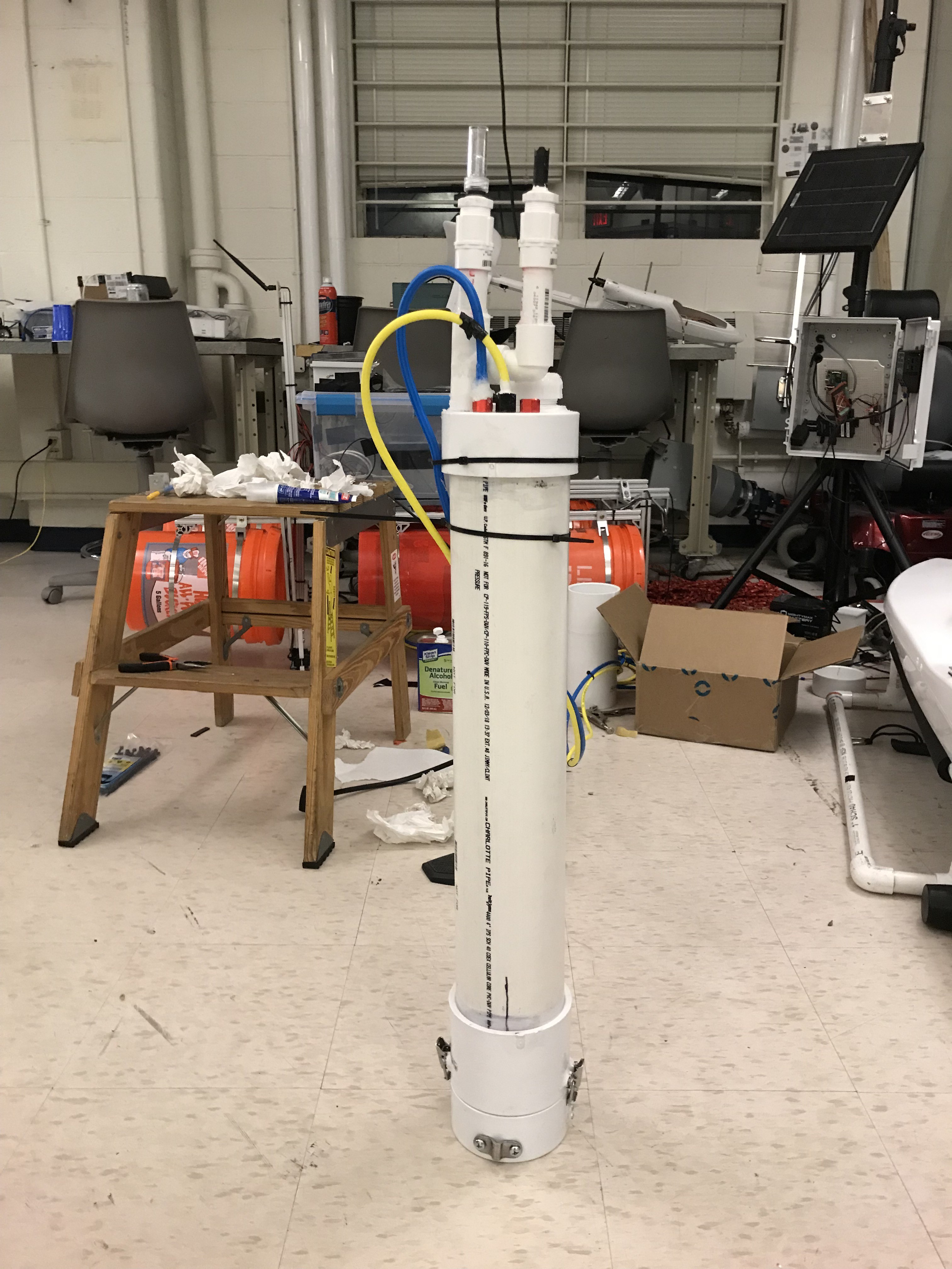
The next task was figuring out how to configure the water intake for the buoyancy system in such a way that it could be easily detached and reattached when the inner electronics/buoyancy system had to be inserted and removed. We opted to have a tube on the inner buoyancy system attach in a removable manner to an intake hole with a prong on the end. To make sure that the prong did not stick up too far and block the inner housing from being inserted, it was attached in the gap of a male-to-male 4'' PVC fitting. This fitting can be seen on the end of the AUV right before the nose. This also allowed the nose (a 4'' PVC cap) to sit flush on another surface, allowing us to install clamps on the nose and put a secondary O-ring in the groove between nose and male-to-male fitting for additional waterproofing. A guide was also installed on the nose cap for guiding the ROV tethers from the back of the AUV to its front and for securing the tethers firmly to the AUV. Thus, the front of the AUV was assembled in the order of main PVC body --> male-to-male fitting --> small 4'' PVC pipe piece --> 4'' test plug --> clamped on nose cap. An image of the almost finished AUV externals can be seen below.
![]()
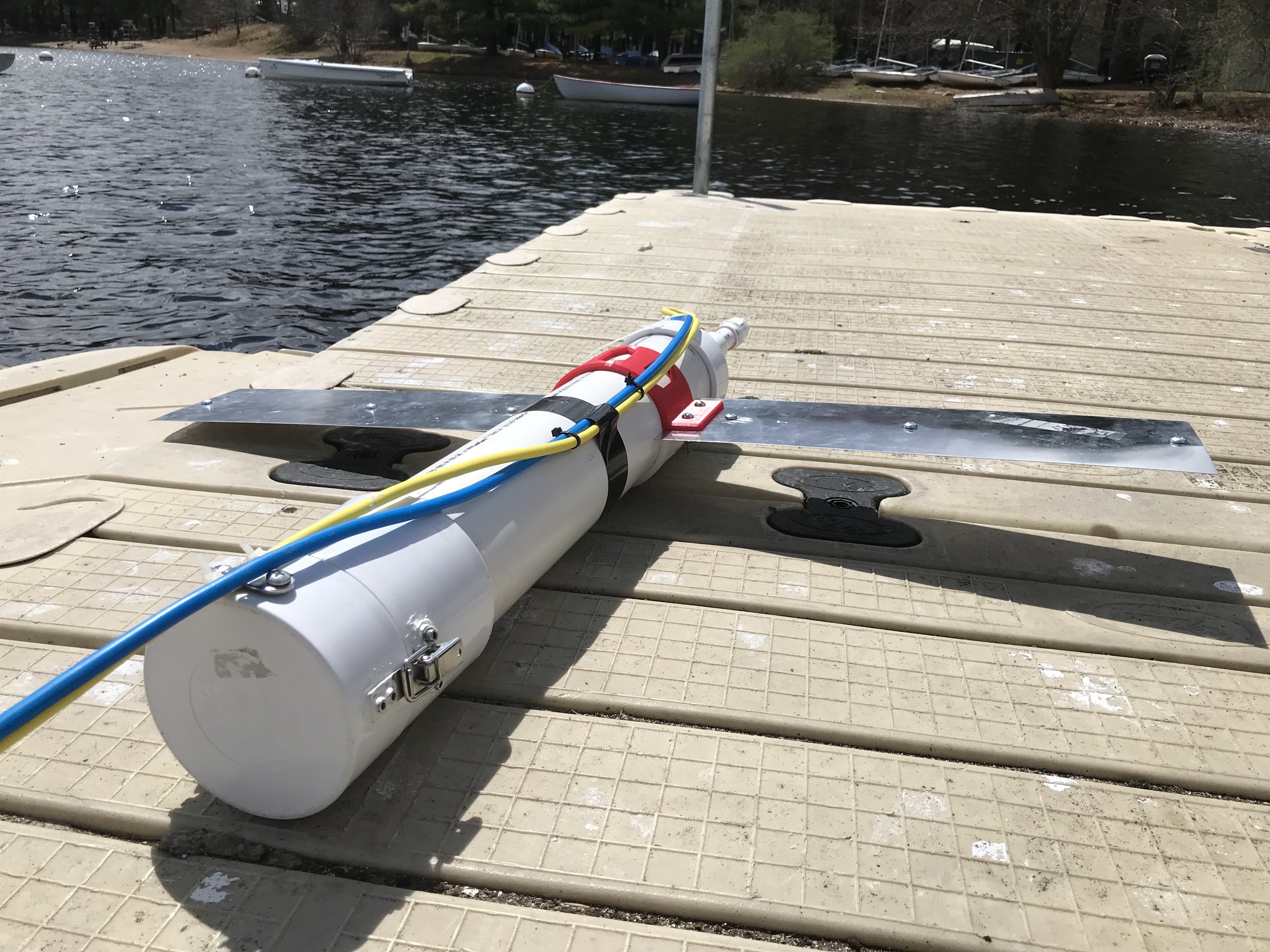
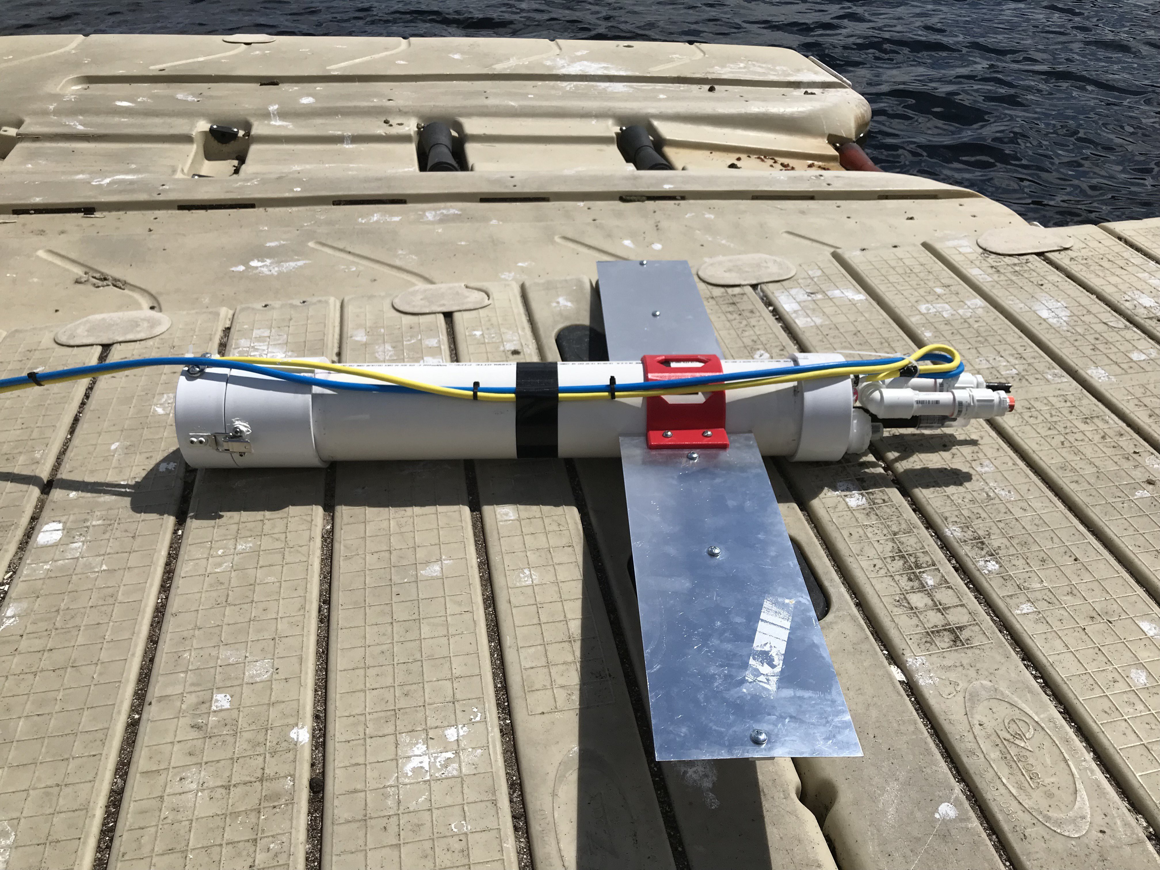
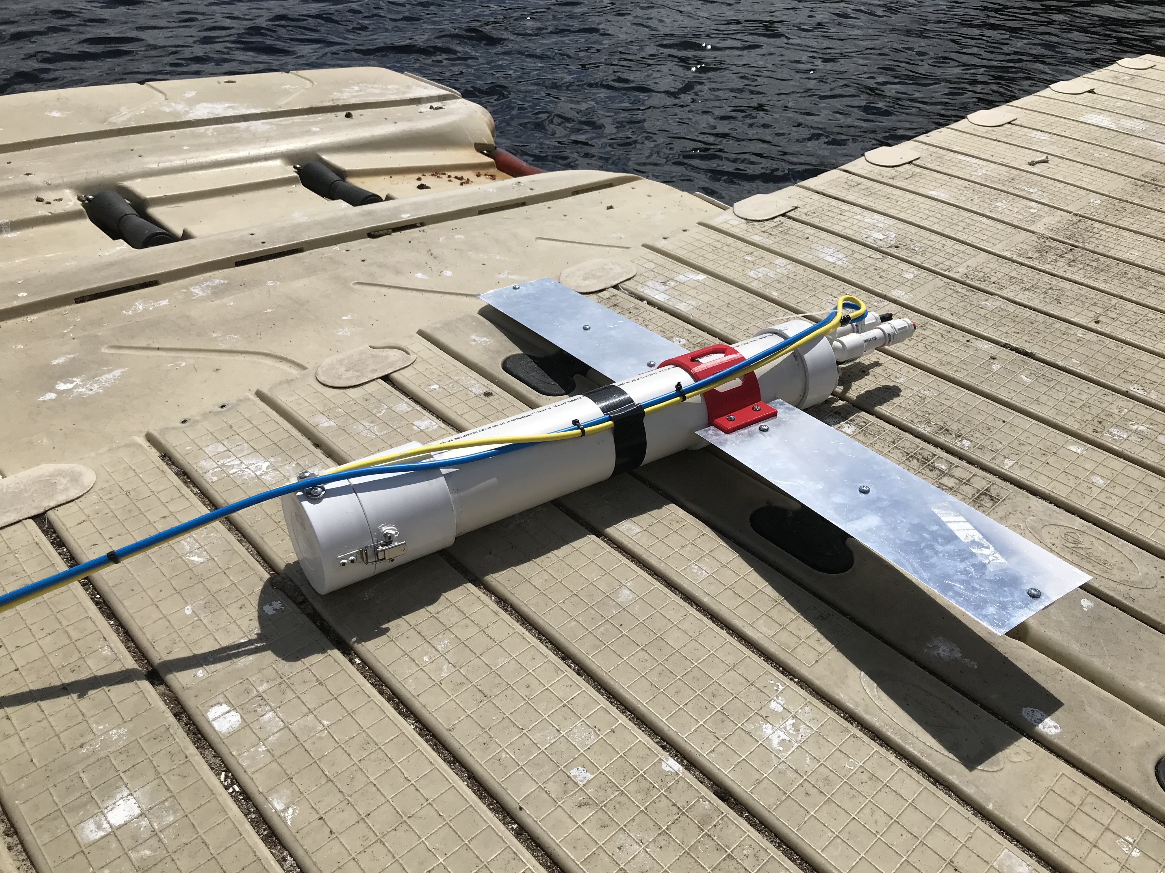
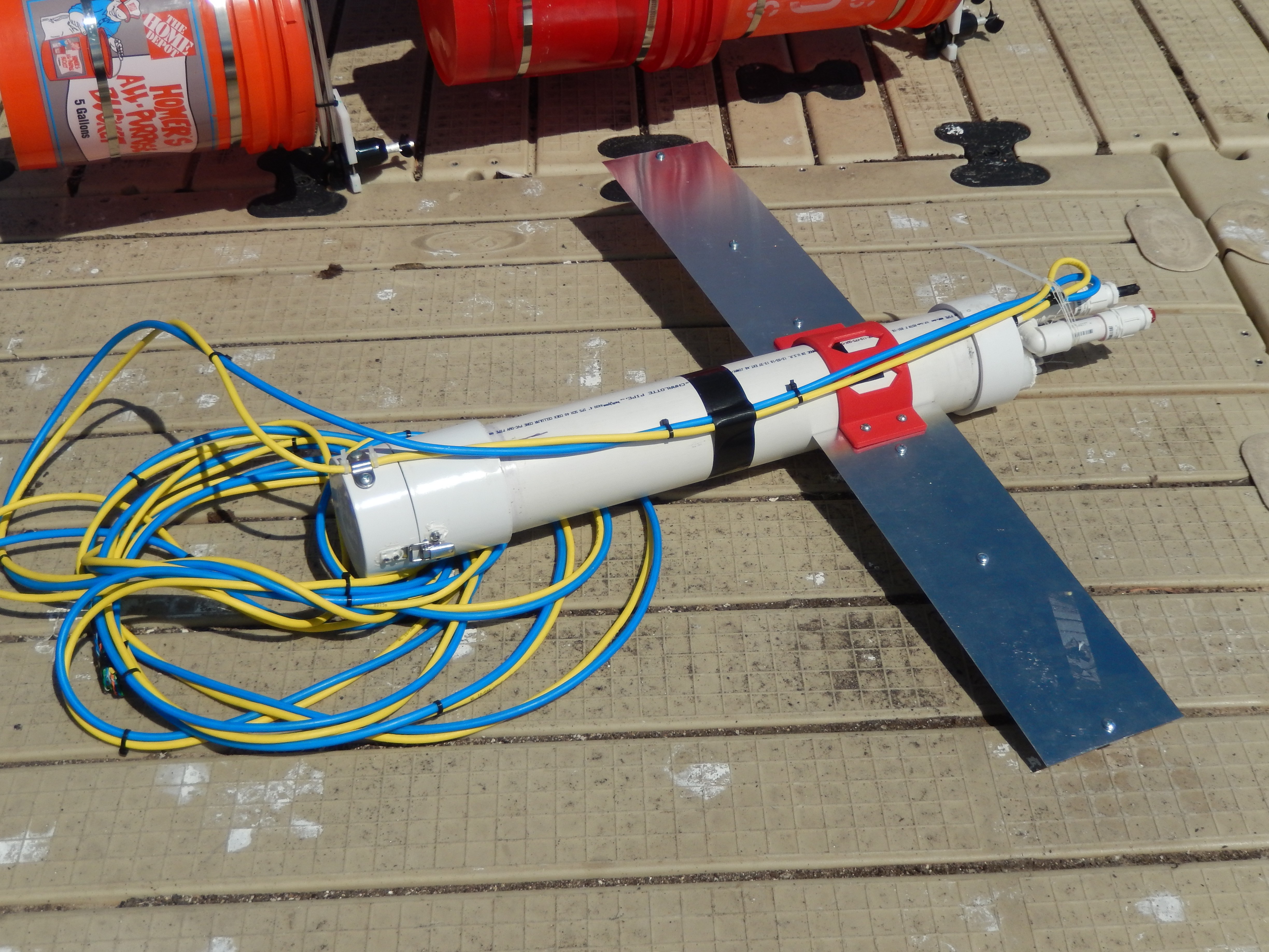
The final step in finishing the AUV externals was to build and attach the wings. The wings were meant to stabilize the vehicle and prevent it from any excessive rolling as it moved through the water. The wings themselves were made of two thin aluminum sheets purchased from Home Depot. Aluminum bars of 1/4'' thickness were screwed into the wing sheets to give them additional support. The wings were mounted to the AUV using two 3D printed wing mounts, based on the design from the open source underwater glider mentioned previously. The final AUV externals can be seen in the following images.
![]()
![]()
![]()
![]()
-
10Building the AUV - Internal
The internals of the AUV performed the heavy work of actually taking water quality measurements and controlling the submersible's buoyancy. Evidently, it also required a sophisticated mechanical design to fit the necessary components into the confined 4'' pipe main housing while still maximizing the vehicle's performance. We again used the OSUG: Open-Source Underwater Glider hackaday project (which can be found here https://hackaday.io/project/20458-osug-open-source-underwater-glider) to assist us in building this design, so thanks again to that project!
The first design parameter that had to be decided upon was picking out the syringes that would be used in the submersible for buoyancy control. We wanted to maximize the volume of water that we could pull into the syringes to correspondingly maximize the control over the AUV's buoyancy that we had. However, at the same time we wanted to minimize the space taken up by these syringes so that we could fit the entire internal system in a pipe of 2 feet in length. Obviously, these two goals conflicted with each other, so we had to settle on the perfect middle ground between the two.
After performing some calculations with the 4'' x 2' main PVC pipe housing dimensions and the dimensions of the different syringe options we found online, we decided on using three 150 mL syringes for buoyancy control (which can be found here https://www.amazon.com/gp/product/B07BJ9P8FP/ref=ppx_od_dt_b_asin_title_s00?ie=UTF8&psc=1). These three syringes were just barely capable of fitting side by side into a custom mount that could fit inside the 4'' pipe. Additionally, the total volume of water capable of being captured by these syringes (450 mL) was greater than the volume produced by any other combination of syringes of other sizes that could still fit in the 4'' pipe. Thus, this syringe combination effectively maximized our potential for intaking water for buoyancy control out of all of the syringe options we saw in our search. Assuming a water density of 1000 kg/m^3 (1 g/mL) for simplicity, this volume of 450 mL would allow us to change the effective buoyancy of the AUV by 450 g, or about 0.992 lbs. In this manner, by calibrating the weight of the AUV to be approximately neutrally buoyant with no water in the syringes, the hope was that by intaking water and changing the effective weight of displaced water (water displaced by the AUV) by about a pound, the AUV would begin to sink at a steady rate even with the forward motion force of the ASV. We performed some empirical testing with the system, and found that we could calibrate the AUV's weight to be close enough to neutrally buoyant (while erring on the positively buoyant side so that the AUV would naturally float with no water in the syringes) that intaking just 115 mL of water into the syringe system would cause the AUV to begin to sink. Intaking the full 450 mL of course made the AUV sink faster. Thus, we proved empirically that our buoyancy system could feasibly allow the AUV to alternate between being positively buoyant and negatively buoyant. When the syringe plungers were fully extended, the syringes measured about 16 inches in length. This would leave about 8 inches of room in the 2' length pipe to fit the component mounts, the stepper motor, the two Arduino Unos, and the sensor interface boards. While this wasn't much space, we developed a design that feasibly squeezed everything in.
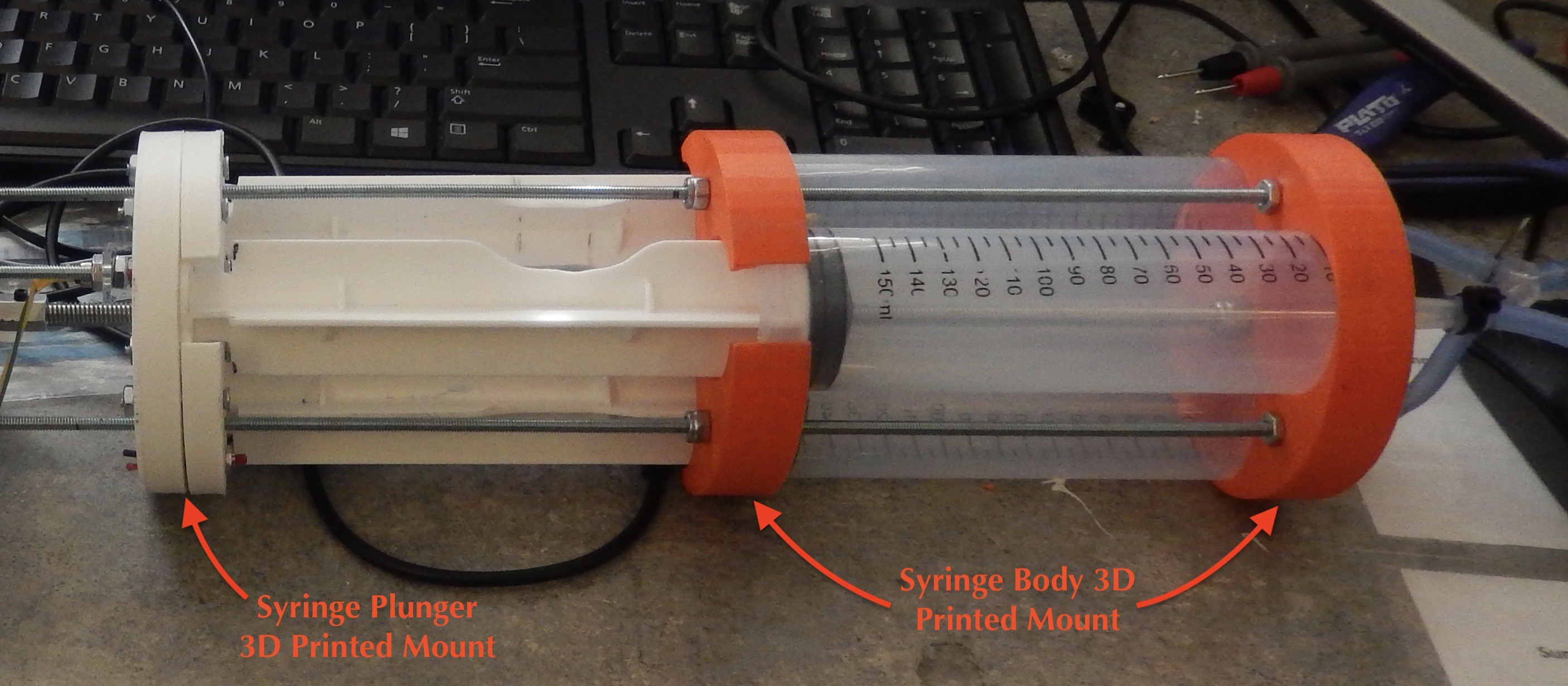
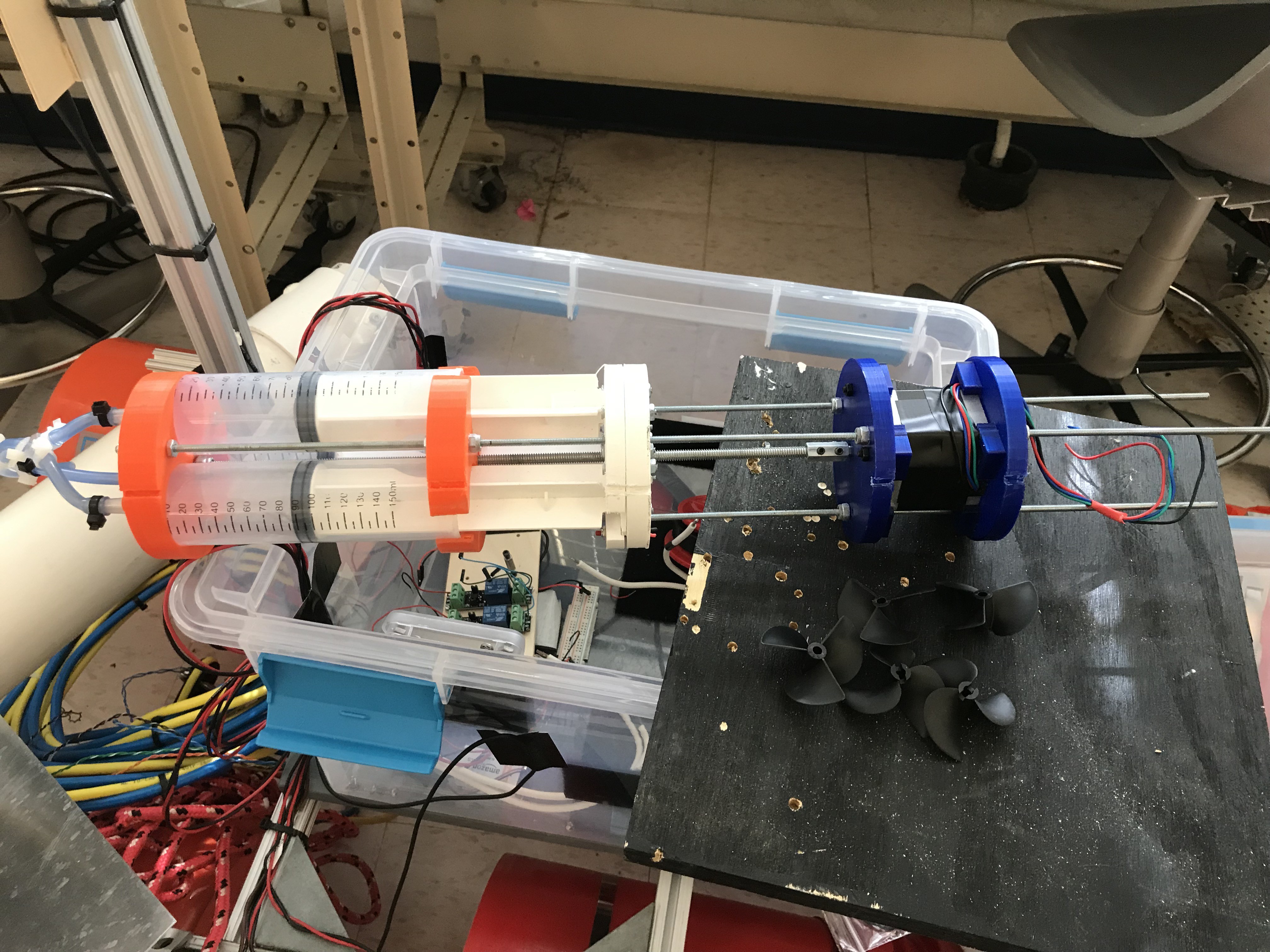
The system for controlling the positioning of the syringe plungers (controlling the intake/expelling of water into/from the syringes) functioned as follows. Two 3D printed mounts would attach to the fronts and backs of the syringe bodies to hold them firmly in place. An additional 3D printed mount would attach firmly to the backs of the syringe plungers. Thus, holding the first 3D mounted prints in place and pulling on the second 3D mounted print would allow the syringe plungers to be pulled out. This syringe body and syringe plunger 3D printed mount system is showed in the image below.
![]()
The syringe plunger 3D printed mount contained a standard nut (1/4 in.-20) secured in its center and constrained so that it could not move independently of the mount. A 1/4 in.-20 threaded rod was then threaded through this nut and all the way through holes in both ends of the syringe body mount. Two lock nuts were threaded onto the rod on both faces of the end syringe body mount piece. This restricted the rod from having any linear motion. Thus, when the rod was turned, the nut in the syringe plunger mount would thread up or down the rod, thus moving the syringe plungers in or out. In this manner, a motor could be used to spin the 1/4 in.-20 threaded rod and control the positioning of the syringe plungers to intake or expel water. Three thinner #8-32 threaded through rods were used to secure the non-moving mounts together.
A stepper motor was chosen to control the motion of the 1/4 in.-20 center threaded rod as this type of motor would be easiest to interface with while providing great power and range of motion. To attach the stepper motor shaft to the center threaded rod, a 1/4 in.-20 coupling nut was used (https://www.truevalue.com/shop/hardware/fasteners/bolts-nuts/nuts/steel-coupling-nut-coarse-thread-1-4-in-20). Two holes were drilled into the coupling nut for set screws, and the end of the center threaded rod was filed to create a flat face. From here, the coupling nut could be threaded onto the end of the center threaded rod, slipped onto the stepper motor shaft (which was also 1/4 in.), and secured by having two set screws screwed into it (such that the set screws then sat on the flat faces of the threaded rod and the motor shaft). With the coupling nut secured, any motion made by the motor shaft was directly transferred to the center threaded rod with no slipping and very little wasted friction.
The stepper motor we chose for the AUV was a Nema 23 stepper motor (which can be found here https://www.amazon.com/gp/product/B00PNEPF5I/ref=ppx_od_dt_b_asin_title_s00?ie=UTF8&psc=1). The stepper motor had a current limit of 2.8A and a maximum torque output of 178.5oz.in/1.26Nm. We chose this motor based on its size, price, and some back of the envelope torque calculations that a mechanical engineering friend of ours made for us. We predicted that this motor would have plenty of torque to move the plungers effectively, even with the increased pressure force on the intake hole at larger water depths (we wanted the AUV to be capable of reaching a maximum depth of about 30 feet). In reality, some empirical torque experiments we performed with the system proved that it would only be capable of overcoming the water pressure (pushing water out despite the inward pressure force of the water depth) at pressures up to about 6 psi, which occurs at a water depth of about 14 feet. However, as we did not have time to redesign the system after conducting these empirical experiments, we continued forward with this stepper motor and just limited our testing depth more. In the future, we would figure out how to use this motor's torque output more effectively or use a different motor to make the AUV able to travel deeper.
We used the AMIS-30543 stepper motor driver (which can be found here https://www.amazon.com/gp/product/B01MCUTE46/ref=ppx_od_dt_b_asin_title_s01?ie=UTF8&psc=1) to drive the stepper motor, as it provided an appropriate current output to match the requirements of the Nema 23 motor and contained a well-maintained open source library of example code.
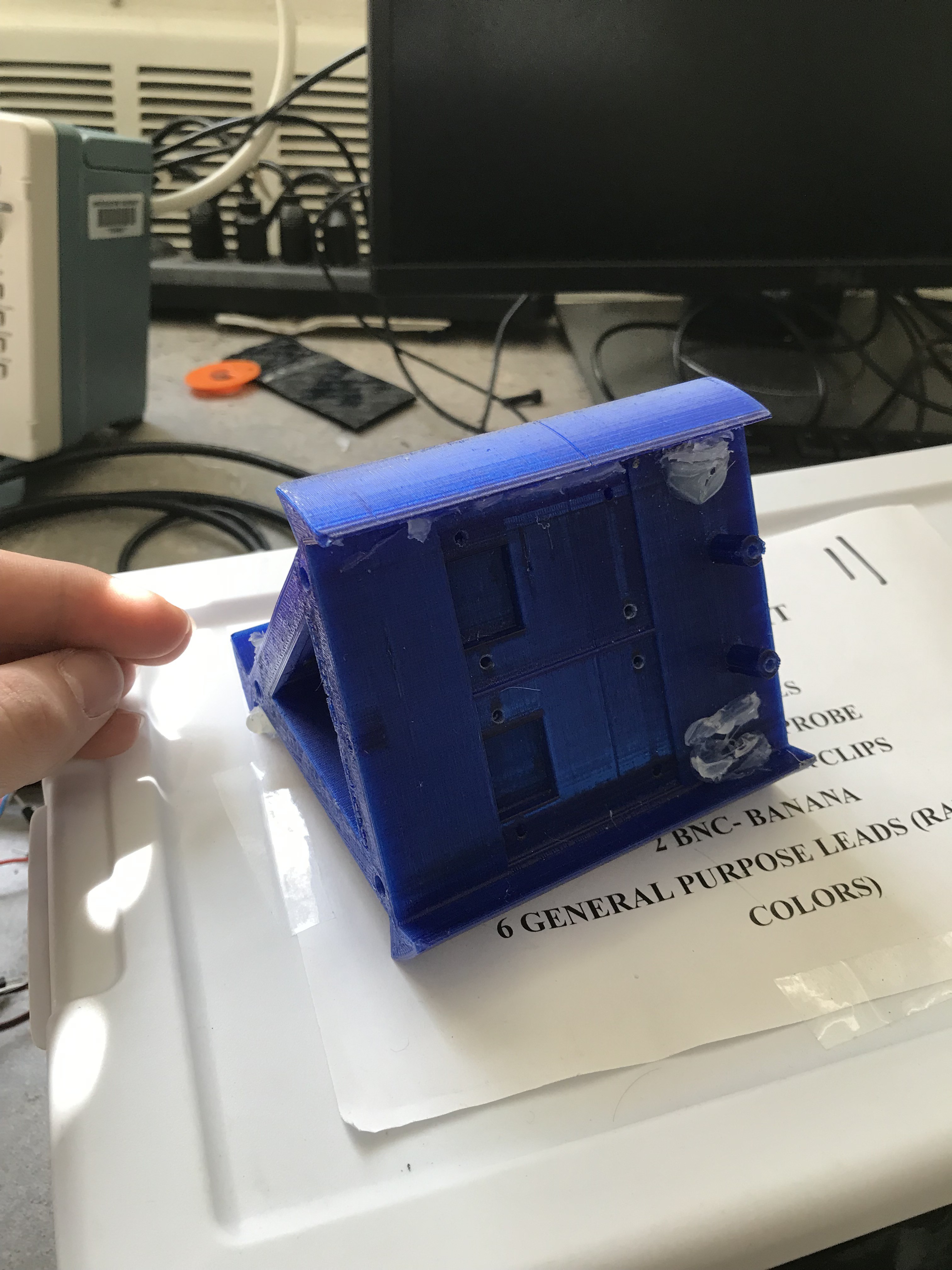
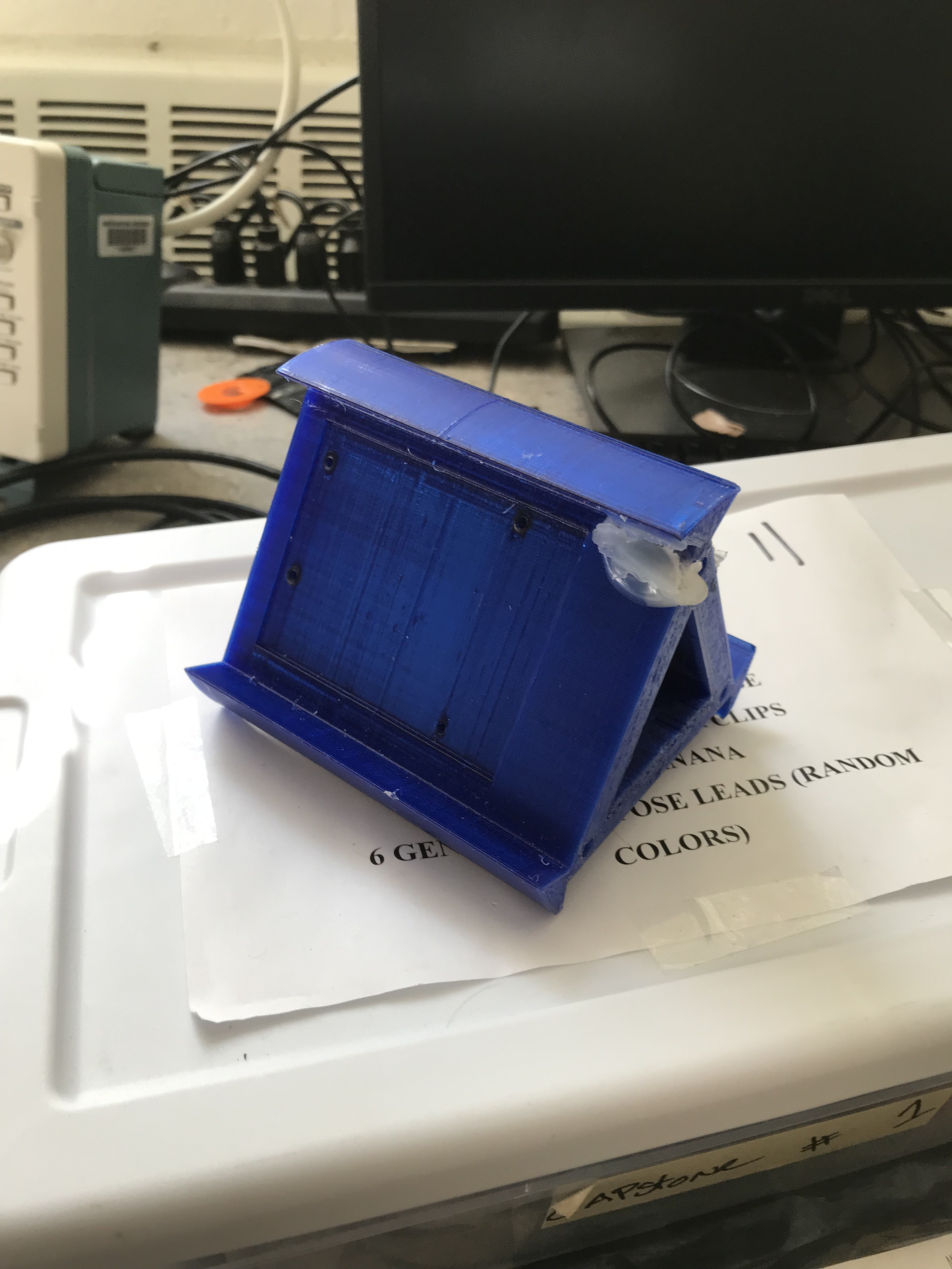
A 3D printed mount was developed to hold the stepper motor in place. Additionally, an interesting 3D mount was developed to hold the two Arudinos, the motor driver, and the four sensor interface boards. This mount took the form of a triangular prism with a hollow center and rounded edges (to sit flush on the round pipe surface). Two of the prism faces were used for mounting the two Arduinos, while the other face was used for mounting three of the sensor interface boards (the conductivity, dissolved oxygen, and pH sensor boards). The motor driver and the last sensor interface board (the turbidity board) were mounted on one of the inside faces. This mount allowed us to place a large number of components efficiently in a very small space (the mount was only 4 inches in length), and can be seen below...
![]()
![]()
Latex tubing was used at the front of the syringe system to connect the three syringe tips to one central tube that could be connected to the intake hole in the main PVC pipe housing. Additionally, two push buttons were installed to serve as end stops for the syringe plunger mount. One push button was installed on the stepper motor housing facing the plunger mount, and the other was installing in the plunger mount itself facing the syringe body mount. These end stops would be used in emergency situations if the stepper motor accidentally tried to pull/push the plungers past their defined range of motion in either direction. If an end stop button was pushed, the Arduino controlling the stepper motor would stop whatever motion was occurring and understand where the plungers were based on which push button was pressed. The end stops could also be used to calibrate the plunger positioning on startup. By moving the plungers all the way forward until the front push button was pressed on startup, the buoyancy control Arduino would be able to know where the plungers were always on startup and then calculate further plunger positions based on the known movements from this point.
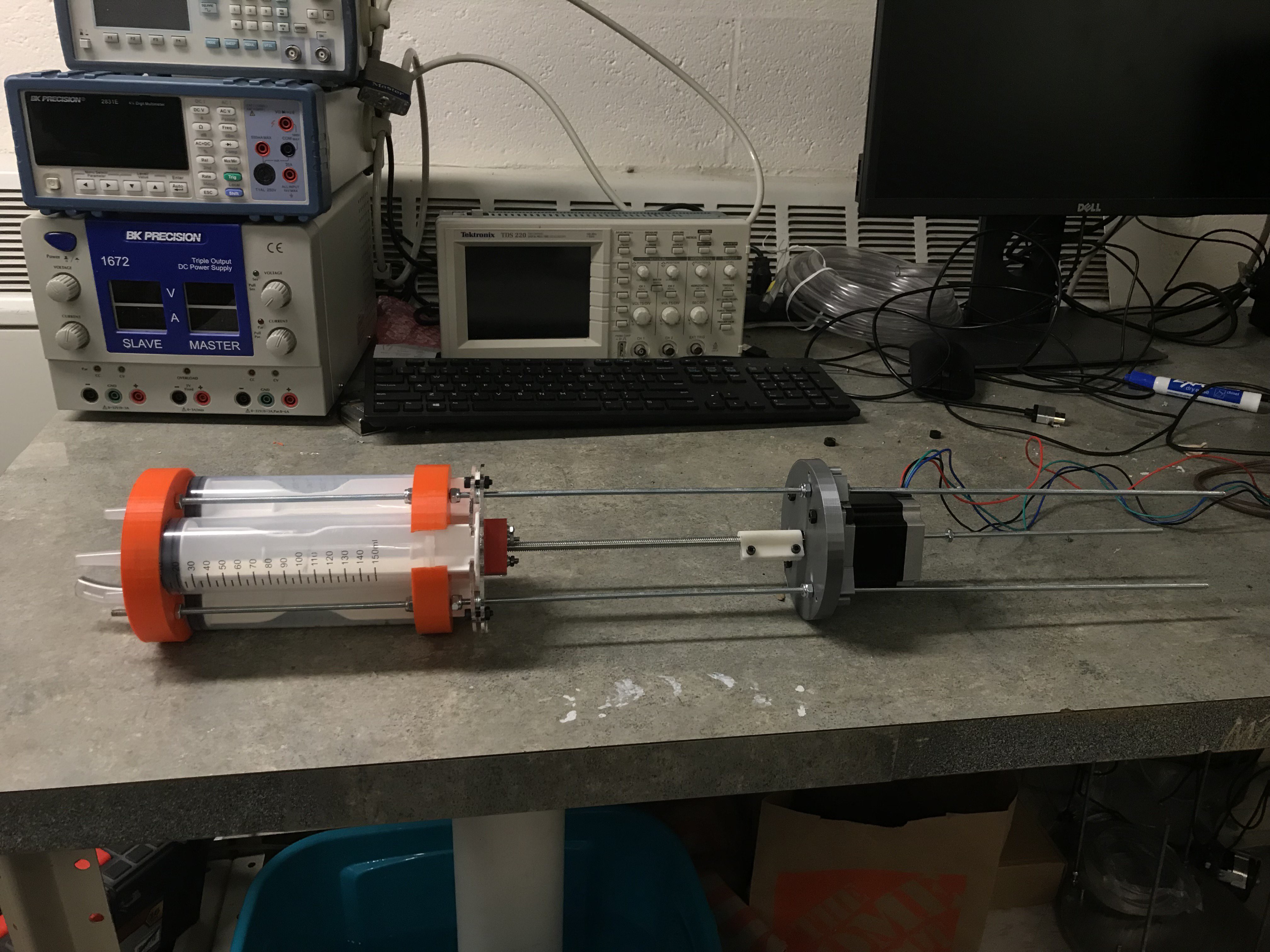
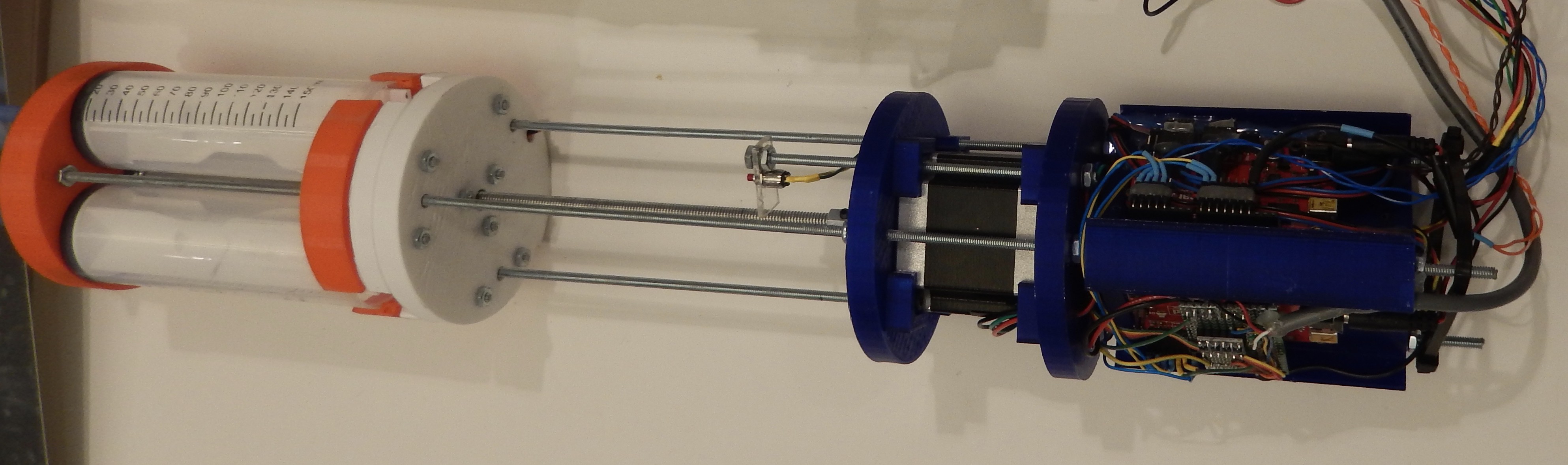
With these designs implemented, the AUV internals were complete. Attached below are some additional images of the internal AUV system.
![]()
One of our initial prototypes of the AUV internal system
![]()
![]()
Project Albatross
Subsurface Data Acquisition using Semi-Autonomous Aquatic Robotics
Discussions
Become a Hackaday.io Member
Create an account to leave a comment. Already have an account? Log In.
Fantastic build, well and satisfyingly documented. Congratulations!
"This power would be a 24 V signal capable of drawing up to 3 A, potentially. However, based on our experience and on some online research, the 26 AWG wire in the Blue Robotics tether could carry a maximum current of 1 A safely."
A boost converter on the surface and buck converter underwater might be a candidate for this solution. Cooling might have been a problem, but perhaps some other constraint might have ruled this solution out?
"To make the plot generation real-time while not wasting resources,..."
A resource that is not used is wasted. What was the limiting resource?
Are you sure? yes | no