Evan
Evan-
PCB prototype testing
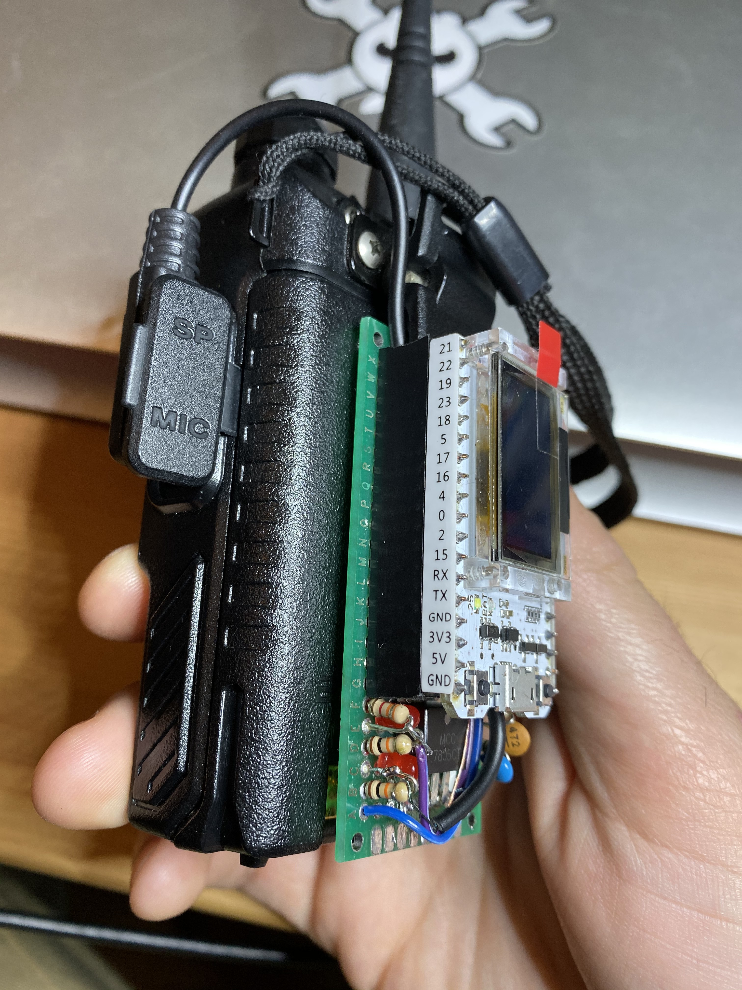
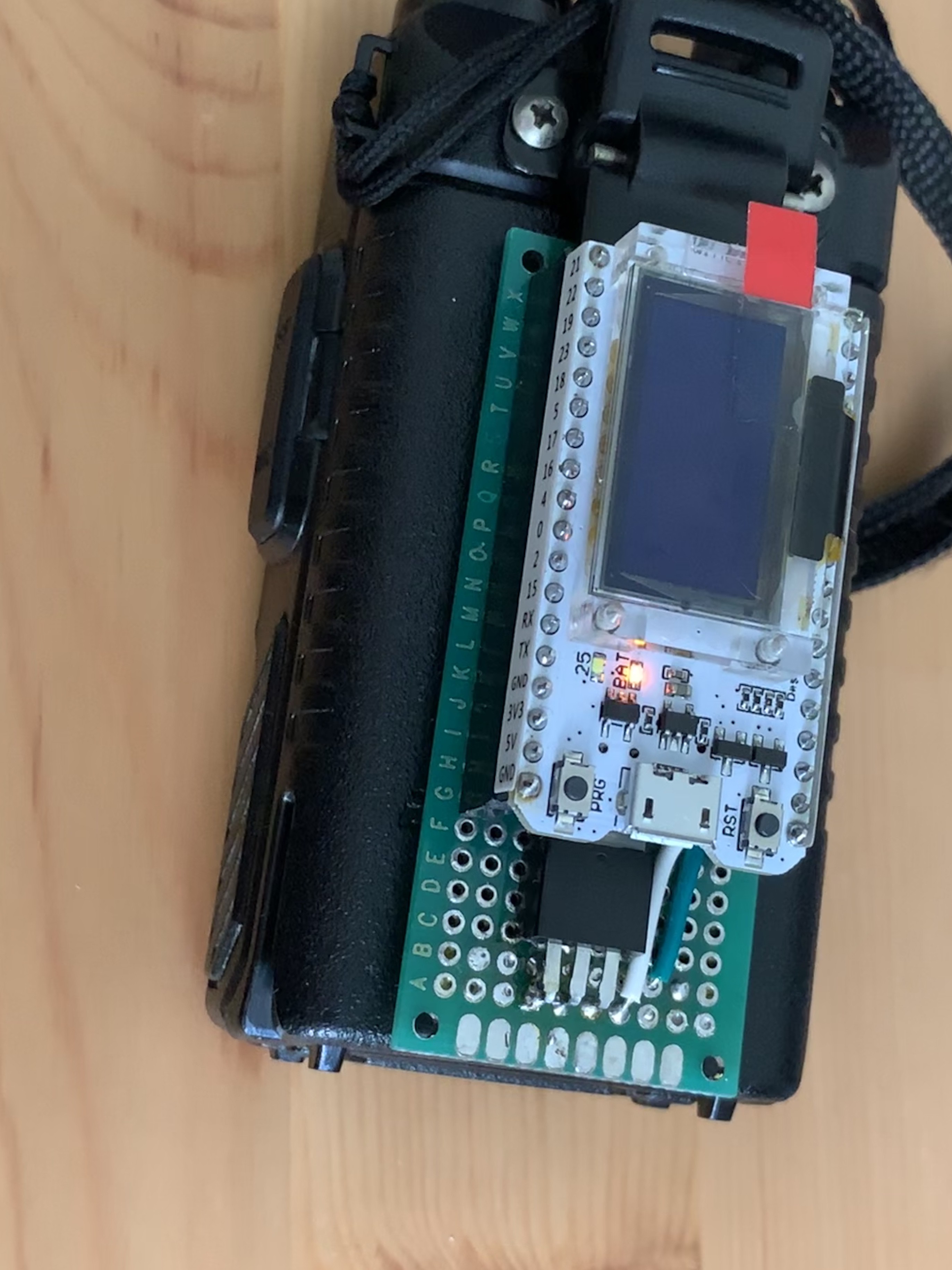
10/20/2020 at 03:45 • 1 commentMy PCB prototypes arrived today, and I went straight to test them. They generally seem to work!
A day or two after I ordered the PCBs, I noticed that I had used a 6.3V-tolerant capacitor across Vbat and ground. Since the Baofeng uses a 2-cell lithium ion battery, max battery voltage is around 8.4V. Whoops. So, before testing, I desoldered this capacitor.
I did some basic continuity tests, checked the polarity of the diodes, and then applied 5V across the 5V/GND pins on the programming header and checked Vcc. This read 3.57V -- higher than the 3.3V spec, but within the absolute maximum rating of the ESP32. (Once I soldered the ESP32 on, which provided a load for the power supply, this dropped to 3.31V -- much better.)
I did some voltage checks on the programming header to make sure I wasn't going to blow up my wESP32-Prog, then plugged in the programmer and flashed the ESP-IDF Hello World app. This worked, though I had to keep constant torque on the pins to get good contact. The wESP32 has staggered pins for its programming header, which gives a friction fit for the wESP32-Prog. I had meant to do this, but didn't get around to it before ordering.
Things to change for revision 2:
- The slot where the clip is supposed to nestle needs to be a tiny bit wider -- I'm not getting much engagement on it.
- The slot for the clip also needs to be moved -- it's too far from the top of the board, so once the ESP32 is soldered on, the clip doesn't reach it. This will probably mean moving the programming header to the other side of the slot. This ought to be more convenient anyway, as it would allow the board to be programmed while attached to the back of the radio.
- Remove or change the part number for the Vbat bypass capacitor to something that can tolerate 8.4V
- Possibly replace the entire power supply with a circuit that has lower quiescent current.
- Stagger the programming header pins, to allow wESP32-prog to friction fit.
- Labels on the PCB for the different headers. At the moment I need to reference the schematic and this handy page to figure out which headset wire needs to go to which pin.
- Some sort of strain relief for the headset cable -- possibly just a pair of ~2mm holes to weave it through.
-
PCB prototypes ordered
10/10/2020 at 06:33 • 0 commentsWhile procrastinating on solving the software issues around the ADC, I've been working on a PCB layout. I finally finished the layout tonight, and ordered some PCBs from JLCPCB.
Here's hoping it all works!
The board has:
- Breakout of most of the ESP32-WROVER module's pins
- A cutout where the Baofeng's belt clip can sit and keep the board in place.
- A header meant to interface with the wESP32-Prog module (to help minimize the number of components)
- A DC-DC power supply based around the XL1509 (the cheapest non-inverting DC-DC converter IC available as a "basic part" from JLCPCB).
- The audio components
- a clamp circuit that lets us get an interrupt when the audio input goes high without blowing out the GPIO pin.
- a 4:1 voltage divider to drop the Baofeng's 0-8.4V audio output down to a range tolerable by the ESP32's ADC
- A voltage divider / RC filter / DC blocking capacitor for smoothing the DAC output and dropping it to a level that the Baofeng's microphone input can handle.
The clamp circuit on the PCB is different than what I've prototyped (it uses a 3-terminal voltage reference instead of 2 red LEDs), and my prototypes have been using DC-DC modules from aliexpress, so if I made a mistake it's likely in one of those two places.
For the DC-DC converter, I was going to use the same IC as these aliexpress modules, the MP2315, but that's an "extended component", and I balked at paying an extra $3. That may have been a mistake in hindsight -- the XL1509 has higher quiescent current and lower efficiency than the MP2315, which may end up negating the benefits of using a DC-DC converter instead of a simpler linear voltage regulator. I only noticed this after placing my order.
Assuming this works & doesn't require too many more components, I'm pretty happy with the result. In small quantities (5pcs), these boards cost $8 each for manufacture/assembly/shipping. JLCPCB doesn't stock any ESP32 modules or do through-hole assembly, so 0.1" header pins + the ESP32 module + the pogo pins I'm using as battery contacts still need to be added, which should be less than $5 per board.
This is my first PCB layout, so I'd love to hear any feedback you have on the design.
-
PTT working, final prototype assembly, and some bug fixes
09/30/2019 at 05:30 • 0 commentsToday I finally permanently soldered my headset connector into my board, which means I can actually pick up the project and carry it in one piece.
![]()
Since I’m cannibalizing an off the shelf headset for the Baofeng, the wires inside my cable were super tiny and had enameled insulation. For now I’m using the fire method for stripping these but it’s not ideal: the insulation lights on fire and flames travel along the wire. Apparently fine grit sandpaper or some scary chemicals work pretty well. I think I’ll try sandpaper next time.
Barring any issues that come up, I think this means I won’t have to make hardware changes for a while. I’d like to make a PCB for this instead of perfboard, and probably use an ESP32 castellated module instead of a breakout board, but in the meantime I think I’ll work mostly on software.
On the software side, I coded up a PTT pin (up until now I had just been holding the PTT button when I wanted to transmit 😅), and fixed a bug with the formatting of my APRS locations, so now they are actually being parsed correctly by aprs.fi. -
A simple webapp that uses phone's GPS and sends location via APRS
09/26/2019 at 17:20 • 1 commentIn my most recent commit, I added a simple webserver that has two endpoints:
- Some static HTML+javascript served from /
- A POST target that takes latitude+longitude and sends them out via an APRS packet
The code ended up being fairly straightforward. It's certainly not amazing UX right now -- I really should add a button or something on the HTML page to trigger geolocation sending, as right now it just sends location when you load the page.
Ultimately I think it would be nice make an APRS web interface that would allow you to both send your current location and see the received location of others. (I would have the esp32 store these locations whenever it hears an APRS packet).
In iOS13, it looks like webapps saved to the home screen have the ability to execute code in the background, which is exciting: if we can access geolocation and XHR apis while backgrounded, we could periodically broadcast our location via APRS.
Unfortunately, there's still no way for a webapp (even one installed to the homes screen) to create push notifications on iOS. This means I still can't use a webapp for the PBBS functionality I want to add, where users would receive some sort of push notification when we detect a message for them, at least on iOS. I think the Android PWA ecosystem is much more full-featured.
-
AX25 transmission works
09/18/2019 at 06:54 • 0 commentsI finally managed to get my hacked up version of LibAPRS for ESP32 transmitting properly. I've had it almost working for several weeks, but couldn't get the audio output to be smooth -- it would occasionally jump suddenly between values. (The AFSK modulation used in AX.25 is supposed to be continuous-phase, and LibAPRS produces correct values, so this was a problem in my code.) I think I was underflowing my I2S buffers or something. By tweaking buffer sizes (both audio and AFSK bytes), it finally seems to be somewhat reliable. Good thing the ESP32 has a lot more memory than an ATMEGA328P.
It's still not 100% reliable, even when going straight from audio output to my KPC-3+. Seems to decode properly about 50% of the time. But I was able to transmit at least one packet to an APRS IGate!
-
Successfully decoding packets
07/26/2019 at 21:58 • 0 commentsVia a dirty patch to LibAPRS that removes or emulates all Arduino-specific APIs, I was able to get packets decoding correctly.
The adc1_get_raw is the most straightforward way to sample from the ADC, but is not ideal:
- A task that repeatedly spins on the CPU until another 1/9600th of a second has passed (the way many Arduino sketches work) would monopolize the CPU too much to work well in the concurrent FreeRTOS environment on the ESP32.
- 9600 timer interrupts per second would be a lot of interrupts, and unless we dedicate one of the ESP32's two CPUs to the sampling task we would not be guaranteed access to the CPU in time
- Reading from the ADC this way takes ~1/6000th of a second.
The datasheet mentions that the ADC can run at 200ksps when controlled by the RTC controller (I'm not sure what the DIG controller is). What gives?
Well, it turns out you can instruct the i2s peripheral to sample from the internal ADC, and write samples into a buffer using DMA.
In my patched LibAPRS, I disable the interrupt code that executes every 9600th of a second, and then in my application I call AFSK_adc_isr repeatedly, once we have a buffer full of audio.
This works well, though it does mean I don't process packets until my radio's squelch closes. I think I may be able to refactor this to process smaller buffers as they come in.
-
Powering the ESP32 from the UV-5R’s battery
06/29/2019 at 23:32 • 0 commentsMy original plan was to power the ESP32 from the +V pin on the headset connector. However, I quickly discovered that the +V pin has 10kOhm resistance— certainly not capable of providing the 250mA+ needed by the ESP32 while using WiFi.
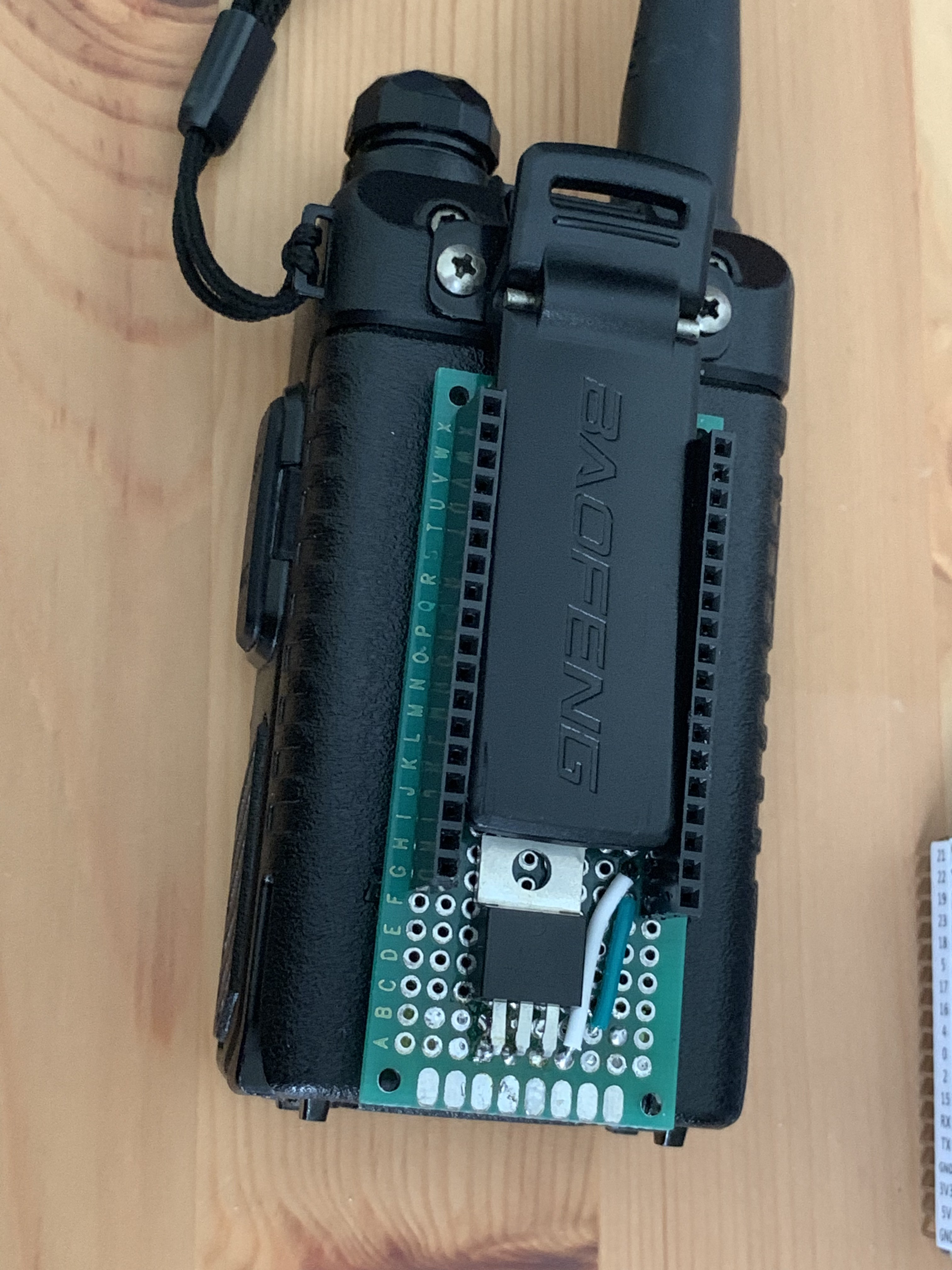
Plan B is to use the UV-5R’s battery’s charging contacts on the back:
![]()
This little backpack board is using two spring-loaded test pins, plus a 7805. (From what I’ve heard, the onboard regulator may be able to handle more than 5V input, but I’d rather play it safe. Going from 5V to the 8.4V of a freshly charged lithium ion battery would triple the voltage drop and power dissipation requirements of the regulator.)
It’s held in place with the spring-loaded clip on the back of the Baofeng, which happens to be just the right width to fit between the two rows of headers that mate with my ESP32 dev board.
![]()
-
Playing with Bluetooth PAN
06/13/2019 at 17:55 • 1 commentI learned that the ESP32 requires something like 90mA to maintain a wifi connection. This would limit the battery life -- the UV-5R's stock battery is 1800mAH. If using a linear regulator, the ESP32 in this mode would drain the battery in 20 hours on its own. With the HT's load, we probably couldn't expect more than about 12 hours of battery -- not super great in an emergency! (DC-DC converters could improve this, but would add to the BOM cost.)
However, I think we can do better. We only really need a network connection to the phone when there's data to send either direction. Can we shut down the connection until we receive audio from the HT (for receiving), or the user presses a button or something (for sending)? I'm not sure this is really possible with wifi -- if a phone isn't awake, I don't know if it bothers to look for wifi networks. (I still need to test this.) However, I think a bluetooth device can initiate a connection to a phone with which it has already paired.
Since I'm trying to avoid the need for any custom apps, I'm pretty much limited to TCP/IP. For Bluetooth, this means the PAN profile.
It doesn't seem like ESP-IDF supports PAN, but this github issue pointed me to BTStack, an alternate bluetooth stack that can run on the esp32, and has a PAN demo in its examples folder. Unfortunately, this demo is not supported on the esp32 -- it wants a POSIX system so it can dump packets into a TAP interface. However, reading the code a bit, I realized that if I implemented the functions exported in btstack_network.h, I could maybe get this to work. That was my goal with this repository, which tries to bridge btstack and lwip (the TCP/IP stack on esp32), and runs a DHCP server and a demo HTTP server.
After running into a few crashes and learning how to use core dumps and the gdb stub, I was able to get it to run without crashing when someone tries to pair with it, but it does not function properly yet. My laptop doesn't get an IP address assigned by the dhcp server, and cannot talk to the HTTP server. I suspect I'm doing something silly - maybe I need to unwrap the received packets a bit before forwarding them to LWIP.
After sharing my progress on the github issue, the maintainer of BTStack showed up with a new example that should do more or less the same thing, but hopefully work better than mine.
ESP32 AX.25/APRS TNC
A minimal-parts AX.25 / APRS TNC that can pair with a phone.