Kevin Kessler
-
Power Supply Board
09/23/2020 at 23:07 • 0 commentsMy initial design based on a TI TPS63000 buck/boost converter (for the 3.3V supply) and a Microchip MIC2288 boost converter (for 5V), turned out not to work very well once I got the PCB assembled. The MIC2288 drew several mA even when disabled so that wasn't battery friendly, and the I could not get TPS63000 to be stable.
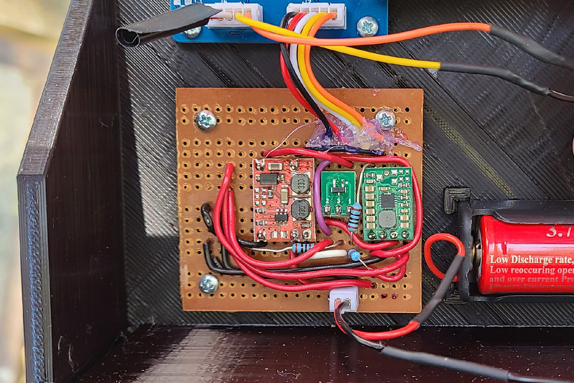
I did find a 5V boost converter in my parts drawer which had very low current when disabled (the red PCB), so I soldered that and a Pololu S7V8F3 3.3V Buck/Boost Converter(the PCB with all the caps on the right) to a piece of Perf board to get my Mailbox sensor out the door. This combination has a quiescent current of about 50uA.
The 5V power supply is only used to power the IR LED for the proximity sensor, so it is normally disabled and a GPIO pin from the uC enables the boost converter when it needs to power the LED. I found when testing, though, that when the battery level was higher than about 3.7 V, the 3.3 V from the GPIO was too far below the 3.7 V Vin of the boost converter to turn it on. I had to add a MOSFET (the middle PCB) that could be turned on by 3.3V which would switch the battery Vin of the boost converter to the enable pin, so no matter what the battery voltage is, the enable GPIO will work.
As part of my weather station project, I have revisited the 3.3V buck/boost converter, and I now have a working version, and if I can get the solar charging working well in that project, I may retrofit solar charging into this project as well. As it is now, I monitor the battery voltage, and send an alert to myself if it falls below 3 V. At that point I will have to charge the battery, though, at the current rate of discharge, it should be about a year before that is necessary.
![]()
-
Home Assistant Integration
09/23/2020 at 01:53 • 0 commentsHome Assistant is an open source, cloud free, home automation hub (https://www.home-assistant.io/ ). It is often hosted on a Raspberry Pi, as in my case, and integrates with many commercial IOT products. This mailbox system uses the MQTT integration to get data into Home Assistant.
The sensor in the mailbox sends raw data from the proximity sensor, the battery voltage, and the uController temperature, to the Mailbox Base Station. Since the base station is OTA flash-able, and so easy to modify, all of decisions about the data are made there. If the 16 bit value returned by the VCNL4200 is greater than 128, the base station assumes there is mail in the box, and lifts the flag.
The base station connects to the Home Assistant MQTT Server, and transmits the collected in Home Assistant's discover format. On power up, the base station sends a series of JSON messages which describes the data that will be sent. Home Assistant looks to receive this configuration information on the homeassistant/sensor/variable_name/config topic. On initialization, the base station sends the following messages to initialize the mail_temperature, mail_proximity, mail_status, mail_battery, and mail_lifecycle variables:
Topic: homeassistant/sensor/mail_temperature/config
Message: {"device_class":"temperature","name": "Mail_Temperature","state_topic": "homeassistant/sensor/mail/state", "unit_of_measurement": "°C", "value_template": "{{ value_json.temperature}}" }

Topic: homeassistant/sensor/mail_proximity/config
Message: {"name": "Mail_Proximity","state_topic": "homeassistant/sensor/mail/state", "unit_of_measurement": "Count", "value_template": "{{ value_json.mailproximity}}" }

Topic: homeassistant/sensor/mail_status/config
Message: {"name": "Mail_Status","state_topic": "homeassistant/sensor/mail/state", "value_template": "{{ value_json.status}}" }

Topic: homeassistant/sensor/mail_battery/config
Message: {"name": "Mail_Battery","state_topic": "homeassistant/sensor/mail/state", "unit_of_measurement": "V", "value_template": "{{ value_json.battery}}" }

Topic:homeassistant/sensor/mail_lifecycle/config
Message: {"name": "Mail_Lifecycle","state_topic": "homeassistant/sensor/mail/state", "unit_of_measurement": "", "value_template": "{{ value_json.lifecycle}}" }
The mail_proximity variable is the raw return value from the VCNL4200, the mail_battery is the current battery voltage, mail_temperature is the internal temperature of the uC (just because it was available), mail_status is a string stating whether mail is present, absent, or the mailbox door is open, and mail_lifecycle is a string representing why the base station sent the message (either heartbeat or and update from the mailbox sensors). The base station sends a heartbeat message on MQTT every 5 minutes to verify it is still alive.
The data messages look like:
Topic: homeassistant/sensor/mail/state
Message: {"lifecycle":"UPDATE", "mailproximity":28, "status":"NONE","battery":4.05,"temperature":9.5}
Home Assistant collects this data which can be displayed on its various graphing widgets. I have also configured it to send 3 alerts. It sends an SMS to my phone when status is set to "MAIL" which means mail is in the box, when the battery level is below 3.0 V, and when the mailbox is opened for more than 2 minutes (status "OPEN"). The last alert is somewhat important for battery life, because the current draw is about 1mA when the door is open compared to about 20uA when closed.
-
Mailbox Sensor Installation
09/23/2020 at 00:47 • 0 commentsSeveral 3D printed parts were installed into the mailbox. I haven't uploaded the STLs anywhere, since it is unlikely that anyone has the same Home Impressions mailbox that I do, but I will provide them if someone asks.
![]()
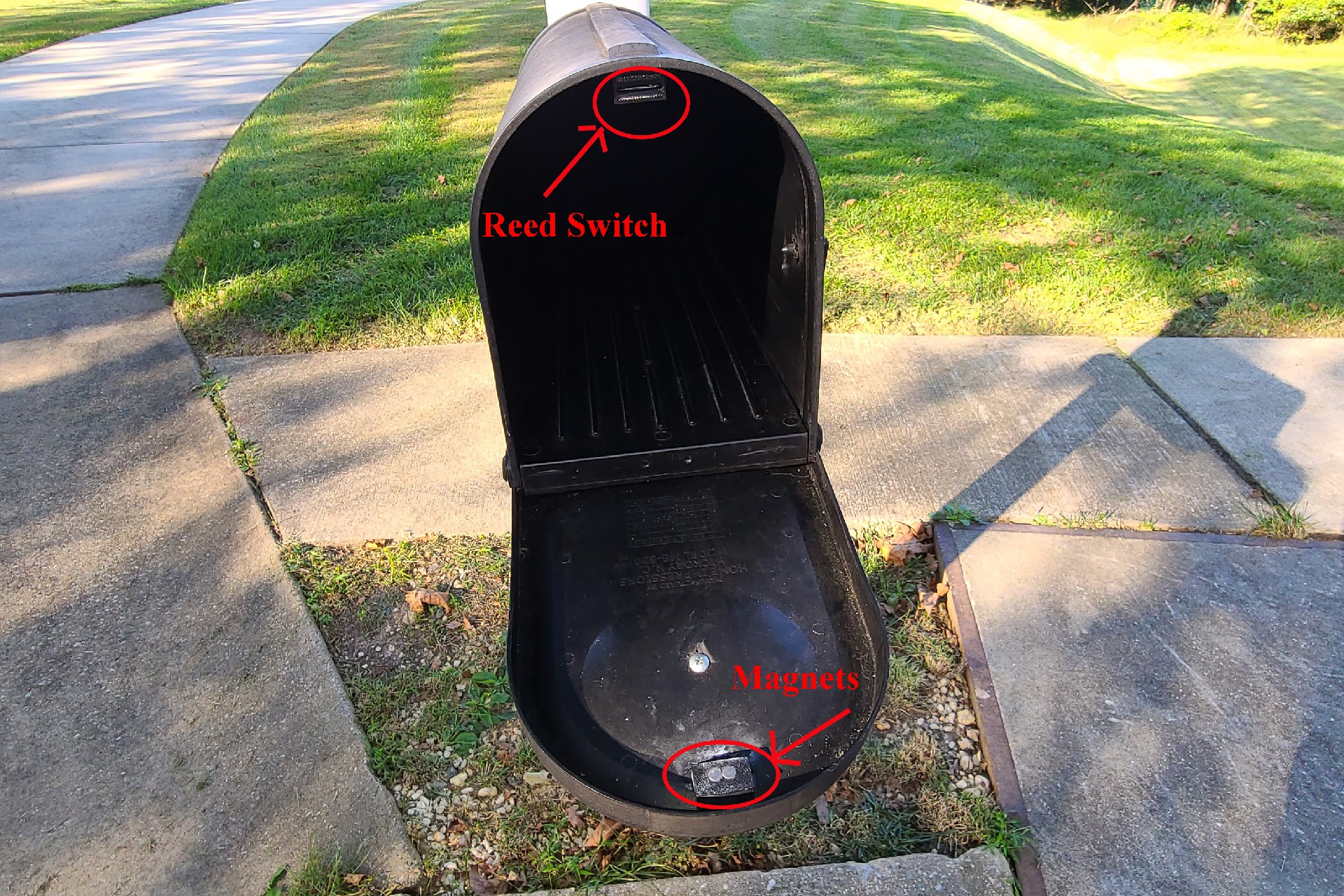
The reed switch is normally closed, so that, when the mailbox is closed, the magnets engage the reed switch and open it, letting no current flow. The 3D printed holders for the magnets and switch are just glued in place, along with a wire channel glued across the top of the mailbox to guide the reed switch wires to the back of the mailbox.
![]()
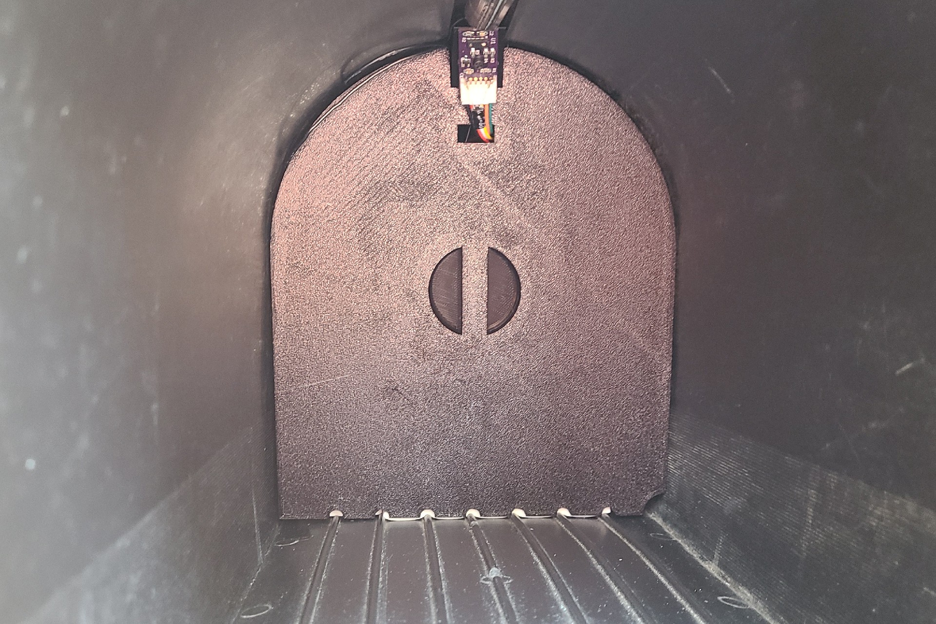
This is a picture of the false back in place in the mailbox.
![]()
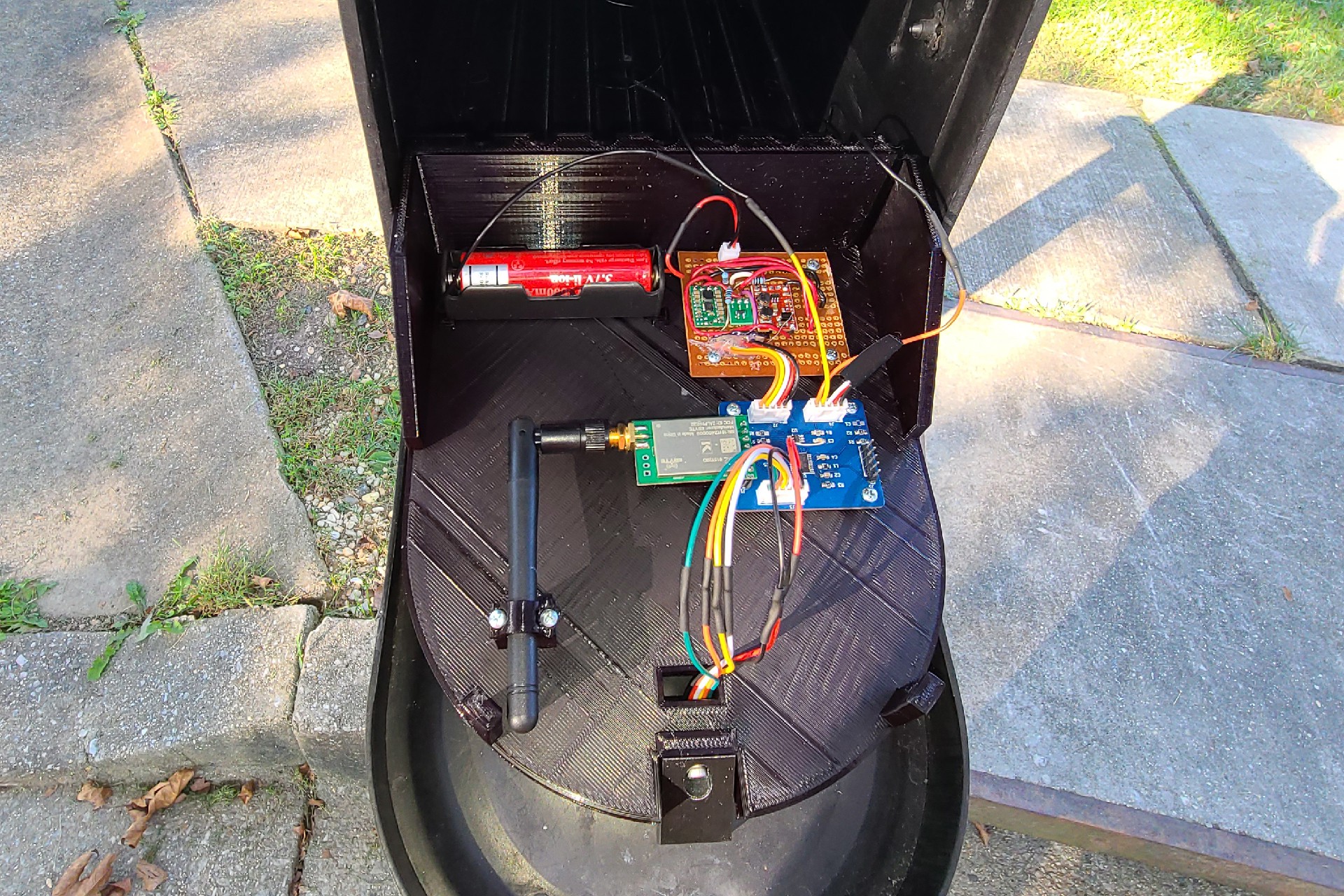
This is a picture of the electronics housed in the false back of the mailbox. The blue PCB is the processor board with the STM32L0 chip, and the perf board contains the 3.3v buck/boost converter and the 5V boost converter. The bundle of wires going through to the front connect the proximity sensor to the processor board.
![]()
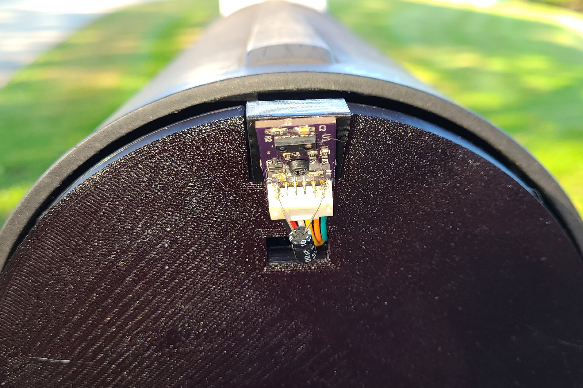
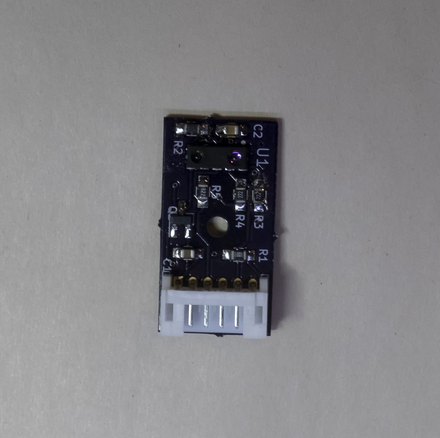
This is a close up of the proximity sensor on the front of the false back, which fits nicely into the groove on the top of the mailbox. The capacitor bodged onto the PCB is across the 5 V supply for the IR LED. This helps supply the high current pulses required by the IR LED.
-
Continuation of the Project
09/22/2020 at 20:50 • 0 commentsAfter a bit of a hiatus, I picked this project back up and have a working prototype. It has been working for about a month and a half, and it has worked amazingly well. The VCNL4200 proximity sensor has worked nearly flawlessly, missing only 1 small piece of mail that was placed very close to the front of the mailbox, and hence, out of "view" of the sensor. Adjusting the angle the sensor is mounted would probably fix that.
That being said, there have been changes and issues, since the original planning of the project.
The flag position sensor was remove because I could not find a way to install it robustly enough to prevent it from getting knocked off during use. It was there so that the mail box sensor could tell if we put mail in the box for the mailman to pick up but mailman doesn't put it down when she takes the mail away anyway, so it would not have been a very effective indicator anyway.
The power supply PCB turned out to use way too much quiescent current to be useful for a battery powered system, so it had to change. I will be logging about the power supply separately.
The mailbox system has been integrated into Home Assistant. Home Assistant gives a simply way for me to monitor the battery level and log when my mail comes (between 12:30 and 1:30 everyday) and eliminates the need for Loggly, Thingspeak and AWS Lambsa. Originally, the mailbox indicator, mounted in the garage, was made to been seen when I returned from work, so I knew to go get the mail or not. With COVID-19, and not going into work for 6 months, I don't get to see the indicator often, but Home Assistant made it very easy to add SMS texting when the mail came. I will be creating a log about Home Assistant integration in the future as well.
-
Power Supply
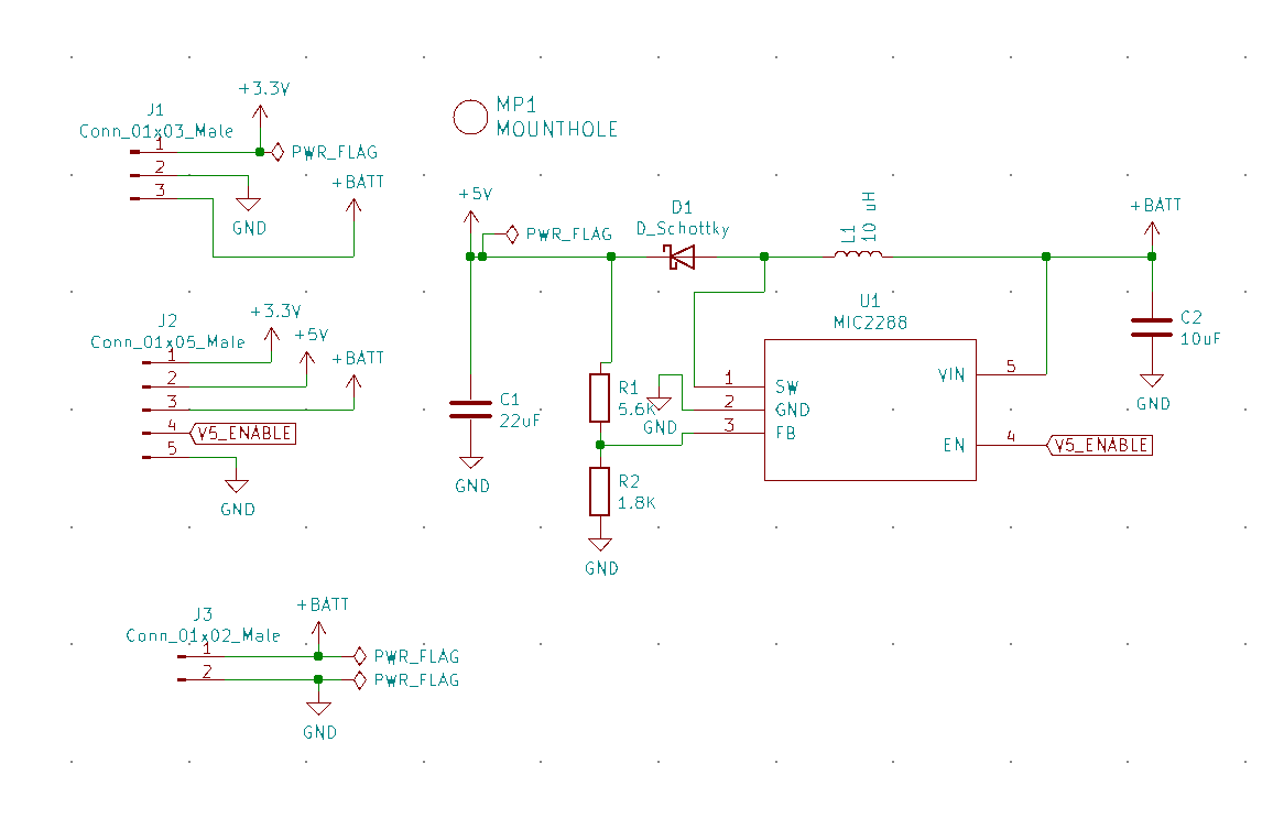
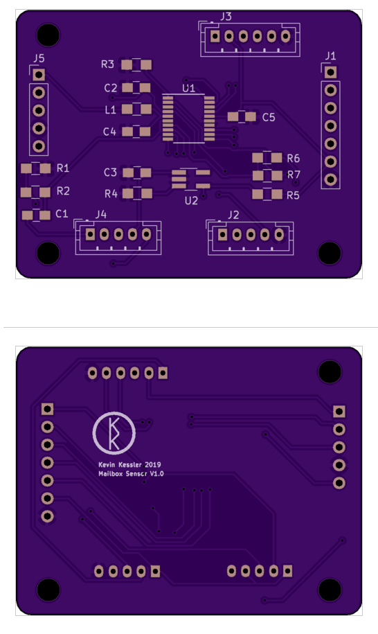
08/09/2019 at 23:02 • 0 commentsThis is the Schematic and PCB for the Power Supply powered by an 18650 battery. Unfortunately, it turned out to have too high quiescent current, and could not be used.
Schematic
![]()
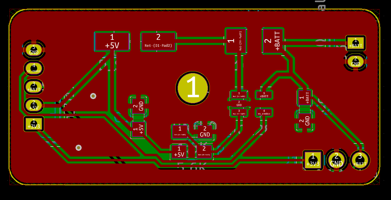
PCB
![]()
-
Mailbox Sensor PCB
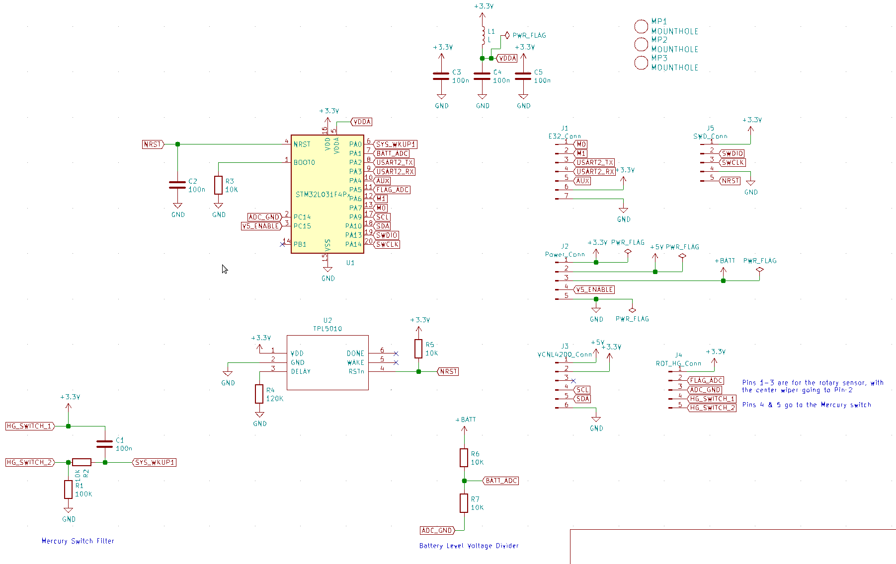
08/09/2019 at 23:01 • 0 commentsThese are the schematic and pcb design for the CPU board.
Mailbox Schematic
![]()
Mail PCB
![]()
-
Proof Of Concept Successful
07/24/2019 at 01:44 • 0 commentsI've successfully tested a taped together version of the mailbox sensors and a pretty complete version of the base station and have documented it in this video:
My video presentation skills leave a lot to be desired.
-
The VCNL4200 Proximity Sensor
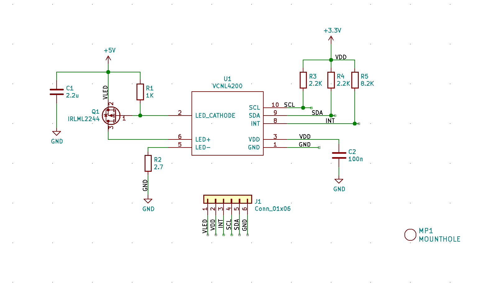
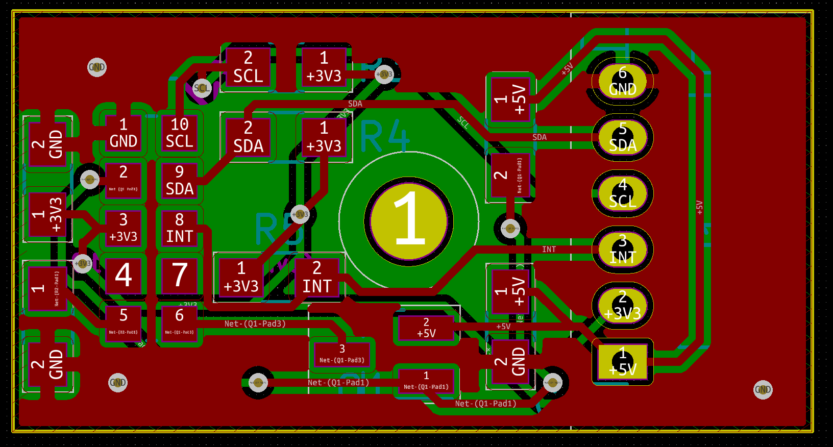
07/24/2019 at 01:42 • 0 commentsThe VCNL4200 Proximity Sensor is an IR LED and IR receiver in a single, very hobbyist unfriendly, package. It also contains an ambient light sensor, which I do not use in this project. The package requires 2 power supplies; a 3.3v one for the controller, and a 5V power supply to drive the LED. An external MOSFET and current sensing resistor are required for the device to control the current through the IR LED, and this current, along with the duration and number of pulses per sense, is configured through I2C.
![]()
I configure the device to run the sense on command (as opposed to the default continuous mode), and is configured for the max 800mA current for the shortest interval and 2 pulses. I haven't tried to optimize these setting for current yet, but they seem to be a good compromise of current usage and consistent detection of paper in the mailbox. This application note on using the VCNL4200 is very good, and would be required reading if you wis to use this device.
The schematic and PCB layout are in a github repository.
![]()
![]()
-
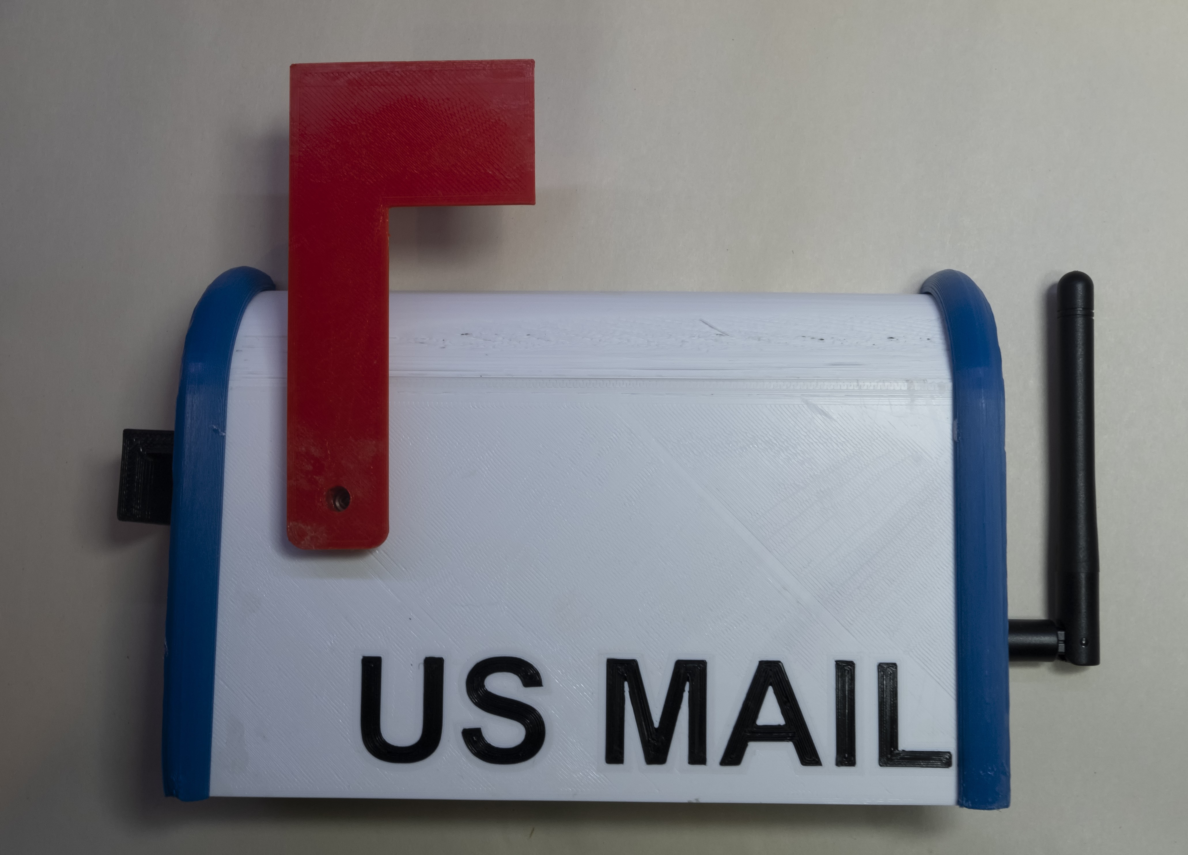
The ESP32 Base Station
07/24/2019 at 01:14 • 0 commentsThe ESP32 base station receives the Lora transmissions from the mailbox sensors and indicates the state of the mail with a servo attached to a flag. The base station also forwards the state of the sensor to the MQTT server for further processing. The MQTT server logs the sensor values to loggly.com, and plot the temperature and voltage data on Thingspeak. The base station also periodically sends a heartbeat to the MQTT server (indicated by a sensor value set of all the lowest values). The MQTT server monitors this heartbeat, and will text my phone if the heartbeat goes missing for long enough.
![]()
The base station code is written in the Arduino core. I normally avoid the Arduino programming model, mainly because I despised the Arduino IDE. I've discovered the PlatformIO IDE, and I'm pretty happy with it; so much so that I've written the STM32 CubeMX code for the Mailbox Sensors with it as well, instead of Eclipse that I use for pretty much everything.
In order to configure the device, a SPIFFS file system is created with a JSON file that looks like:
{
    "ssid": "xxxxxxxx",
    "password": "xxxxxxxxxxxx",
    "pskIdent": "xxxxxxxxx",
    "pskKey": "xxxxxxxxxxxxxxx",
    "mqtt_host": "xxxxxxxxxxxxxx",
    "mqtt_port":  8883
}
This is filled out with the wifi credentials and the pre-shared key and address of the MQTT server, and saved to the data directory. The github repo contains this file in a data_model directory, but the actual filled out version must go into a data directory at the same level. I do this so I don't accidentally upload my wifi credential to github. The SPIFFS file system is uploaded separately from the code with the command:
platformio run --target uploadfs
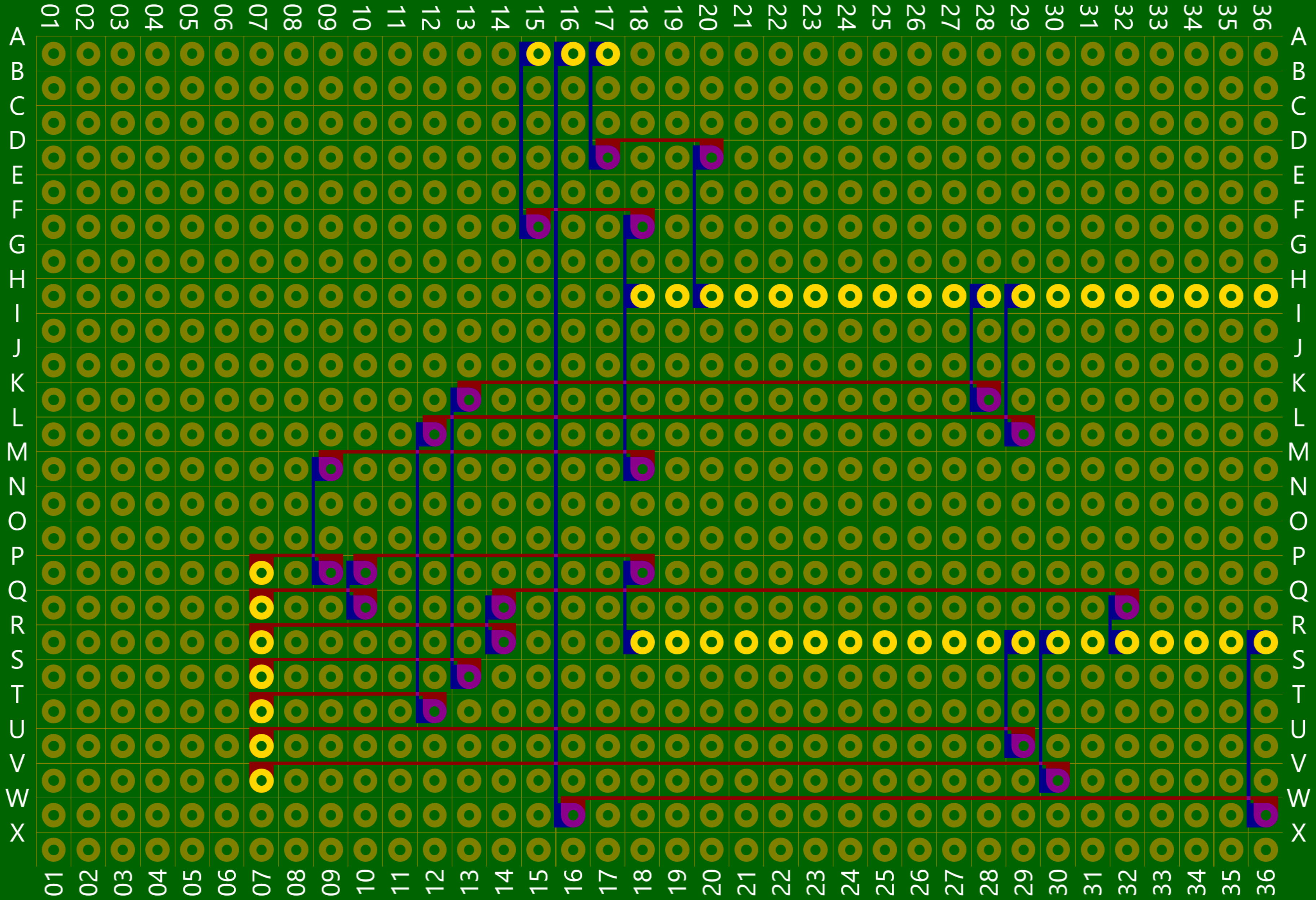
The PCB is rather large and would have been expensive to get created at OSHPark so I decided to try some Perf+ boards boards I had lying around. The Perf + PCB uses perpendicular traces and solder bridges to route signals between endpoints. The software Perfy assists in routing traces and deciding where to put the solder bridges.
![]()
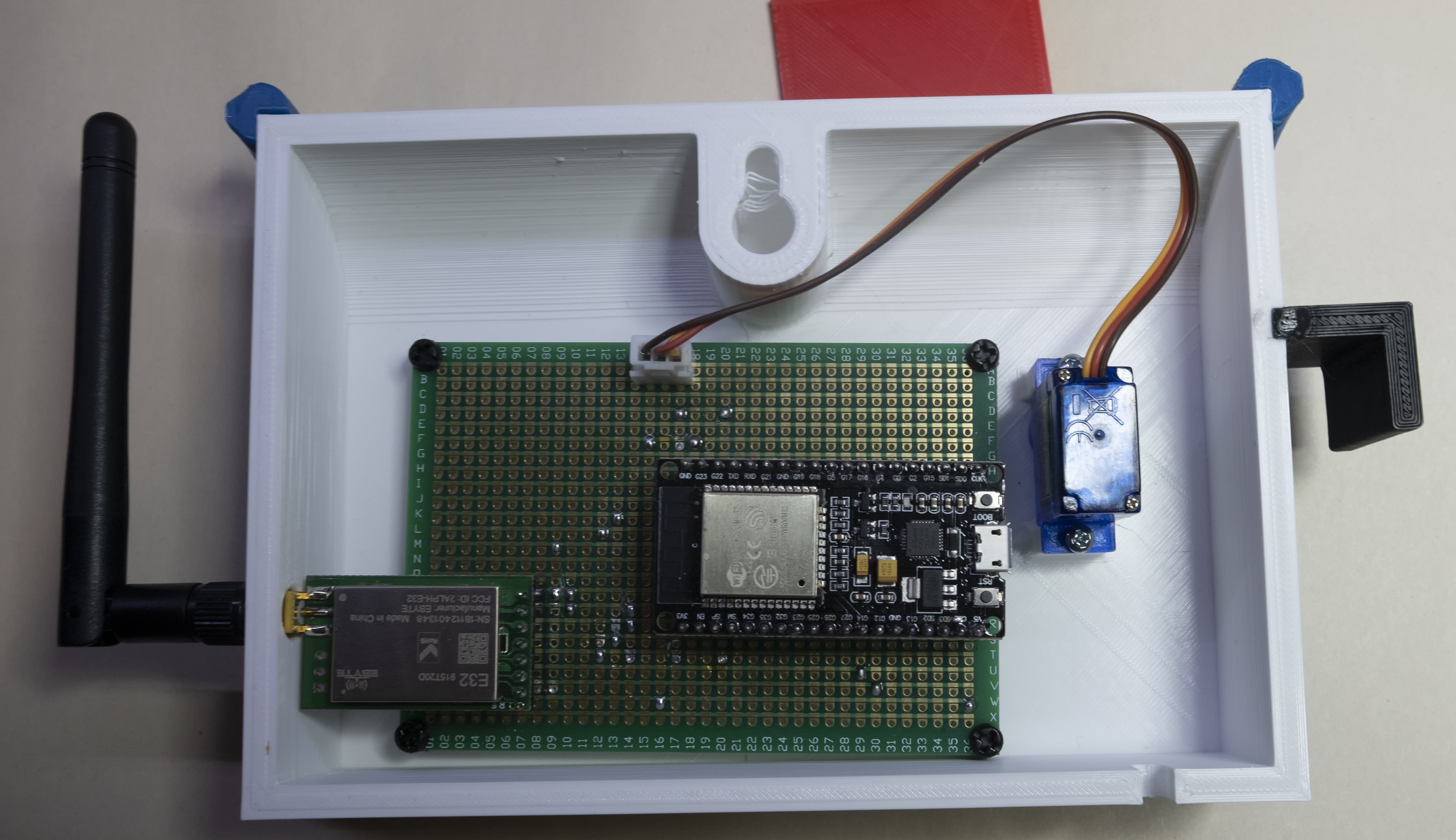
This type of PCB works because the circuit for the base station is so simple. An ESP32 Dev Board drives an E32 Lora Module through the second UART, and a servo runs through PWM of a GPIO.
![]()
Mailbox Sensor
I'm tired of walking the whole way to my mailbox to see if there is mail in it, so technology comes to the rescue