Close
0%
0%

Core 64: Interactive Core Memory Badge

Weave your own Core Memory to learn and hack!

Similar projects worth following
Draw with a magnet directly IN CORE MEMORY!

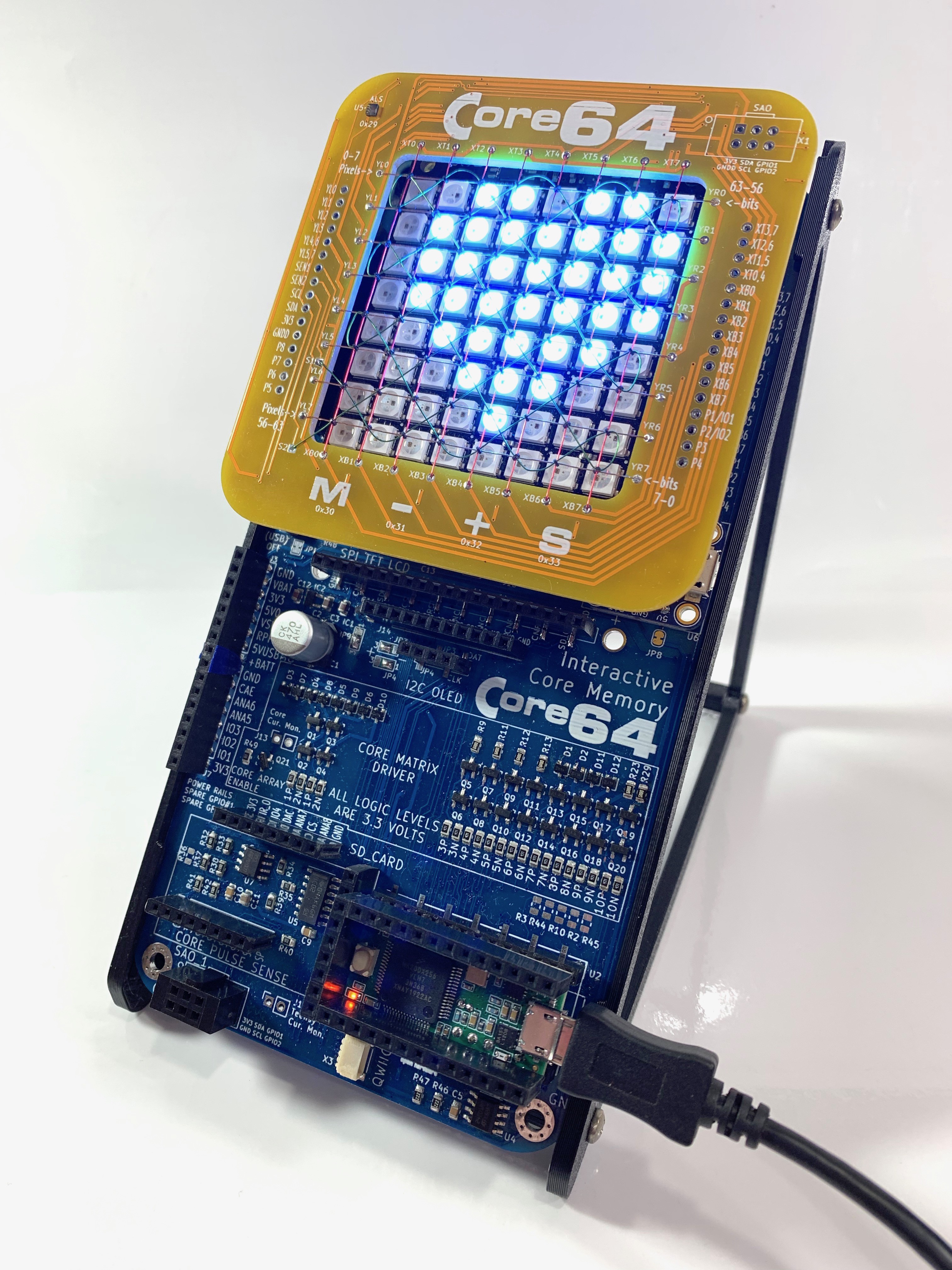
Many people may have heard of core memory (most recently with the buzz surrounding the Apollo Guidance Computer) but few have experienced it. This project enables interaction and education using core memory that is unexpectedly engaging with the door wide open for more exploration. With this project in hand, you will be able to physically interact with core memory using a magnet. You simply have to try it! The array of LEDs underneath brings the cores to life in a completely new way. You will be able to create your own core/light interactions in the Arduino environment.

This is one of those ideas that seems too simple but needs to be experienced to get it. Based on the feedback I have received from people who have used the proof-of-concept, it is clearly worth sharing with a wider audience as a complete product. The form factor begs for this project to take shape as a badge because it is easier to carry around and share the experience.

The previous work with the proof-of-concept is posted here and runs with 32 cores. The badge kit version of this project is taking shape on this project page and has 64 cores. The project name is a nod to my favorite 8-bit computer, the Commodore 64. A formal home for Core64 has been established at www.Core64.io (Beta kits for sale!)

What does it do?

I just added a VCF West 2020 virtual exhibit video which is a good summary of the project so far.

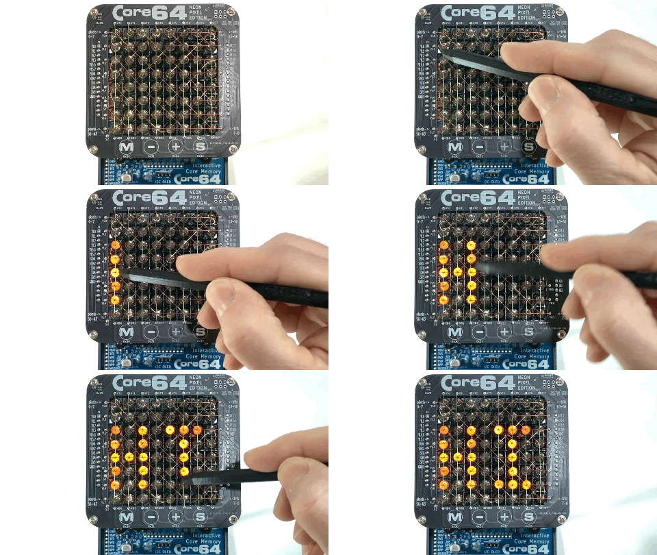
It allows you to draw in core memory with a magnet like this...
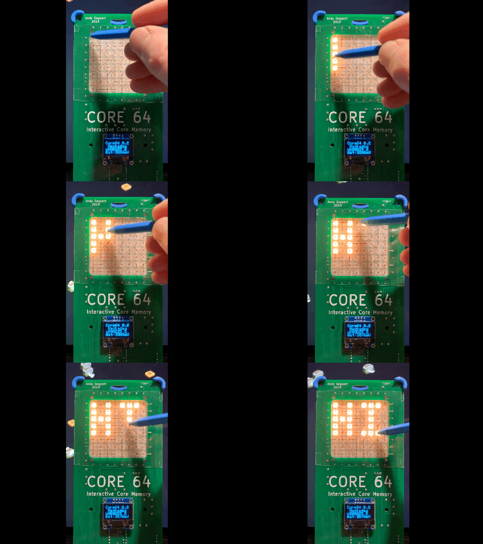
...and MUCH more. It is designed for learning and hacking. You can easily apply your creativity through the Arduino IDE with just the standard kit.

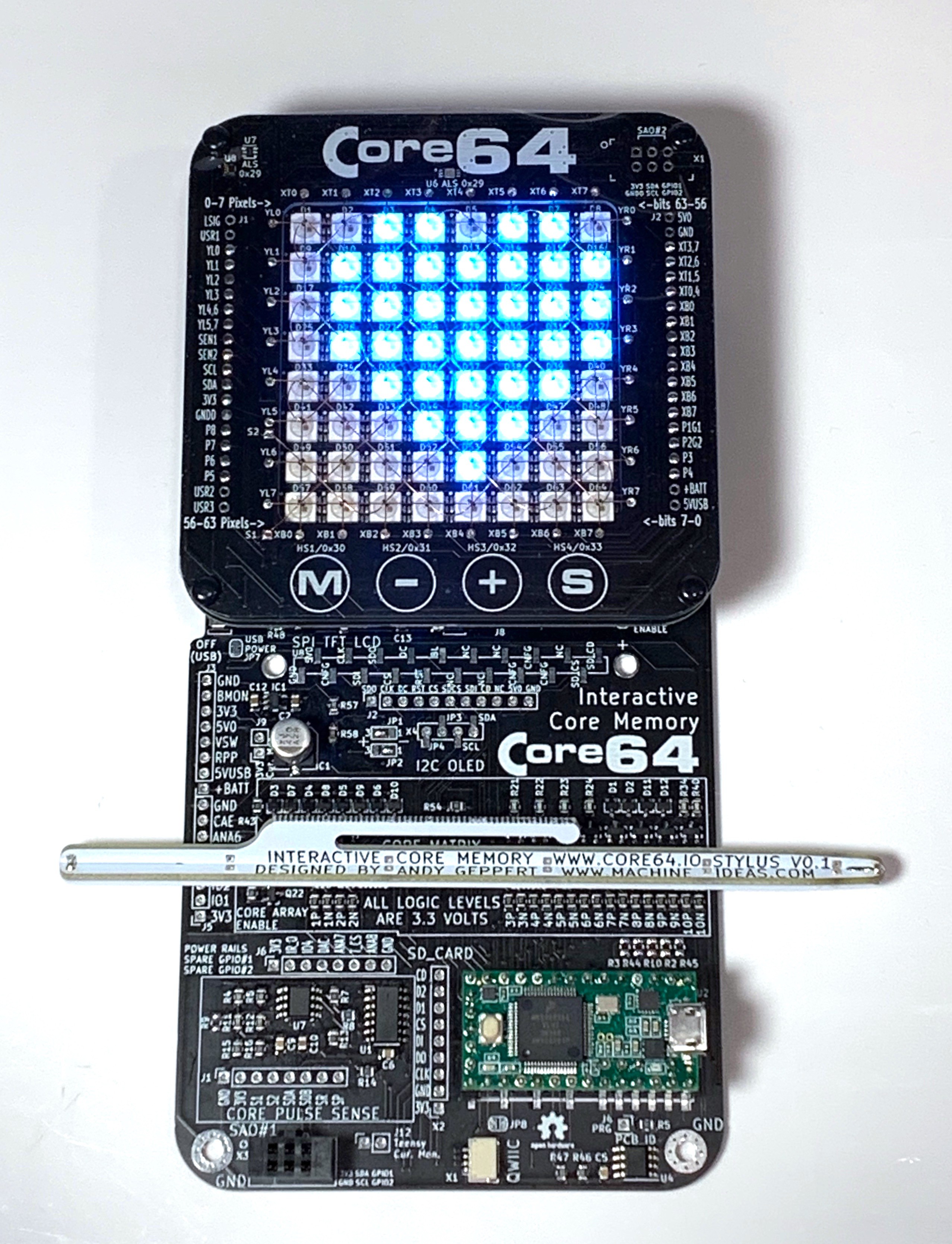
Here is a video demo. In its simplest form, the badge allows you to draw on the RGB LED matrix "screen" with a magnetic stylus. In this first mode, you are directly interacting with the cores which are acting as static screen RAM. It is that simple but it ends up being very engaging on its own. When I share this with people, this is where I start to hear, "Oh, this is cool. Now I get it." At this point you are only seeing a monochrome drawing mode.

There is another mode of operation that enables a much wider range of interaction. In the second mode, the cores are acting as a touch overlay on the RGB LED screen. The cores are effectively acting as "touch RAM." By refreshing and checking the state of the cores, the whole array comes alive and can sense which core (or cores) are being affected by a magnet at a given moment. By decoupling the cores from the screen RAM, the creative juices can be unleashed. Instead of a monochrome drawing mode, full color drawing can come alive. The core array turns into a mesmerizing magnetic flux detector. I have even implemented a simple game of snake that is fun to play.

I need to make a technical clarification for those who know the intricacies of core memory operation. In the present implementation, as far as I can tell, the magnetic stylus is not changing the core polarity to a specific direction. Instead, it works by inhibiting the first write in the read process by holding the core in a fixed polarity so the sense wire doesn't see the effect of a polarity change when the core is written too. This is because the strength of the magnetic field in the wires is not enough to overcome the presence of the stylus magnet. That fixed polarity could be either CCW or CW. I need to do some more testing to clearly understand how it works. For now, it works very well in this mode of operation, but it requires constant scanning of the core array to see the stylus. This makes me think more about an active stylus add-on, or stylus with each end having an opposite magnetic polarity.

Beyond the "core memory + LEDs" party trick, I have several other goals for this project. Here they are, along with the reasoning behind why I think they are valuable:

Deceptively Simple

My aim is to keep the badge clean looking from the front so the focus is entirely on the cores and LEDs themselves. That is, after all, the focal point of this project. Everything will be accessible from a mechanical/electrical/programming perspective which leaves the door open for your creativity to be expressed.

Full Control of the Cores

I made a conscious decision to use a microcontroller to discretely drive the core wiring matrix with transistors. This allows you to develop your own control algorithms and have complete control of each wire in the core matrix to really learn about what is happening. I have seen other projects which decouple the addressing logic through hardware which makes it easier to interface with the cores, but the point of this project is to get you as close to the cores as possible. You can choose to abstract the interface as much or as little on the software side.

Hidden [Magnetic] Tricks

In order to open the door even wider to your creativity, and sticking with the spirit of a project which revolves around magnetism, there...

Read more »

Software Block Diagram.pdf

Adobe Portable Document Format - 29.86 kB - 08/25/2019 at 12:26

Preview

Manufacturing Considerations.pdf

Adobe Portable Document Format - 52.61 kB - 08/25/2019 at 02:59

Preview

Licensing and Permissions.pdf

Adobe Portable Document Format - 68.01 kB - 08/25/2019 at 02:59

Preview

Development Plan.pdf

Adobe Portable Document Format - 34.86 kB - 08/25/2019 at 02:59

Preview

Code-Read and Write Cores.pdf

Adobe Portable Document Format - 96.65 kB - 08/25/2019 at 02:52

Preview

View all 8 files

  • Core64 Beta Kits Shipping Now!

    Andy Geppert04/30/2021 at 02:38 0 comments

    This milestone was a long time coming! I'm finally releasing some of these into the wild for you early adopters to get your hands on experience... and provide me some feedback!

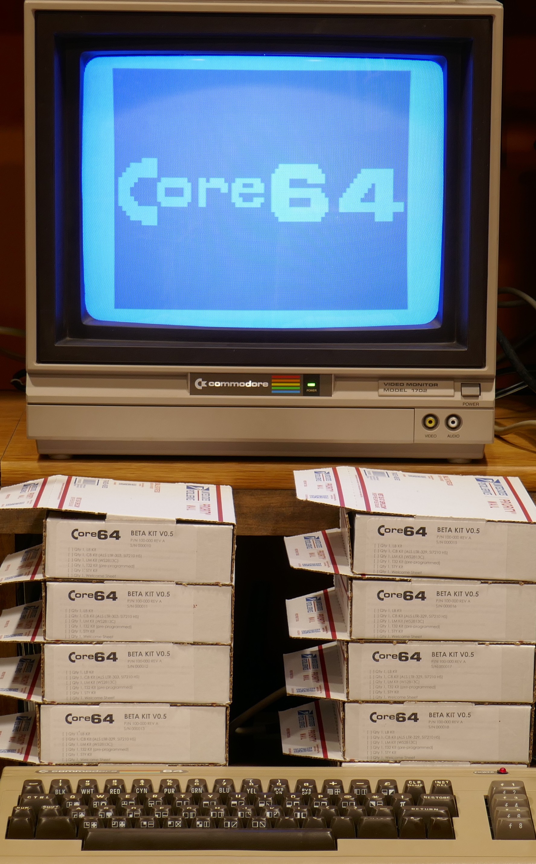
    I won't make you log in to a BBS to buy a Core64 Beta Kit. Instead you can do that at www.Core64.io.

    I look forward to feedback so I can polish the product a bit. For now, I have to switch gears to get some real manufacturing set up, and give the firmware some attention so users can get into it quickly and create their own interactive core memory experiences.

  • Core64 Beta Kit Assembly Update

    Andy Geppert04/10/2021 at 22:18 0 comments

    I am closing in on completing 10 beta kits... This reinforces the idea that I do NOT want to do production myself. Even with robots.

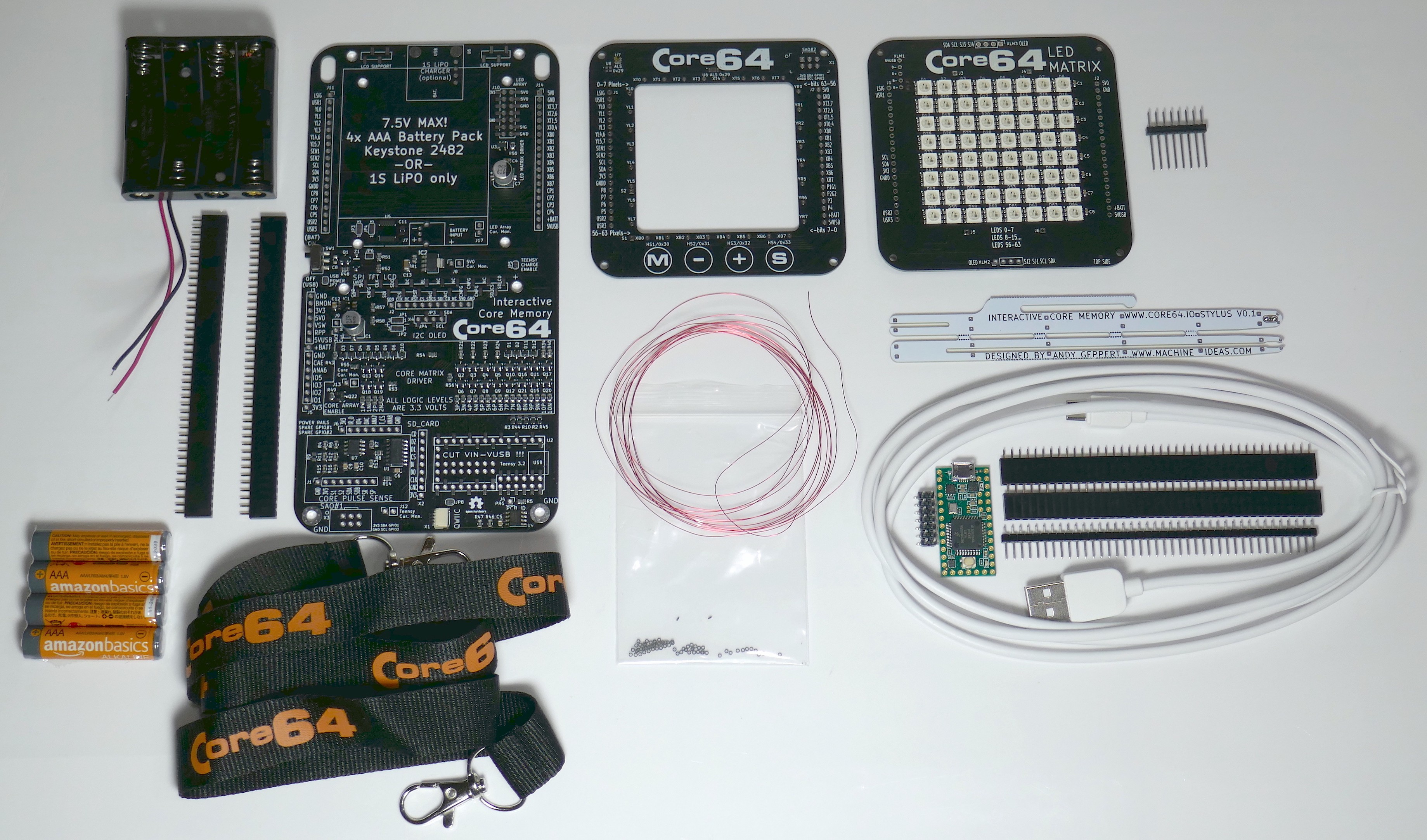
    The kits are coming together nicely, especially since I switched to a custom LED Matrix board. The fit is just perfect and I'm very happy with it. The kit has 5 different subassemblies: Logic Board, Core Board, LED Matrix, Teensy 3.2, Stylus. It's a lot of work to pull all of this together, but the results are worth it.

    Another change I made was the introduction of a magnetic stylus made from a PCB. It goes together well, and completes the kit without any 3D-printed parts. Yes... the recipient of the kit gets to assemble the stylus too! There are two magnets captured in the tip. The stylus is completely passive. Here are all of the parts of the kit:

    If you'd like to be the first to know when the beta kits go on sale, please sign up at www.Core64.io.

  • Core Memory + Neon Pixels

    Andy Geppert01/03/2021 at 13:54 0 comments

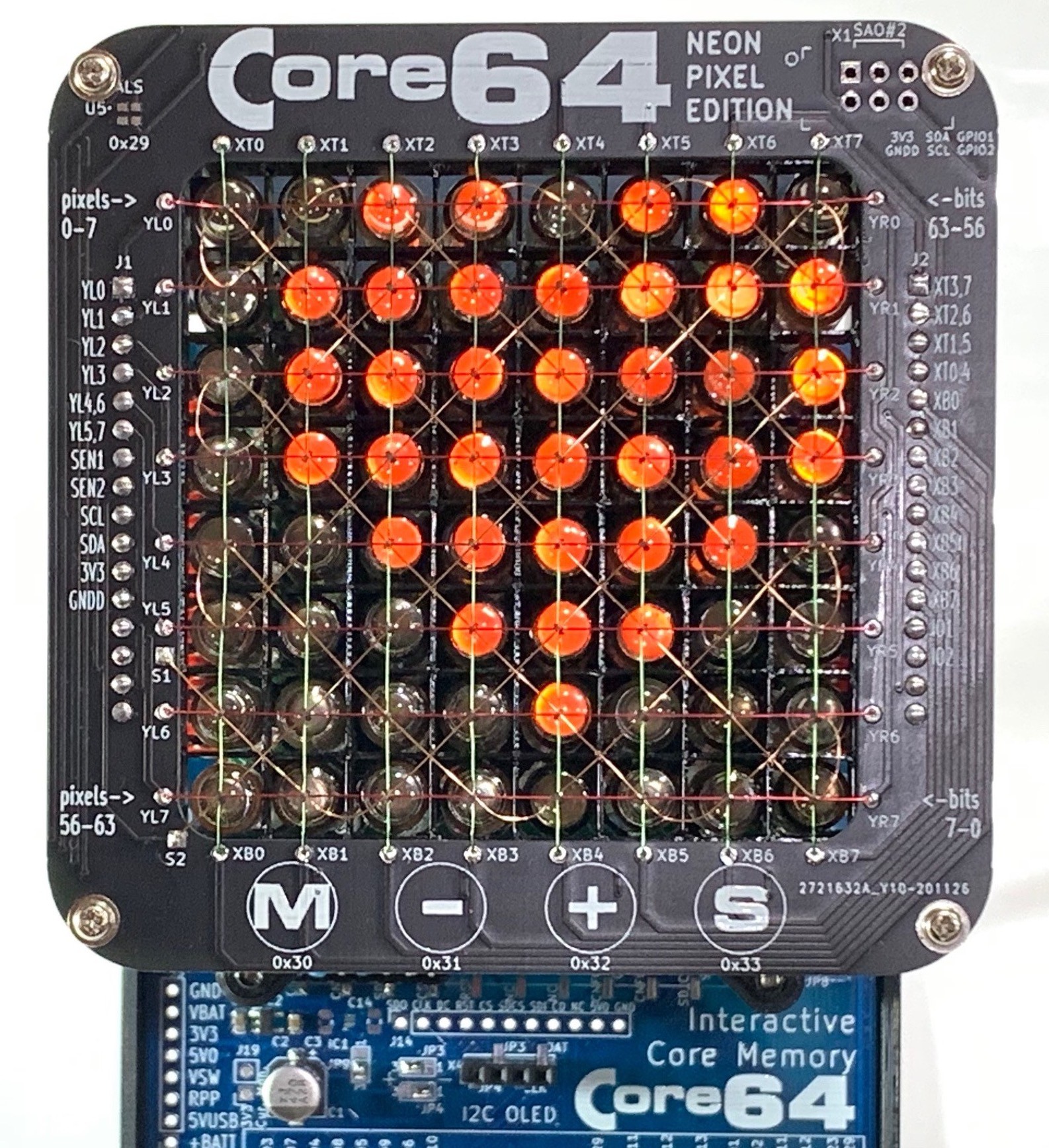
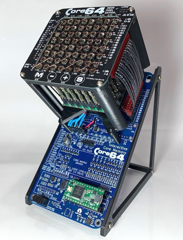
    While browsing Hackaday.io I found an opportunity to collaborate with [Muth] and we put Core Memory and Neon Pixels together. They seem to be made for each other:

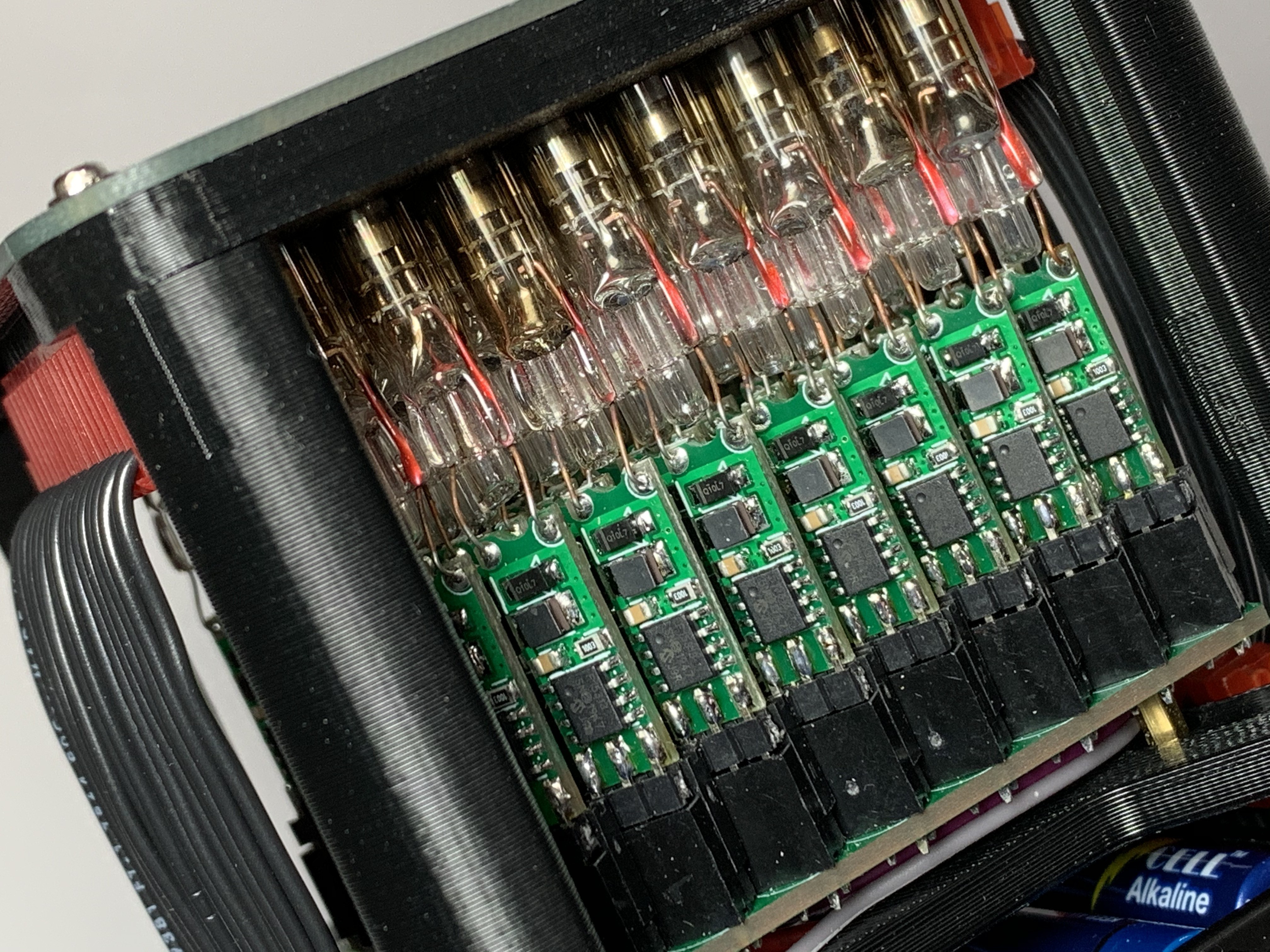
    [Muth] built a fantastic project which stands on its own with hundreds of hand-crafted Neon Pixels. Both the individually controlled pixels and the combined 8x8 arrays are works-of-art on their own. I thought they would make a great match with interactive core memory, so I made a "Neon Pixel Edition" prototype with help from [Muth] .

    Neither of us plan to make the Neon Pixel version available for sale, but it was a very satisfying project to combine our projects. Look for me at the next VCF and try it out! If you'd like to make your own Neon Pixels, all of the details are available at Github. There are a few references to these INS-1 tubes on Hackaday. Sometimes they show up in Nixie tube clocks, and they go by various names like Nixie tubes, neon dot bulb, ИНС-1, neon lamps or bulbs. Seems like they were manufactured in the 80's, but I haven't found much information on them. If you know more about their history, please share that in the comments. 

    I'm still moving forward with the basic configuration of the Core64 kit which uses RGB LEDs:

    I plan to have 3 Beta Kits available for sale shortly so that I can get some hands-on feedback. If you'd like to provide some feedback now, please fill out the form at the bottom of the page at www.Core64.IO.

  • Latest Core Board Assembled - Design Lock is within reach

    Andy Geppert11/06/2020 at 02:18 0 comments

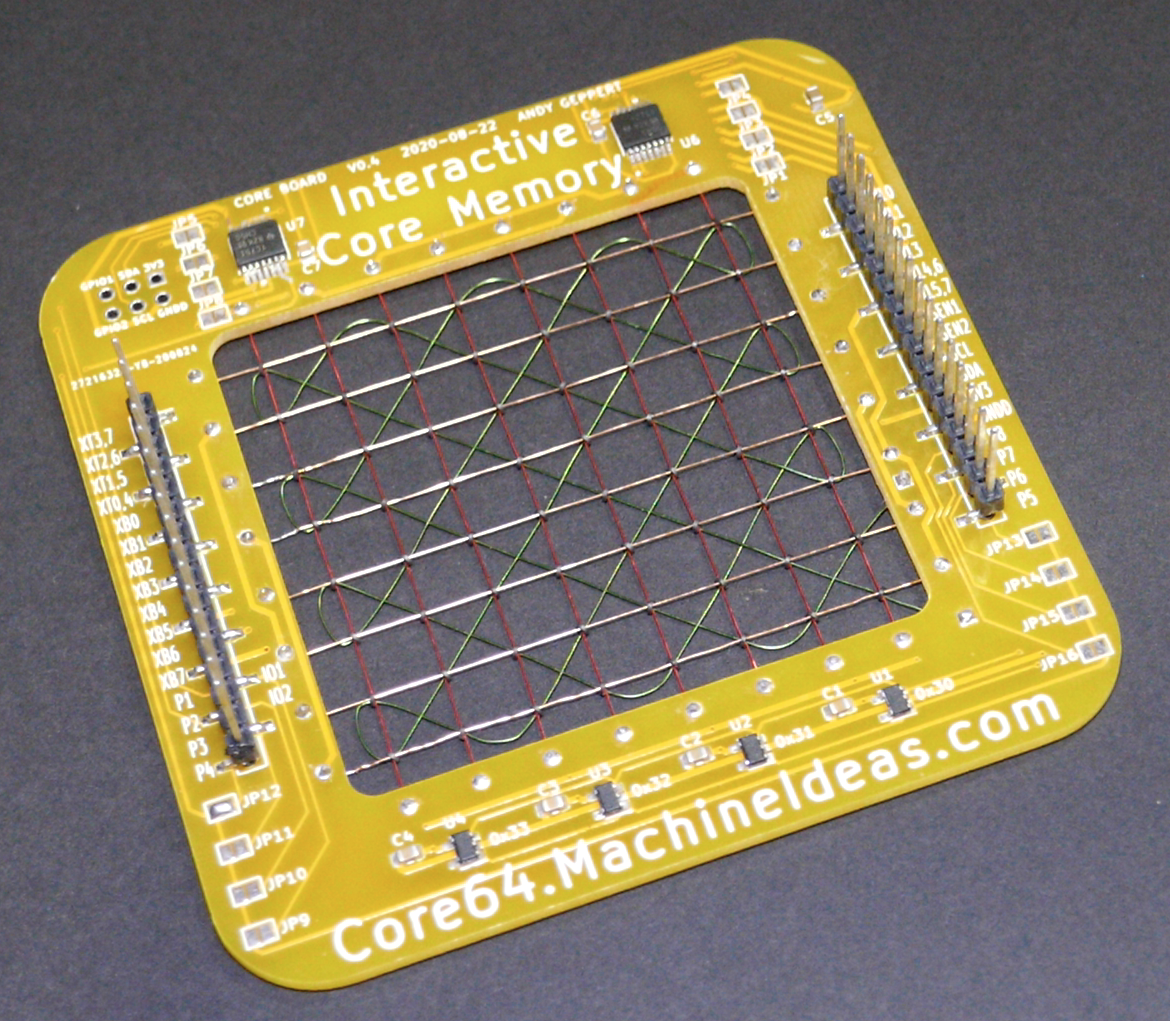
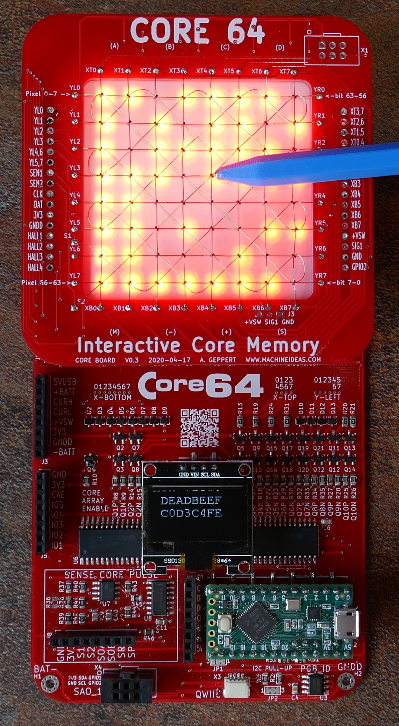
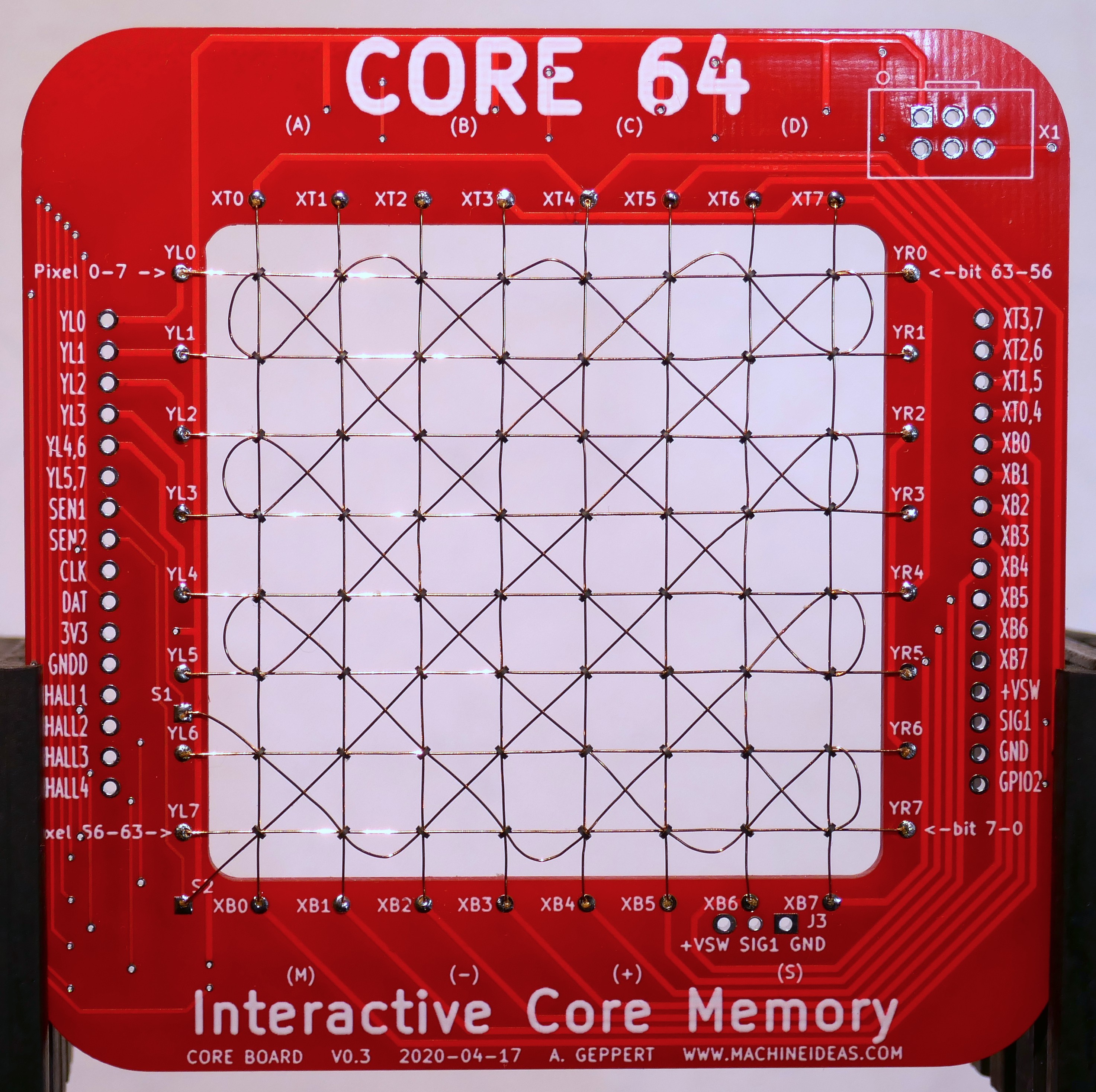
    This what I think will be the final core board configuration. 

    All of the functionality is tested, except I haven't physically made a core stack yet. I'm happy with the ambient light sensor and hall sensor "buttons" hiding under M - + S. The layer select function works well too, composed of solder jumpers and the two big chips in the top of this photo:

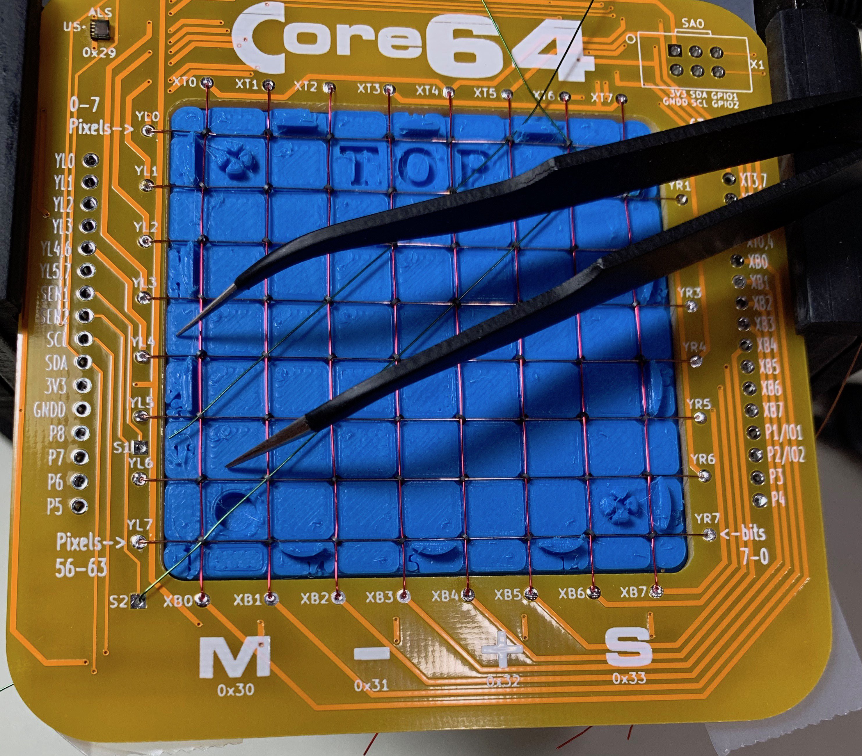
    I'm also quite happy with the weaving in this one. This is my best one yet thanks to a 3D-printed assembly fixture. The fixture helps guide the sense wire crisply. My vision of making the cores easier to thread by placing the fixture on from both sides of the PCB has not yet been realized, but manually weaving plane isn't too bad... after some practice on the first two.

    In the last project update I thought I could get to the point I have 8 of these stacked by now, but other priorities called. I will get these stacked after I complete the Logic Board layout. I'm reviewing the schematic now and wrestling with which features to drop from an over-crowded board. This board WILL have the ability to drive all 8 layers of core planes, and that is going to be fun when I get all the core planes visualized in real-time on an LCD!

  • Time for another round of prototypes

    Andy Geppert08/27/2020 at 04:00 0 comments

    I've kicked off another round of prototypes with what I think is the final configuration. I'm sticking with the dual board design.

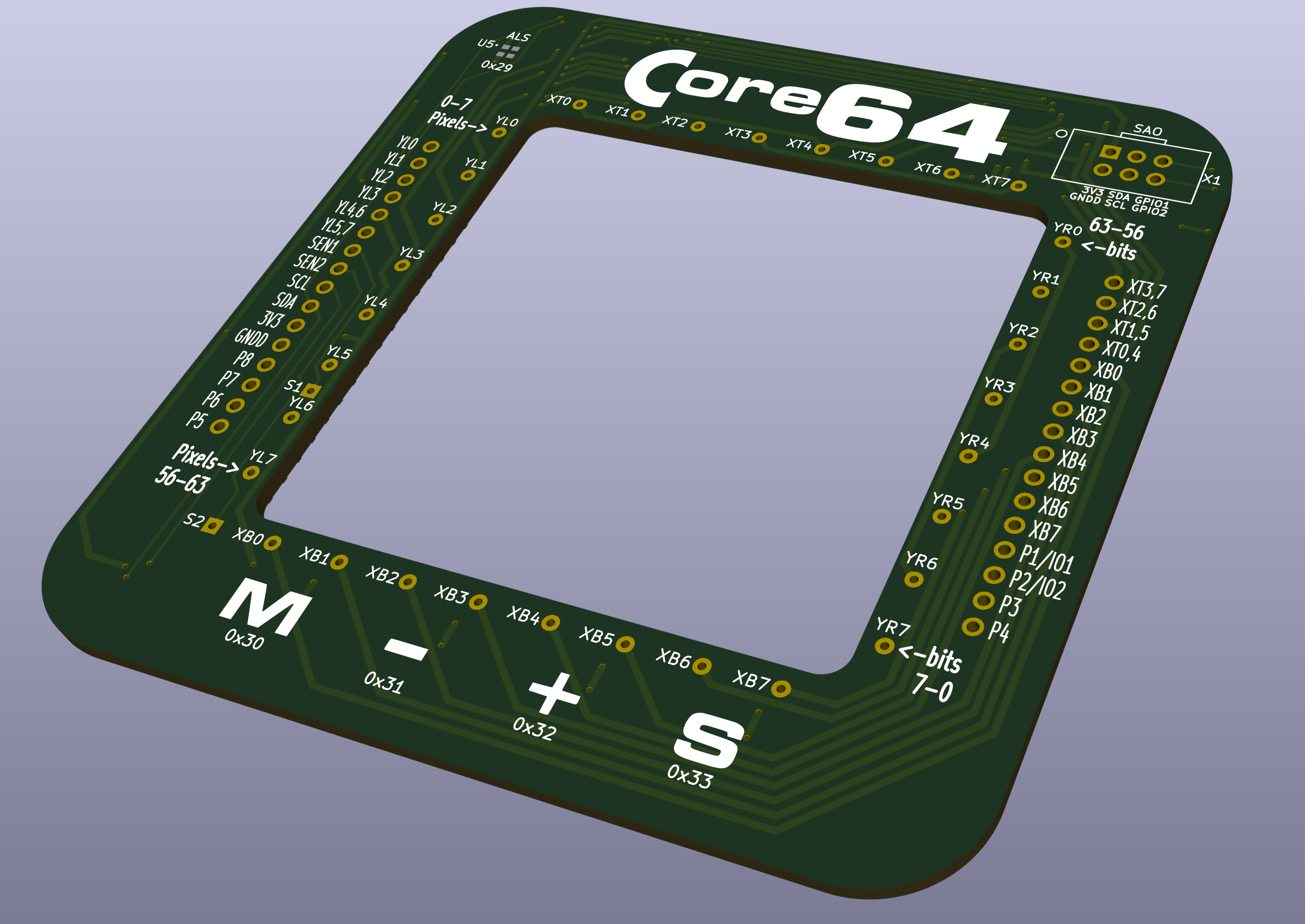
    The top Core Board will have four I2C hall sensor buttons in the bottom edge of the frame to enable more flexibility with the user interface (Mode, Set, Minus, Plus). The hall sensors read flux strength, and that makes the sensitivity tunable versus the hall switches which use a fixed flux level for activation. I am also now including an ambient light sensor (upper left corner of this rendering) to automatically adjust the LED array brightness. The LEDs in the LED array have a dynamic range that needs to be adjusted for dim and bright conditions or they end up being blinding in low light, and unusable outside in the sunlight. 

    There are also some traces and pads to allow me to experiment with stacking 8 core planes on a single logic board. Look for that as an entry in the Circuit Sculpture Challenge. I've got something unique planned for that. 

    EDIT: I was not able to dedicate enough time to this project to enter the contest... But I'm still making progress on the goal of stacking 8 planes. See the next update for more details.

    The core boards and components are ordered and should arrive this weekend.

    The logic board is next for update work. I have a long list of refinements pinned down, and schematic refinement will begin in the next few days. The highlights:

    • Stepping up to a Teensy 3.2 because the LC doesn't have enough IO.
    • Removing the slow IO expanders, so core scanning speed will be greatly increased.
    • Increased usable battery voltage range of ~2.8 to 7V (1S Lipo up to 4 primary AAA or AA Lithium cells)
    • Using much lower drop-out 5V and 3V3 regulators to make better use of the batteries.
    • Creating more room for expansion by exposing several I2C and SPI pins for optional fun stuff: 3.2" LCD to replace LED array, Monochrome or Color 128x64 OLED, 128x32 Teensy View OLED, Micro SD Card, 2x SAO ports, and a QWIIC port. 
    • The battery area will accommodate being powered with an optional 1S LiPo and charge manager for those who prefer not to use primary cells.

    An expansion option that I'd like to see offered is the ability to communicate between badges with magnetic fields. The first choice would be NFMC like the Defcon 27 Badge. I've also see some 3D flux sensors (Infineon) that might work, and I've considered a PN532 Breakout Board. If you have some interest in bringing something like that to life for this project, I'd like to hear from you.

  • Features and Accessories Questions

    Andy Geppert07/30/2020 at 03:14 0 comments

    I have a lot of ideas for expansion to make sure there is room for easily exercising your creativity. But I need to narrow things down and get a produceable design ready.

    What do you think of these as baseline features that would be included?

    • 64 bits of authentic core memory (weave it yourself)
    • 64 RGB LEDs (Pimoroni Unicorn Hat)
    • 4 hall switches (user configurable)
    • Arduino compatible Teensy 3.2 (32-bit NXP Cortex-M4 72 MHz) with all IO accessible
    • Magnetic Stylus with narrow and wide field tips
    • 4x "AAA" battery pack holder
    • Battery Voltage Monitor
    • All of the matrix drive lines, the power rails, and the sense outputs will be easily accessible

    What do you think of these plans to provide the following header rows/pads for additional expansion?

    • Generic I2C OLED
    • Generic SPI OLED or Sparkfun Teensy View SPI OLED
    • SAO Port, quantity 2
    • Adafruit MicroSD breakout board
    • Sparkfun QWIIC port
    • Ambient Light Sensor
    • Proximity Sensor
    • Sparkfun LiPo manager
    • Generic or Adafruit 3.2" LCD to replace LED Array

    What would you consider the must-haves?

    Any ideas for nice-to-haves?

    If you wouldn't mind providing that feedback through the survey form on my website, I'd appreciate it:

    https://core64.machineideas.com

  • Power Supply Improvements

    Andy Geppert07/11/2020 at 16:03 0 comments

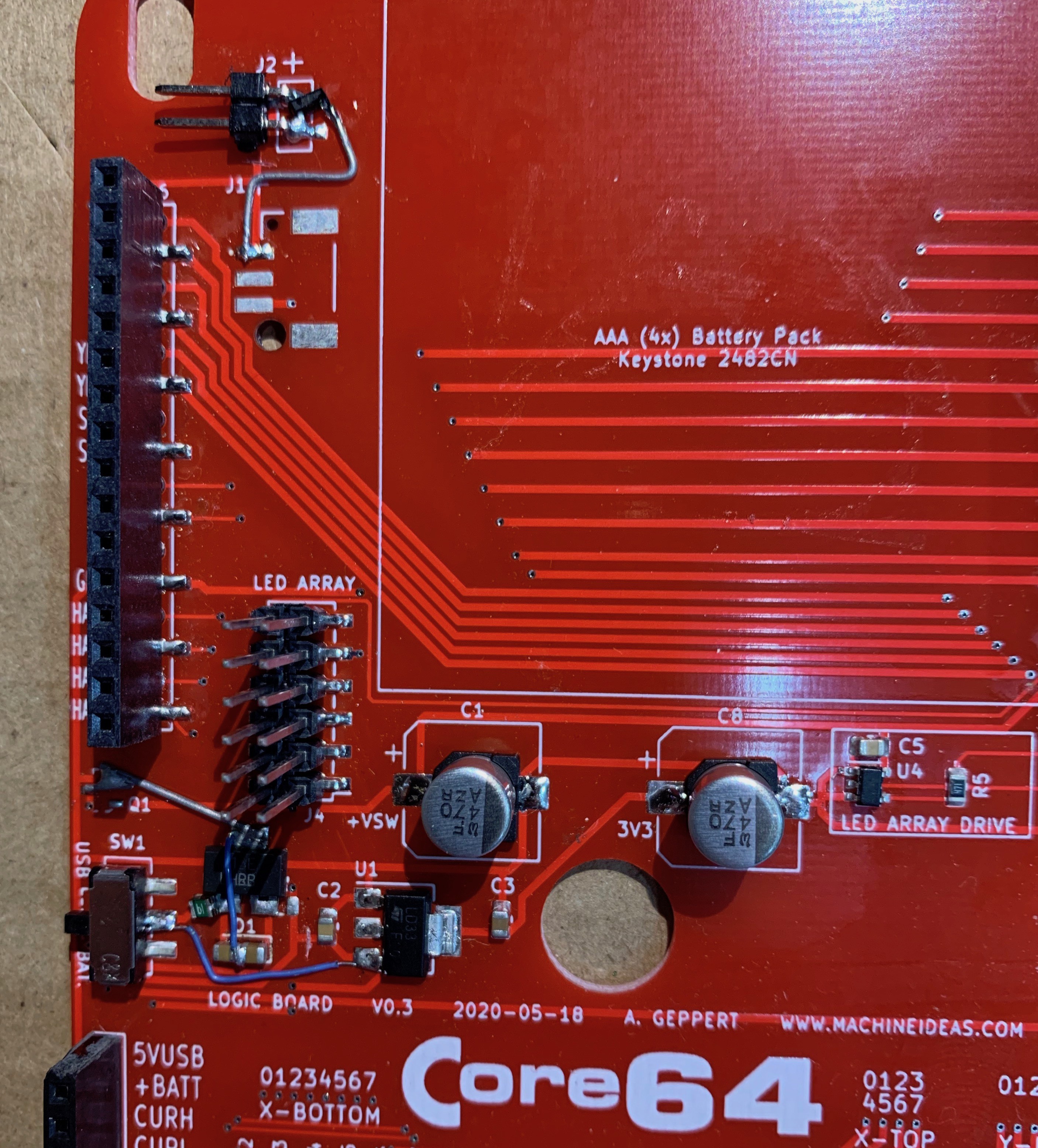
    I made solid progress on power supply and efficiency for the system. Time for another round of "spot the bodge wires:"

    The improvements:

    1. Simplified ground bus: Reverse Polarity protection moved to high side to simplify all grounding.
    2. Reduced voltage drop/waste: Removed diode as RPP, now using only the P-CH FET. 
    3. Increased operating voltage range: Now 3.6 to 7.0 (was 4.5 to 6.0) with these changes:
      1. Added 5V regulator/bus for LED array and Teensy Vin (Teensy LC max is 5.5, Teensy 3.2 max is 6.0)
      2. Allows use of 4x "AAA" batteries like Energizer Ultimate Lithium, because four of them is almost 7V vs. regular alkaline which might be ~6V maximum, which exceeds what the Teensy can handle. I know this by trial and error.
      3. Opened the door to using a 1S LiPo, if the user chooses to hack in that option. I plan to make it easy to hack in with an Adafruit Micro-LiPo Charger.
    4. Improved efficiency: Powering both 5V and 3V3 regulators separately from the battery/switch, not in series.

    Other notable points:

    • The pin/sockets are working well for the Core & LED & Teensy components. Insertion/removal force is "just right" and it makes it easy to hack and modify. I haven't bent any pins... yet.
    • Lots of optional female headers making 'scoping signals much easier than using test point loops.
    • Battery pack behind the core array is out of the way AND supports LED array at the right height under the Core array. Stack-up is "just right."

    Do you know how to configure both the 5V0 and 3V3 regulators to be automatically bypassed when their respective input voltages drop below 5.5 and 3.8? This would increase efficiency and expand the lower limit of the battery voltage range even further. Right now the 1S LiPo only goes to about 3.6 before the system browns out, and it should easily be able to go down to 3.3 or even 3.0 to use the full range of the LiPo.

    Next up, test the hall switches on analog inputs and some optional add-ons (SD-Card, QWIIC light sensor, LCD).

  • Dual Red Board Prototype is Working!

    Andy Geppert07/08/2020 at 02:32 2 comments

    On July 4th I finally got the newest prototype working. But it runs very slowly...

    I chased some rabbits, learned even more, and figured out that the enable transistor has too much of a voltage drop for the system running at 3.3V. With the enable transistor, there are a total of three transistors in series for each core matrix wire. That doesn't leave much current for flipping bits. As a quick test, I soldered a jumper wire to bypass the enable transistor and then everything started working reliably. I've now replaced the transistor with a FET and gate pull-down resistor. It's just above the section in on the left above the chip, above the text CORE ARRAY ENABLE. 

    With respect to the core matrix drive, there are two big functional changes in this prototype from the last one (single green board). And some big "oh..." learnings.

    1) The core matrix is driven from a 3.3V regulator. And it starts to drop-out around 4.3V. And with a .9V drop diode on top of that (to limit input voltage to the Teensy MCU's weak regulator), I'm wasting a lot of power.

    2) The core matrix transistors are driven by two IO Expanders that are connected to the Teensy MCU with I2C. This makes the effective refresh rate a hundred times slower than direct IO pin manipulation on the Teensy. I'll be dropping those IO Expanders from the next iteration and going with more MCU IO. 

    Combining both of these (wasting input power, and having transistor on-times measured in ms instead of us) results in very poor battery life. That is were most of my learning is recently, but there are a several other things I've learned that I need to refine. I also have a few more peripheral functions to test, so I might uncover a few more opportunities for improvement.

    Overall, I'm very happy with the progress and results. I'm getting close to being able to offer a kit that is robust, and that I can be proud of. I need to rework my power supply approach now.

  • LED Array Holder Prototype

    Andy Geppert05/26/2020 at 03:03 0 comments

    The other circuit board and components did not show up this weekend, so I diverted to other important steps. That is, BOM refinement, assembly instructions, and mechanical design.

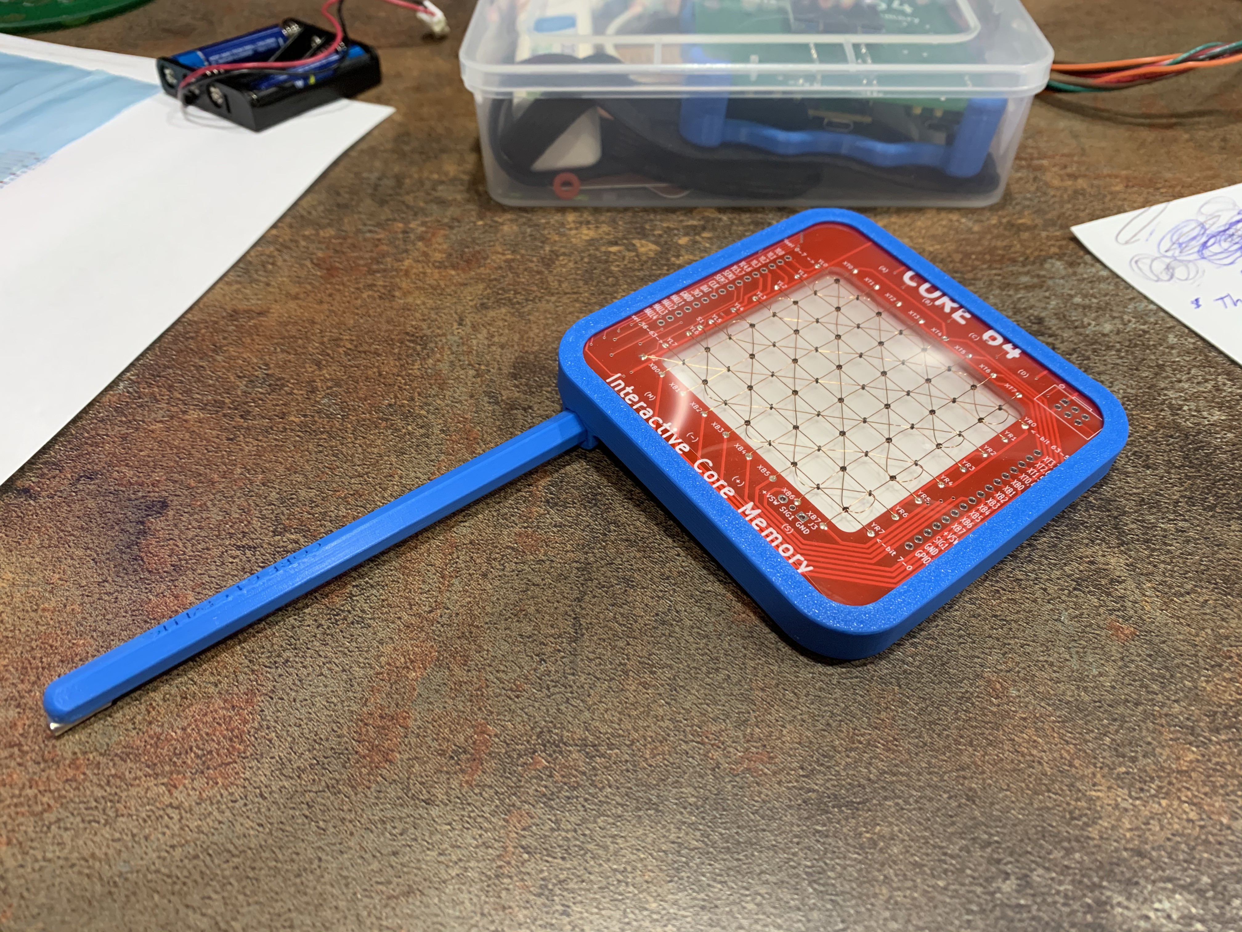
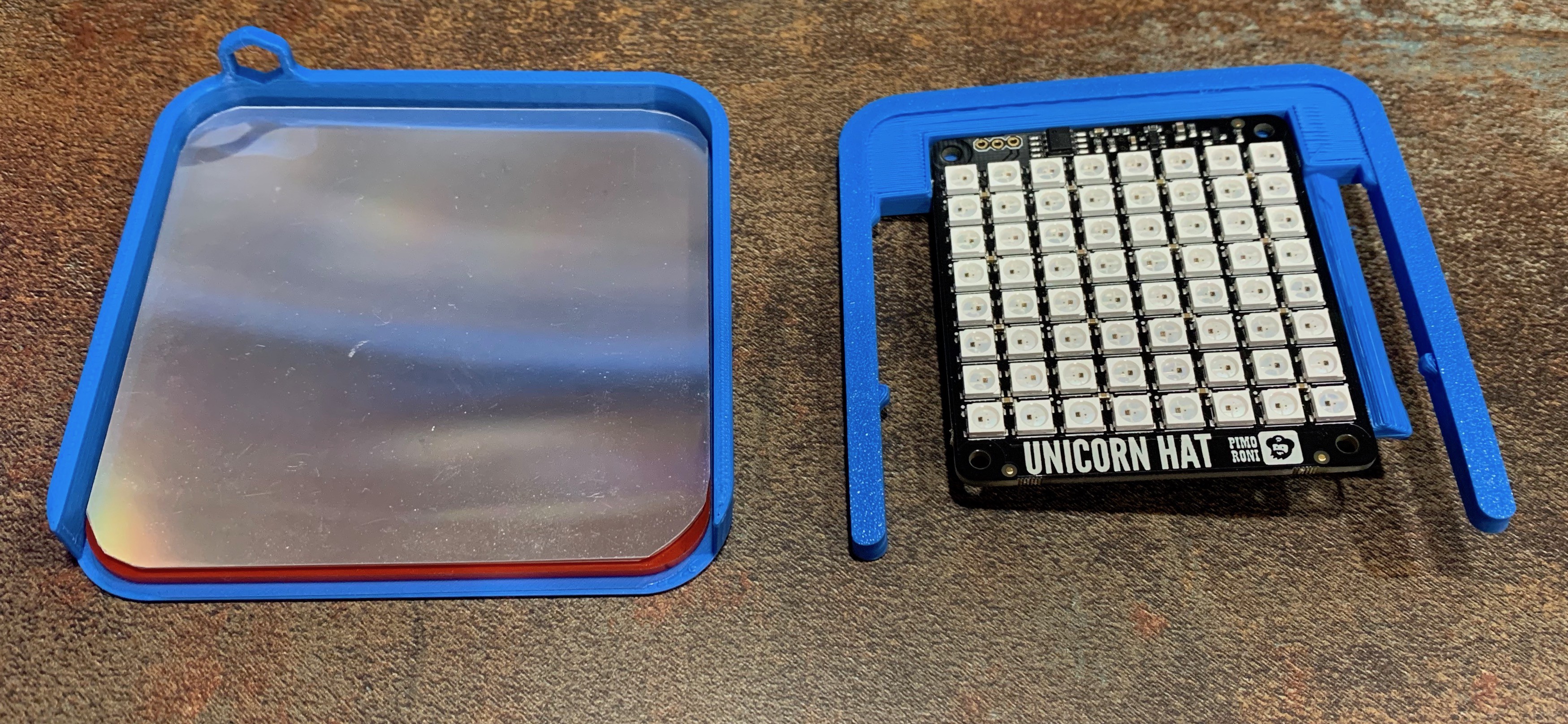
    The first prototype design of the Core+LED Array holder is now in hand, ready for testing and design refinement.

    This is the direction I'm headed for a complete assembly:

    More refinement is needed, but just going through one cycle of the design/make process has already illuminated some breakthroughs in the assembly process for the LED Array holder. Even at this stage, I'm surprised how quickly everything comes together for a professional look thanks to quality 3D prints. 

    There is a screen protector layer over the cores (transparency film) and a diffuser layer (from a scrapped LCD panel) between the LEDs and the cores. And because printing this as one part creates a lot of support material (and removal work), I diverted to a two piece design, and now I don't need as many cut-outs, so that open gap on one end of the bezel will be completely filled in. Nice discovery to figure that out after I started printing the first one.

    This project is quickly picking up steam again.

  • Beginning assembly of the Dual Board (red) prototypes

    Andy Geppert05/22/2020 at 12:33 0 comments

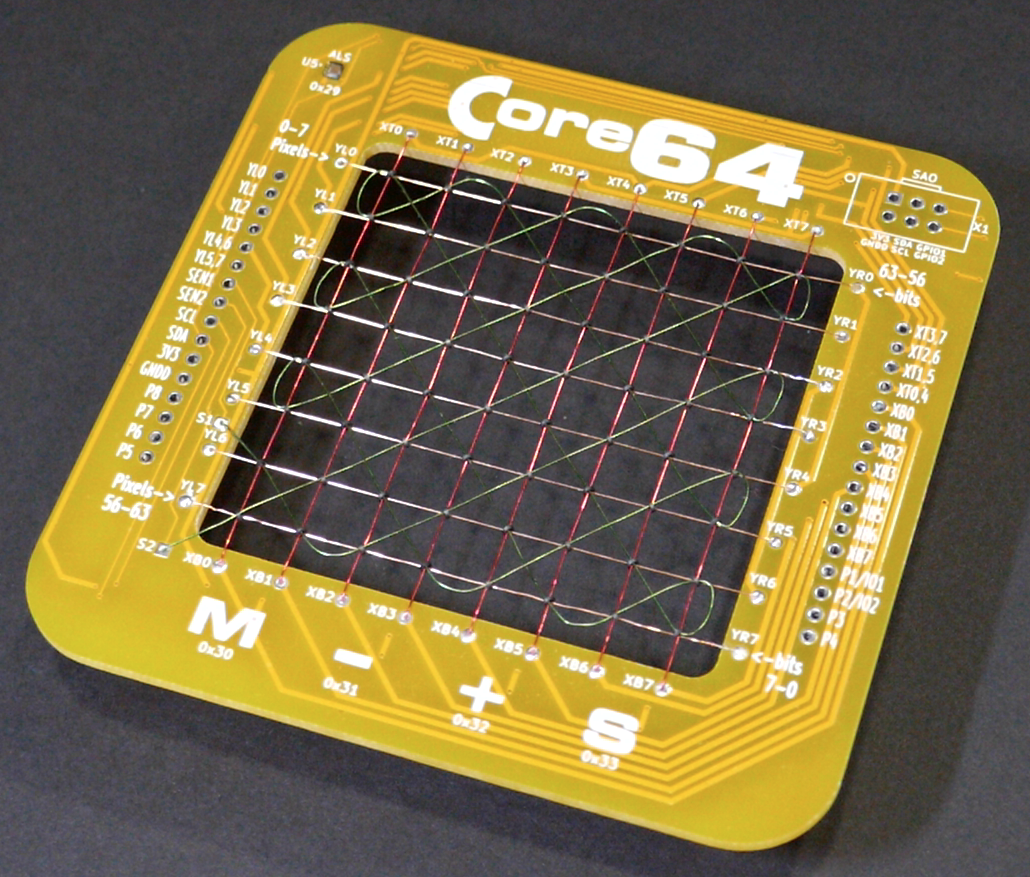
    Despite a lack of log updates, I have been making a lot of progress toward the next round of prototypes. I have moved to a dual board design which presents the core array on its own circuit board. The decision incurred a lot of work in creating two new PCBs with proper interconnections. Regardless, I'm happy with the results so far. This time the core weaving went much faster, and the results are more consistent.

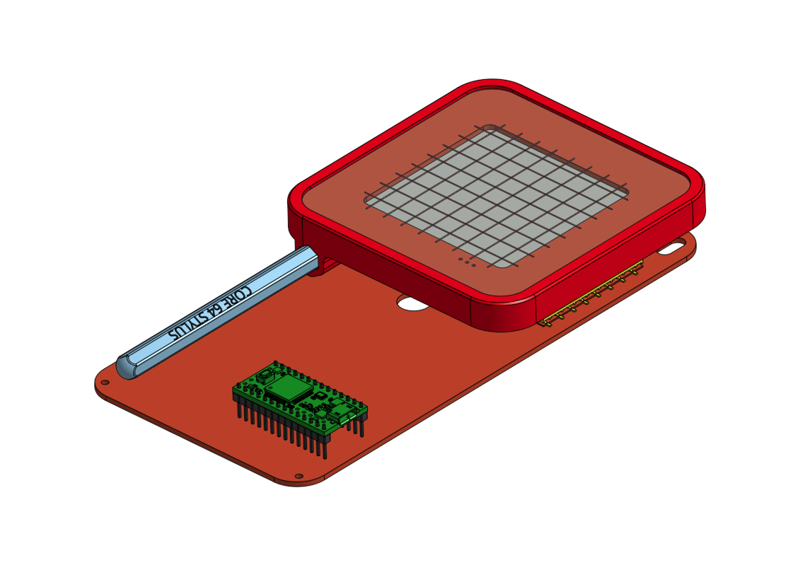
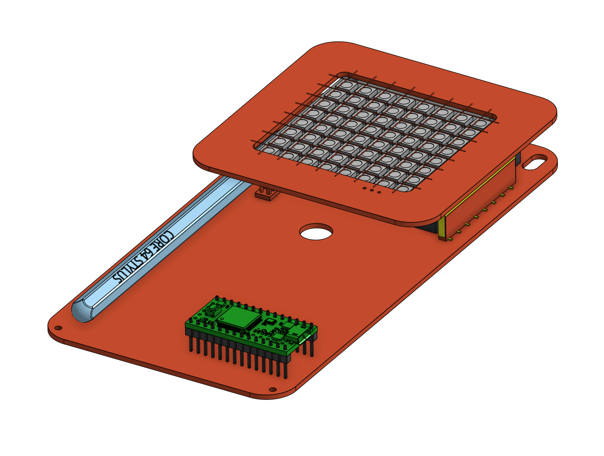
    The second board is twice as tall, and will support all of the logic functions. The core board will plug into the top of the logic board, like this:

    I'm looking forward to receiving the logic board in the next 3 days. In the meantime, I aim to complete the assembly of the core board and complete some basic tests.

    The benefits of this revised approach are:

    1. A more physically robust design that does not require a supporting enclosure on the back side. It also sits flat/stable on a table surface.
    2. All of the components on the logic board are on the top which makes troubleshooting much easier.
    3. The core board can be sold separately with a much lower cost so potential buyers can make a minimal investment to see if they want to follow through with the complete project before committing to the more expensive logic board.
    4. It is easier to assemble the smaller core board on its own.
    5. The sandwiched design hides the battery pack between the boards, and provides an area to secure the stylus (with 3D printed balogna between the boards).

    Here's to prompt shipping by FEDEX for the Digi-Key.com components, and to DHL for the logic boards from JLCPCB.com. It'd be great to receive them this weekend, please!

View all 25 project logs

Enjoy this project?

Share

Discussions

Jibril wrote 03/02/2020 at 15:30 point

Your welcome!!

  Are you sure? yes | no

morgan wrote 02/29/2020 at 06:20 point

Look forward to seeing the 0xDEADBEEF (or 0xC0D3C4FE) readout

  Are you sure? yes | no

Andy Geppert wrote 03/01/2020 at 05:15 point

Working on it... 64 bits is just enough room for both of those hex values. I thought it would be easy, but Arduino/GCC 32-bit-land appears to get weird with some bitwise operators greater than 32 bits... And with serial print... And probably with the Adafruit OLED libraries. More "unexpected learning" and am now trying to work around it.

GOT IT!

https://hackaday.io/project/166155-core-64-interactive-core-memory-badge/log/174384-0xdeadbeef

  Are you sure? yes | no

morgan wrote 03/01/2020 at 05:17 point

"By midnight" he says!

  Are you sure? yes | no

Jibril wrote 02/28/2020 at 01:49 point

That is soooooo cool, awesome design but it would be nice if you put a plastic casing around the edges so you can put it your pocket and walk around with it without the fear of it breaking.

  Are you sure? yes | no

Andy Geppert wrote 03/01/2020 at 20:44 point

Good feedback on the case. Thanks.

  Are you sure? yes | no

awenisko wrote 01/31/2020 at 15:26 point

Omg, this is amazing. Kudos for your brilliant idea and design!

  Are you sure? yes | no

Similar Projects

Does this project spark your interest?

Become a member to follow this project and never miss any updates