Andy Geppert
-
Weaving core memory
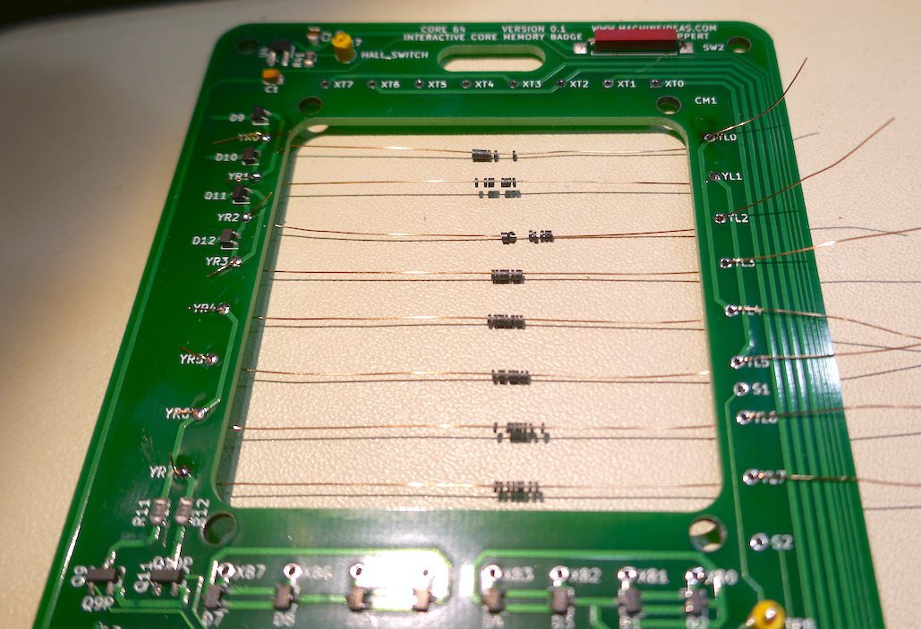
08/17/2019 at 03:20 • 0 commentsAll of the components are populated now, and the accessory functions are in place. The focus tonight was the weaving part of the project. This part of the process makes the SMT work seem easy.
![]()
The rows are installed, and the technique I have right now makes each row take about 10 minutes. Having started the columns now, I don't think I should have tightened the rows until the end. I have three columns threaded and those are about 20 minutes each. The weaving process is looking like a 3-4 hour job in the first pass. I'd like to see a nice square grid, but that aspiration may be a little two grand. This part of the proceed needs some refined techniques which I have yet to develop.
-
PCB Bring-up has begun!
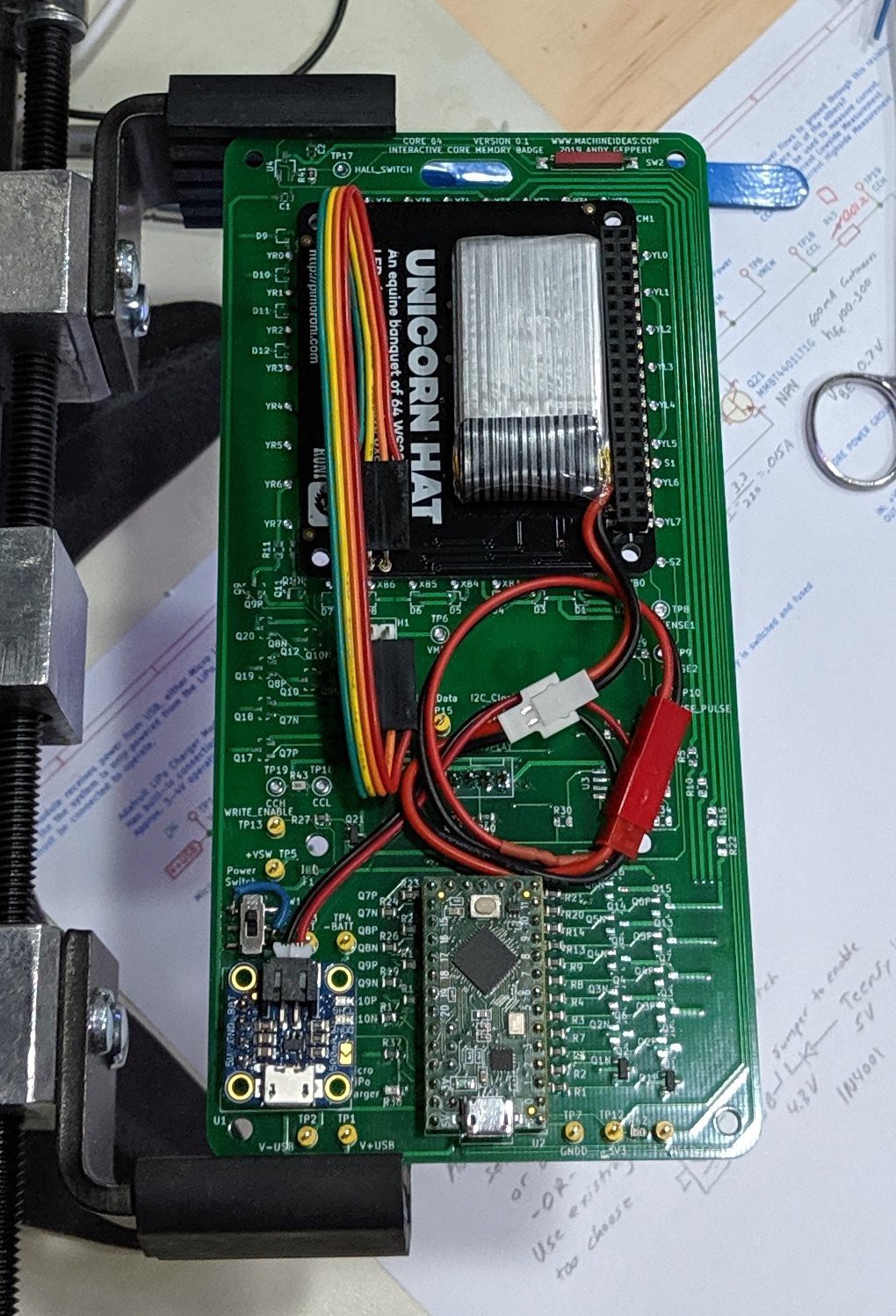
08/15/2019 at 14:11 • 0 commentsThe bare boards just arrived, right on schedule! The first step was to bring-up the board to the demo state I had tested on the breadboard. It's all working as expected with the following functionality so far:
- Power switch selects battery or USB power
- Battery charge manager
- Battery voltage sensing
- OLED Display
- LED Matrix
- Reed switch
- Teensy LC
The form factor feels about right and the next steps are:
- Bring the driver matrix to life by populating some more components
- Weave the cores
- Mount the LED Array
So far, an exciting and fast start for me. I'm very pleased with the results so far.
![]()
-
PCB Design Release for fabrication!
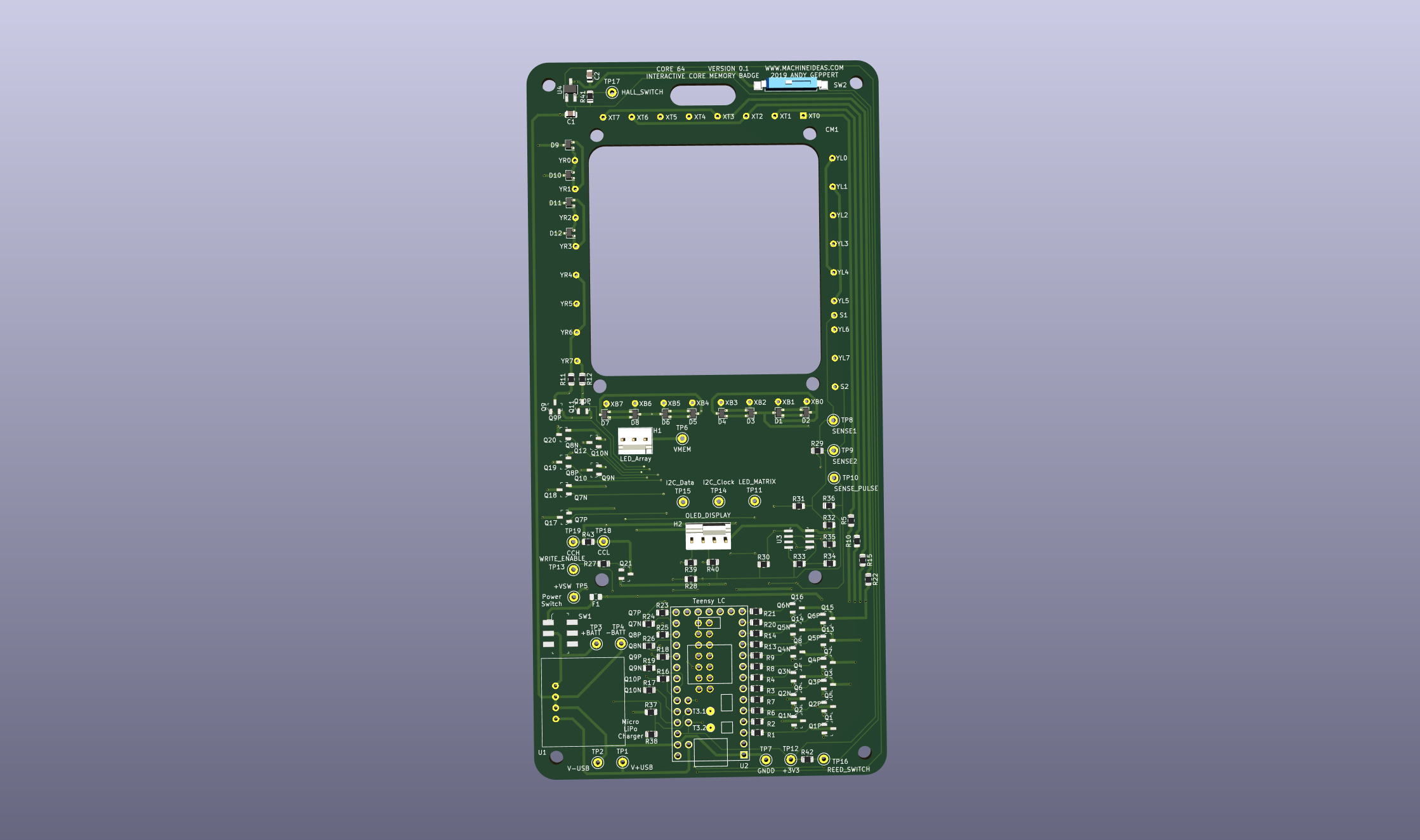
08/11/2019 at 01:33 • 0 commentsThis is my first PCB release! A major milestone and a long climb. I think I'm getting the hang of the basics in KiCad, and it's a lot of fun. Three pages of schematics, and a 3x6 inch PCB, and a few hours of learning curve...
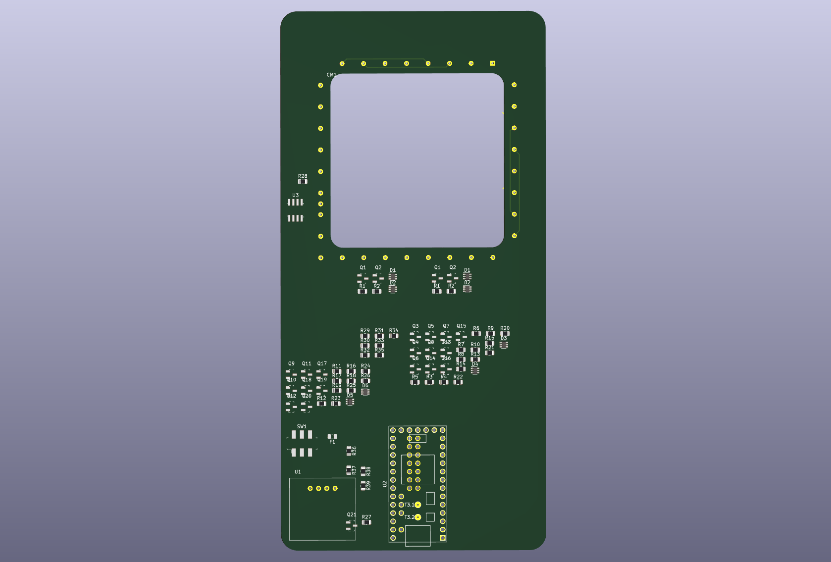
This is the V0.1 release, and I'm going for speed in the fabrication realm so it's a standard green board. Here's a rendering from KiCad, and this will be the backside of the badge:
![]()
I learned it's not possible to route traces at the corners of the board when I have the quarter-circles drawn, so I had to delete the rounded corners to in order to route and push traces around. One of the many little stumbling blocks along the way of learning KiCad I suppose!
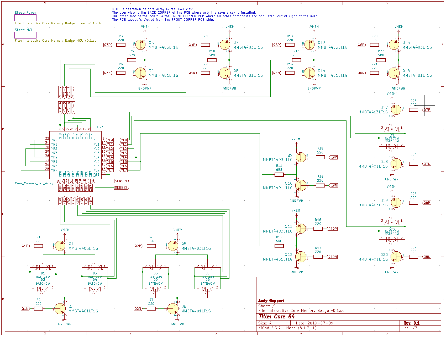
The main page of the schematic is by far the busiest. One of the project goals is that the matrix will be directly controllable in the firmware. This opens the door for the user to experiment and learn how to control the resistors directly from the code instead of pushing that decoding into other hardware. Similarly, the sensing circuit is minimal to enable flexibility via code. The primary goal of this project is to make core memory an interactive experience, but a secondary goal is to enable learning and creativity to flow from the experience of programming this contraption.
![]()
All of the components are ordered and mostly received... I took some risk on the cores and wire by ordering from eBay and I think they will come on a slow boat. I do have a handful of spare cores that should get me started for board bring-up though.
Goodies that made it into the first prototype:
- Pimoroni Unicorn Hat aka "An equine banquet of 64 WS2812B RGB LEDs in a handy, expressive 8x8 grid"
- OLED display on the front [optional]
- Adafruit Microlipo charger
- Teensy LC (just enough IO!)
- A hidden reed switch
- A hidden hall switch
The next update log should will share the excitement of bringing the PCB to life, and the creation of a list of the opportunities for improvement in the next version.
-
Schematic and PCB layout
08/01/2019 at 03:58 • 0 commentsI'm cutting my teeth in KiCad and have the schematic created and the board outline getting ready for routing. Latest state of the files are updated in GitHub.
![]()
I need to review the schematic and footprints closely before diving into the layout. I'm excited to get this fabricated though!
-
Hardware IO Testing Breadboard
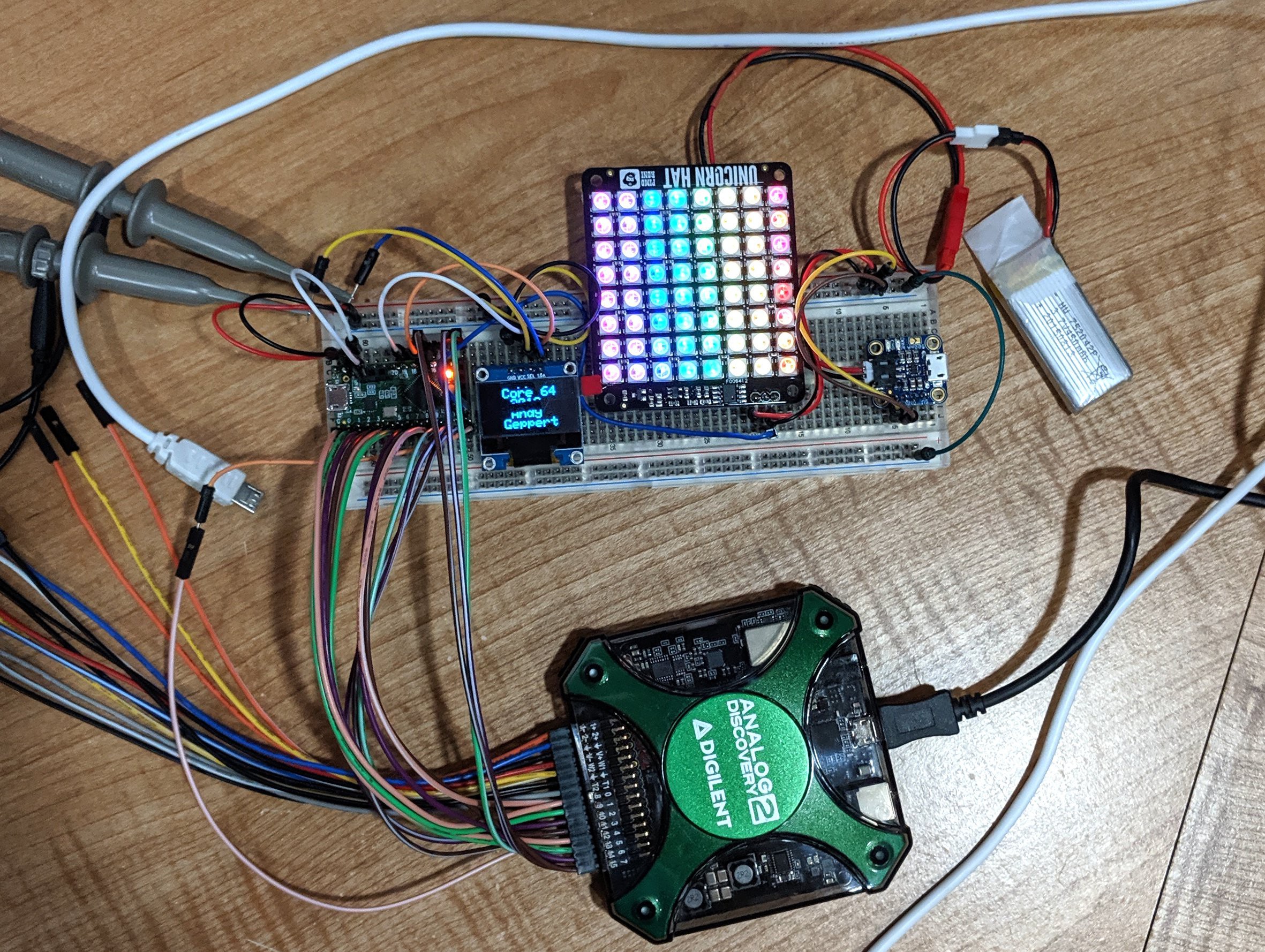
07/08/2019 at 12:22 • 0 commentsIn order to make sure I have a workable hardware solution, I'm pulling together the various components I intend to use to make sure there is enough IO and that it maps out as I think it will to the Teensy LC pins. The source code on Github has been updated to reflect the state of the project now.
![]()
The important parts of this hardware testing are:
- Will it all run from a single cell LiPo since that is the lowest voltage I intend to use? Yes.
- Since I plan to use discrete IO on the Teensy LC to directly drive the 20+ transistors needed for 64 cores, are there enough pins without conflicts? Yes, although some pins will be used for more than one function to keep a few IO pins open. The shared pins will be: I2C bus, LED Array.
- The LED Array runs well on GPIO 17 through the buffered output with a 1S LiPo. The Unicorn Hat looks like a great option to use directly, as is.
- The OLED screen is for testing the I2C bus, which I intend to use for some hall sensors and general expansion.
- As shown above, the components are drawing about 70 mA. The LED matrix brightness is set as low as it can go. The cores are not running, but the current pulse is expected to be about 300-400 mA, and will be handled with a capacitor to make sure the system doesn't brownout.
TO DO NEXT:
Connect and drive some cores through Jussi's 4x8 shield to ensure adequate power sourcing. Then get going on the circuit and PCB prototype in KiCad!
Core 64: Interactive Core Memory Badge
Weave your own Core Memory to learn and hack!