-
More current testing
11/30/2019 at 18:34 • 0 commentsI did some more testing without a load but with a beefy power supply in constant current mode (the source be the load!) now. 6.4A through the 0.05 Ohm shunt is working beautifully for extended periods of time. The shunt gets to 82degC, so some active cooling with forced air is probably on order.
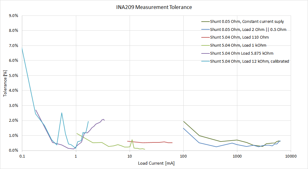
Here is a plot of test results, that show tolerances <2% across the range. Measurements below 200 uA are getting inaccurate. In general, tolerance increases at the lower end of every range, which means more noise at lower voltages across the current shunt.
More numbers and graphs to follow. And I need a different load to bridge the gap between 60 and 100 mA.
-
Read the datasheet ...
11/18/2019 at 18:00 • 0 comments... always.
During testing I noticed a significant difference between measured and expected current values. "Well hidden" in the datasheet (page 3 Electrical characteristics) is this line:
Vin- is the culprit here: Basically the part has a pull-down resistor connected to its negative measuring input pin! Really? This 'feature' draws 3.125uA typical per volt of bus voltage, which messes up low current measurements. And this is only a typical value. Every part has to be tested to find its real value.
This is one of the reasons, I decided to change the low current shunt resistor from 500 Ohm to 5 Ohm and bury my dream of measuring nA with this device.
On a side note: The widely popular INA219 has the exact same issue.
-
Current testing
09/24/2019 at 18:03 • 0 commentsThe board survived 4.95 A through the 0.05 Ohm shunt and test jig 0.5 Ohm resistor for > 1 minute. The shunt did not get too hot. My index finger temperature probe stayed rare.
The 5 W power resistor on the test jig got too warm to touch, so some forced air cooling will be required for longer tests. Or a bigger resistor to handle the 12.5 W.
Todo: Getting a log of the measured data from the INA209 and more testing to follow.
Load Measurement with 0.05 Ohm Shunt
Multimeter Verification Fluke 179
Accuracy 0.5 Ohm 4983.4 mA 5.0 A 99.7% 193.2 mA 0.194 A 99.6% 5.271 A 5.29 A 99.6% 2 Ohm 220.6 mA 222.1 mA 99.3% 400.9 mA 399.4 mA 99.6% 110 Ohm 52.4 mA 50.0 mA 95.4% 25.6 mA 25.0 mA 97.7% 9.8 mA 10.01 mA 97.9% 4.2 mA 5.01 mA 83.0% -
Test Jig 2
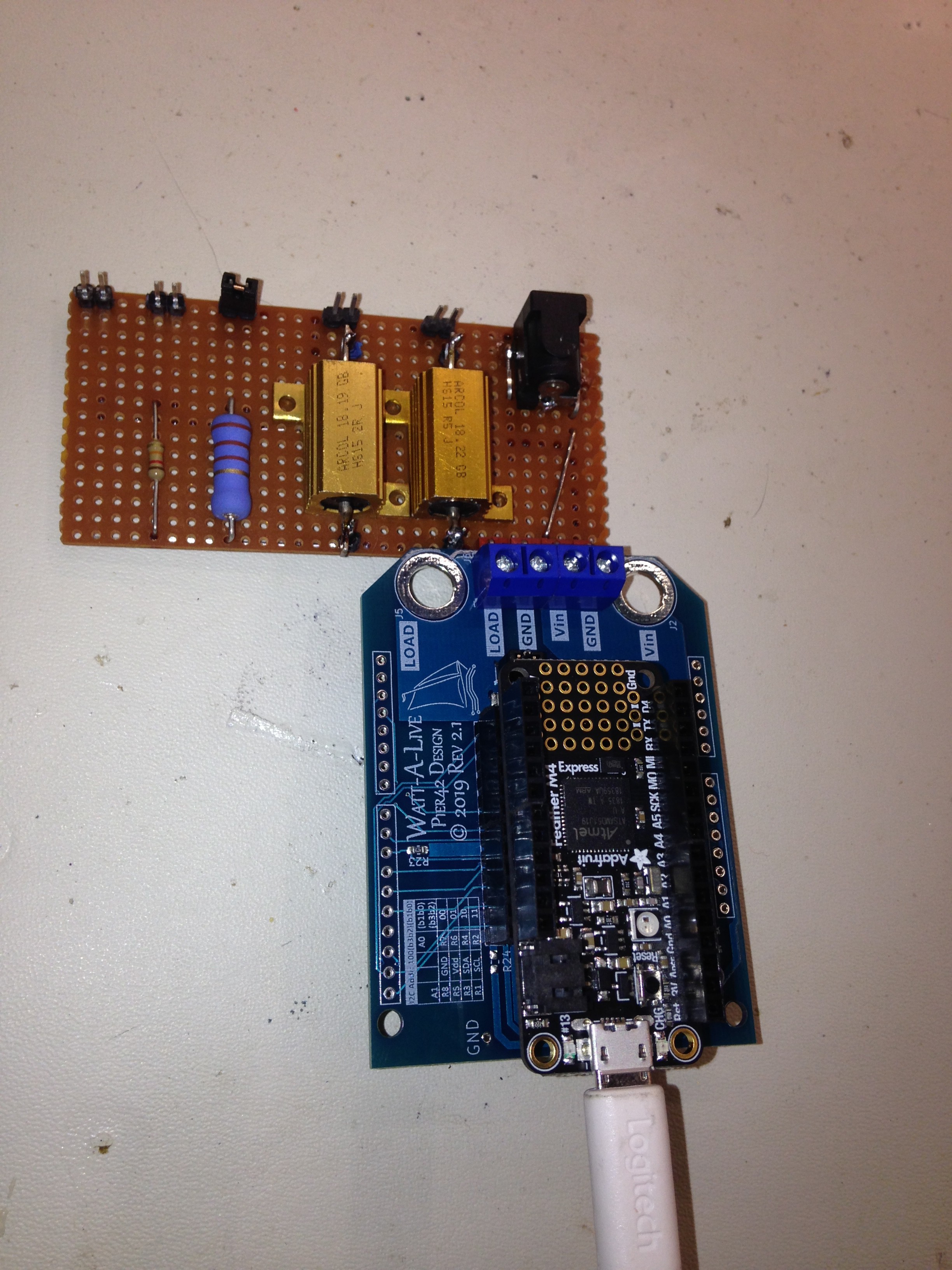
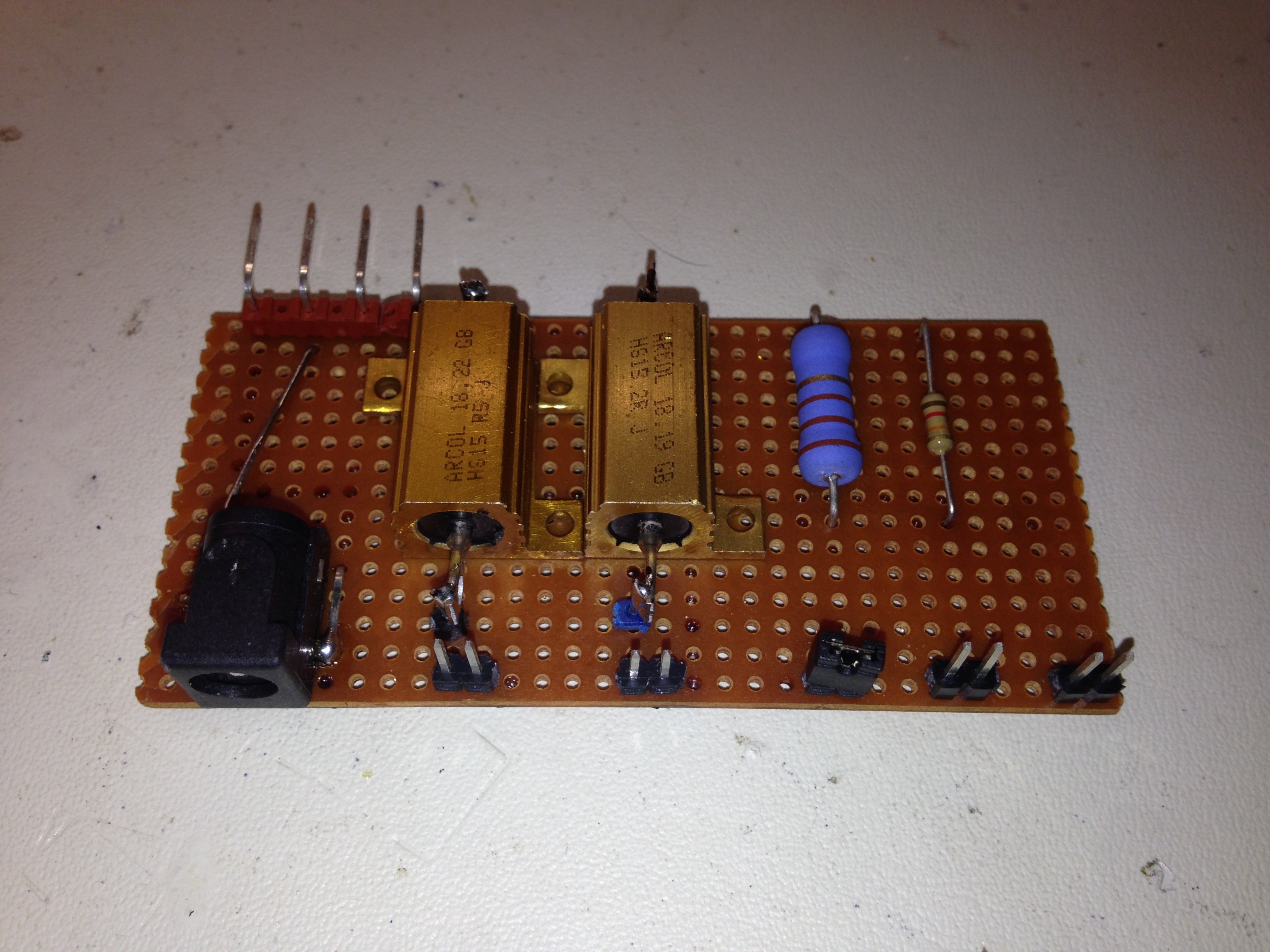
09/16/2019 at 23:52 • 0 commentsI built another test jig, this one to exercise the business end of the Watt-A-Live. It has a barrel connector to adapt to an external power supply and a selection of 5 load resistors for different current settings.
The resistor values are 0.5 Ohm, 2 Ohm, 110 Ohm, 12 kOhm and 10 MOhm (still missing :( ) for a full range of current settings. They can all be selected by jumpers.
This is how it looks, when plugged into the shield/wing. -
Rev2 boards
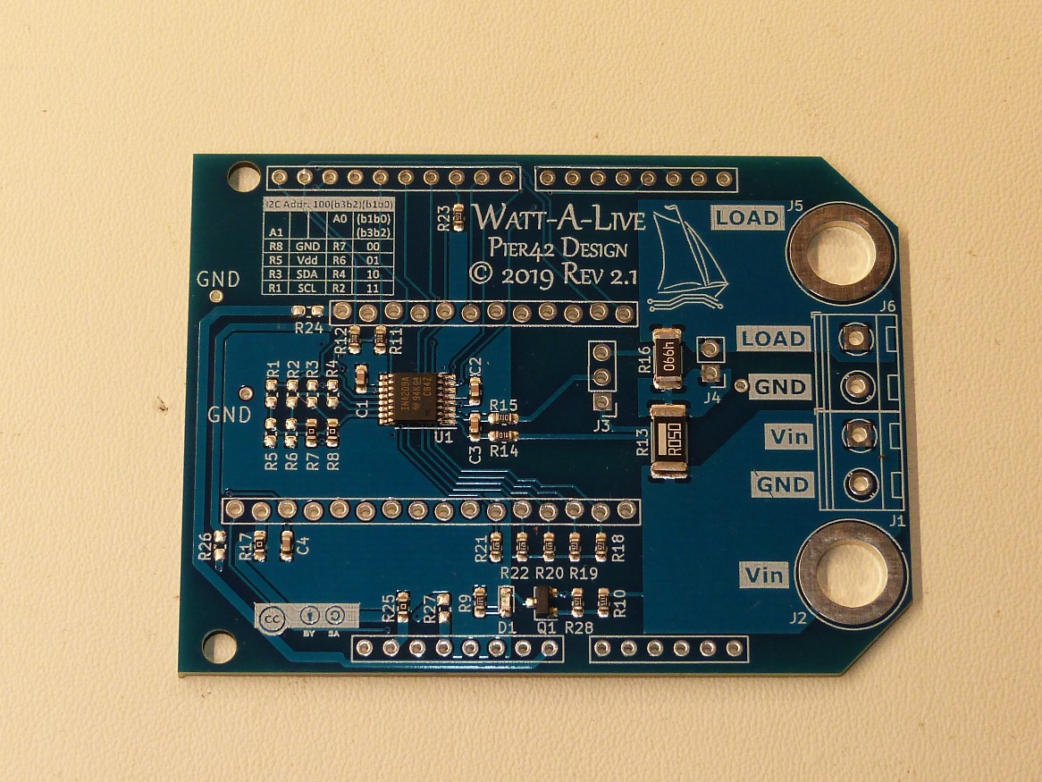
08/02/2019 at 01:51 • 0 commentsRev2 boards have arrived. They are SMD assembled by Elecrow. Quality is excellent as usual. They are labeled rev 2.1 for tracking purpose as I had to make a small change after the quote with the 2.0 data files.
Differences in a nutshell:
- Boards a longer to give access to the bypass jumper when a Feather is plugged in from the top.
- Shunt have an improve power rating.
- The high current range shunt is now 50mOhm to give a current range from 6.4A to 200uA.
- Banana jacks have a solder tab on the bottom for a lower resistance connection.
And this is how to board looks like with SMD components only:
![]()
-
Test jig
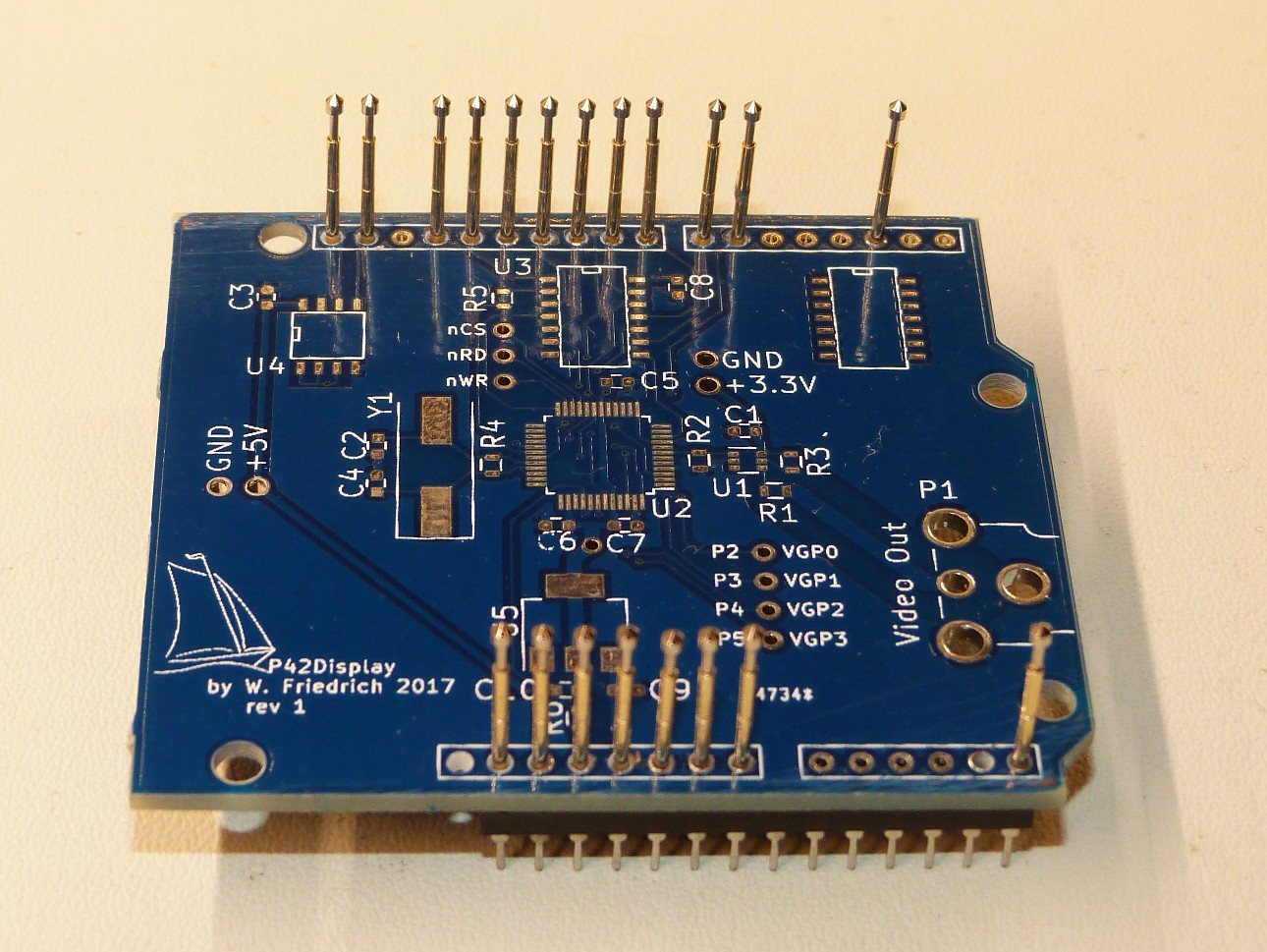
07/31/2019 at 15:39 • 0 commentsI built a test jig, which turned out to be a universal jig for Arduino Uno form factor PCBs without headers (when all pins are populated).
![]()
I ordered PCBAs with SMD components only to save cost and be able to customize for Arduino or Feather headers. To test the boards without adding connectors the jig comes into play. I used an old shield PCB and drilled out the holes to fit 1mm pogo pins. The pins soldered into IC socket rows and stuck through the PCB r proper alignment. Now I can stick the jig into an Arduino and place the shield to be tested on top and press down.
![]()
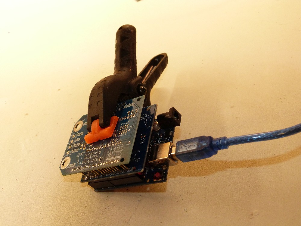
A mechanical test fixture to clamp down the board stack would be helpful, but for now it is only 25 boards to test. No really mass production yet. A crude clamp manually attached helps for longer test runs for now.
Watt-A-Live INA209 Power Monitor Shield Wing
A 6.4A-2uA current/voltage/power monitor based on the TI INA209 with dedicated GND usable as Shield, Wing, Breakout or Breadboard.
 MagicWolfi

 The resistor values are 0.5 Ohm, 2 Ohm, 110 Ohm, 12 kOhm and 10 MOhm (still missing :( ) for a full range of current settings. They can all be selected by jumpers.