Close
0%
0%

DIY Vacuum Table for CNC machines

Vacuum table for CNC machines made out of aluminium with some useful features

Similar projects worth following
In this project, we'll create a "cheap" vacuum table to hold our workpieces for our CNC machine, especially, flat material. The table should be at least suitable for milling aluminium and maybe, steel. We will add tons of features to the vacuum table as seen in commercial alternatives.

The files to recreate your own version of the vacuum table will be published here as soon as the project is finished and the table is working. When creating your own version of the table, the size of the table can be variied. I'll explain the details of the design while the project is running.

For my CNC router, I'm in need of a method to hold my workpieces. Sticky tape does work, but it is a pain to remove it after milling. Furthermore, the presented method of NYC CNC using superglue also does work very well, but it requires lots of preparations, namely, very clean surfaces, tape has to be applied accurately to both, the workpiece and the mounting plate, glue has to be applied to the workpiece, accelerator has to be applied to the mounting plate and finally, after all that preparation, it is important to align the workpiece quickly before the glue fixes the workpiece in place.

Thus, a vacuum table is a very smart choice to fix workpieces quickly and safely to the mounting plate. There are different choices for vacuum tables, but I decided for a "breadboard" style table, since it is quicker to use. Sebastian End of END CNC has shown the easy use of a breadboard style vacuum table.

The CAD design is already close to finish while starting this project on Hackaday. We decided for a size of 450mm x 300mm, because 300mm is close to the limit of our CNC machine in one direction. The limit of the other direction is chosen like this, because we wanted to have free space beside the vacuum table, e.g. for a vice. Furthermore, we the following specs and features we would like to have in our vacuum table:

  • 450mm x 300mm x 31.5mm dimensions (height resulting of the available aluminium)
  • 10mm distance from hole to hole, so that many commercial rubber mattes will fit (e.g., the matte shown in the video of END CNC)
  • 5mm diameter of the holes, but just 0.2mm to supply the vacuum to the parts
  • Holes with M6 threads to clamp stuff onto the vacuum table
  • Three vacuum chambers
  • Possibilities to add end stops to three of the four sides
  • About 4 mm additional thickness to be used to plan the surface if required 

The current CAD model consists of two main aluminum parts, some sealing mass, pneumatic connectors and some screws. That's it. 

To use the table, some other parts are required. At least one vacuum pump, some tubes, mattes with 5mm holes (10 x 10 raster) and some mattes to close the remaining holes of the table.

There is a video series on Youtube where the parts are machined and assembled. The videos are linked below.


Hackaday Vacuum Table v2.stp

Version 2 of the CAD model. Changes: - Depth of pockets in bottom plate reduced - Added small pockets for pneumatic connectors

stp - 7.43 MB - 08/09/2019 at 18:25

Download

Hackaday Vacuum Table.stp

Initial version of the CAD model

stp - 7.38 MB - 07/03/2019 at 19:24

Download

  • 1 × Sheet of aluminium for base plate 460mm x 310mm (at least 20mm thick)
  • 1 × Sheet of aluminium for top plate 460mm x 310mm (at least 9mm thick)
  • 3 × G 1/8" to 12mm pneumatic connectors Teflon tape should be used, 12mm can be exchanged to your needs
  • 20 × M5 x 12mm screw DIN 6912 Low Head Socket Cap Screw Grade 8.8
  • 1 × Sealing mass

  • Assembly, final holes and threads

    I'm a maker08/29/2019 at 19:46 0 comments

    It has been a while since the last update and video has been released.

    In this final episode of the DIY vacuum table video series the components of the table are assembled. Furthermore, some final preparations are done, e.g., cutting holes and threads for further work holding features.

    Between the top plate and the bottom plate, sealing mass is applied. Instead of this mass, a sealing cord could have been used. But to use it, a groove has to be cut in the bottom part, so that the sealing cord as a defined position and thickness.

    I'll test the vacuum table with different parts. First, some aluminium stock material is tested with my whole force to move or remove it from the vacuum table while the vacuum pumps are working. It really does work very well and it is quite impossible for me to move or remove the part from the table. Second, one of two stiffeners for my z axis is machined on the vacuum table. A quick demonstration of this is shown in the video.

    Thank you very much for your support. It has been a fun project.

  • Machining the bottom plate

    I'm a maker08/09/2019 at 20:21 0 comments

    In this week, I have milled the bottom plate. It is the first part of manufacturing steps regarding the bottom plate. Have fun watching the video.

    At the sides the holes with different threads are missing yet. One side should contain three holes with a 1/8" British Standard Whitworth thread for the pneumatic connectors. The other three sides should contain several holes with M5 threads to add end stops as shown in one picture in the project gallery.

    In the next video of this series, the holes at the sides are drilled and the threads are cut. It is some manual labour. To get the holes perpendicular to the surfaces, a little helper is machined. More on that in the next days.

  • Updated CAD model

    I'm a maker08/09/2019 at 18:46 0 comments

    Before machining the bottom plate, I updated the CAD model. In the new model the pockets are not that deep as in the initial version of the model.

    Why did I change that? Well, there are several reasons. 

    1. More weight of the vacuum table. Weight is good for CNC milling machines, but of course, it is not so good for the machinist ;-)
    2. Reduced milling time. But for me, it doesn't really matter.
    3. Less waste to clean up

    In addition to these changes, there are some deep pockets close to the pneumatic connectors, since they are about 10mm thick.

  • Photos of top plate

    I'm a maker08/09/2019 at 18:13 0 comments

    After finishing the top plate, I missed showing some pictures. So, here they are...

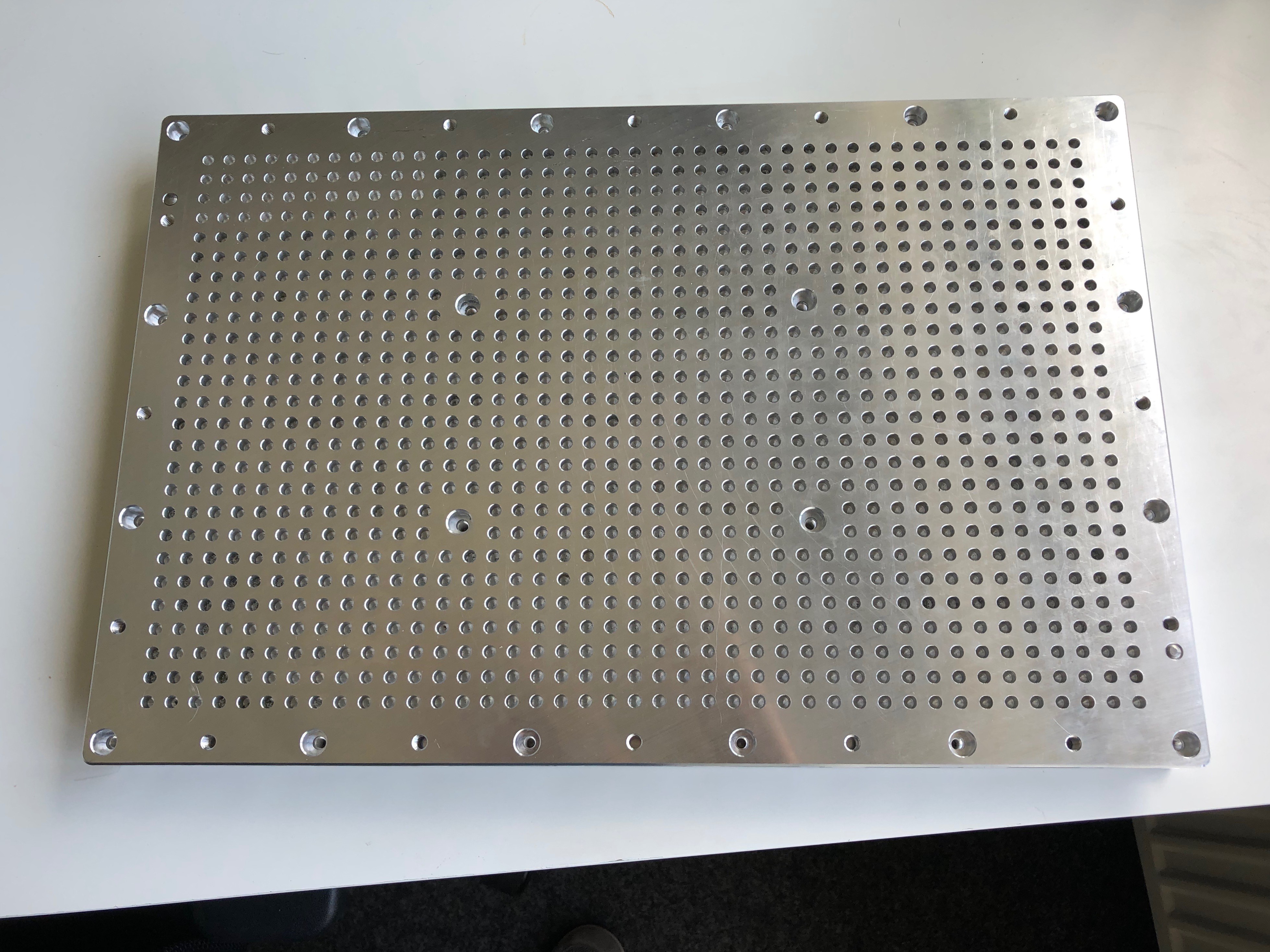
    The first picture shows an overview of the plate. On the top left, the holes are already cleaned up.

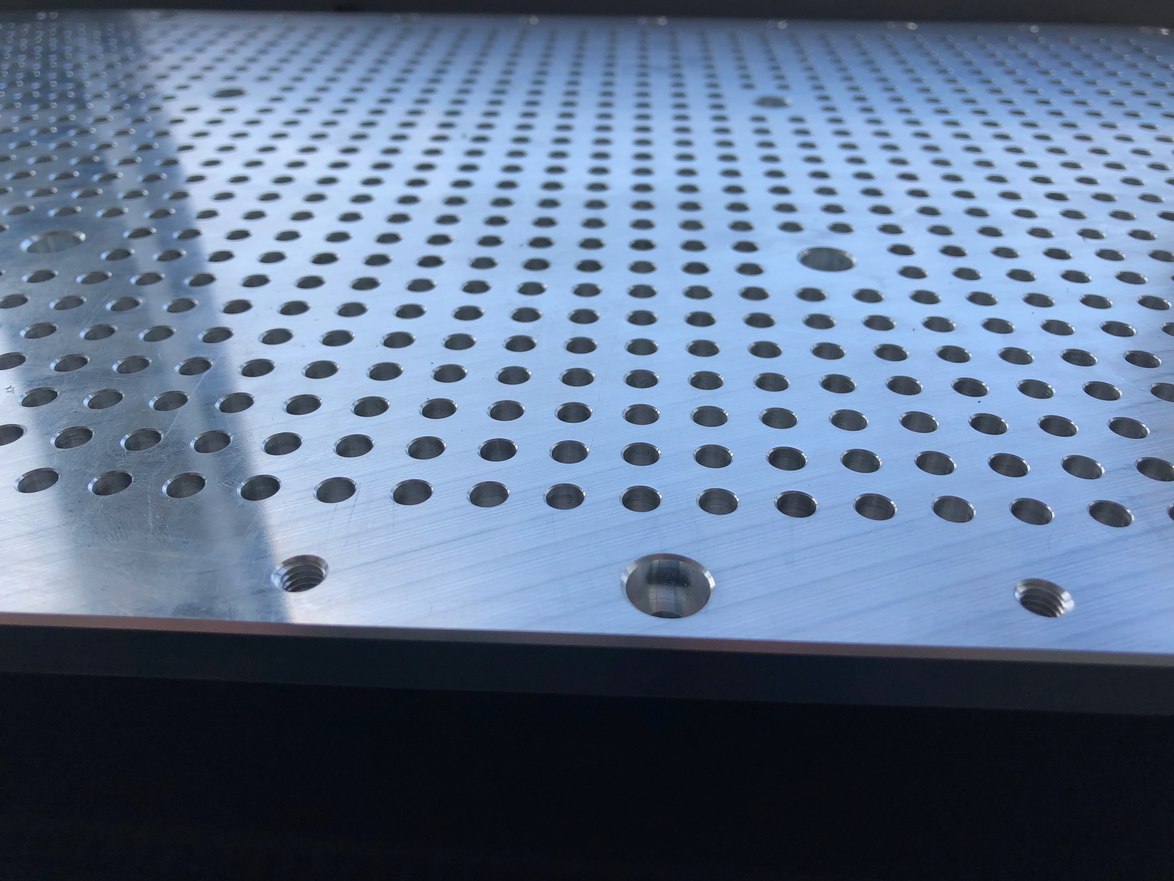
    The second picture shows a side view with nice chamfers.

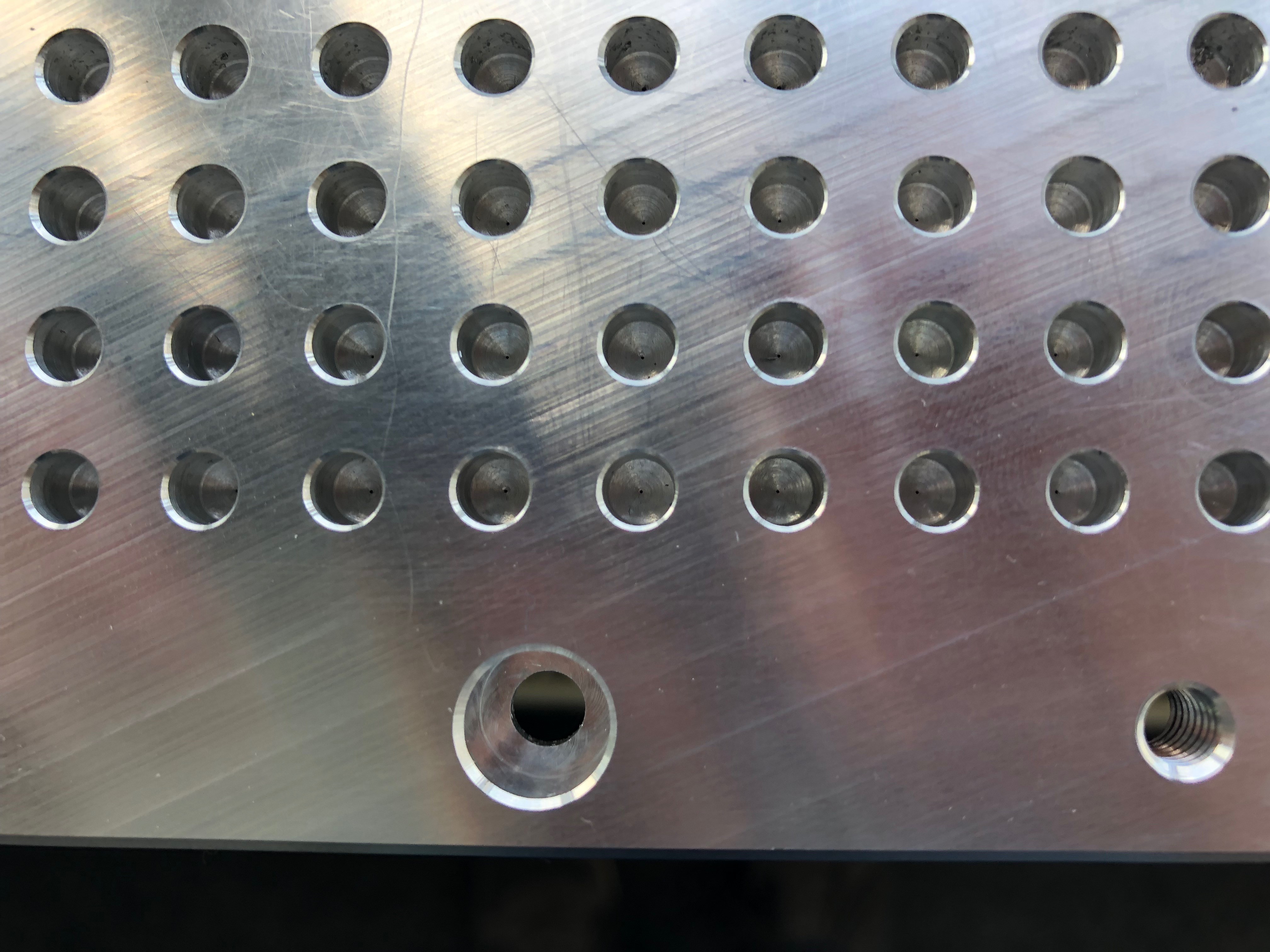
    The last picture shows a close up of the vacuum holes. There are the small holes (0.2mm or 0.3mm) inside the 5mm holes.

  • Finishing the top plate

    I'm a maker08/03/2019 at 18:36 0 comments

    As announced before, the next video of the machining is available. There, you see some drilling, chamfering and cutting of threads.

    Drilling these small holes really f***ed me up. At the beginning I used cheap 0.214mm drills, until all of them had been broken. Thereafter, I bought not so cheap 0.2mm drills, which also broke. Finally, the 0.3mm drills worked. I could drill them all with the 4 drills, I had available. Now they are also broken. Thus, when drilling these small holes, it really depends on the speeds and feeds for the drills you use. For the latter ones, a guy I know from facebook sent me the drills for free. Furthermore, he supplied me with correct speeds and feeds. Or at least, the speeds and feeds he had been successful drilling holes. So, at this point, thank you very much for the drills and your knowledge!

    After drilling the small holes, the remaining stuff was quite simple. Cutting the M6 threads into the holes that can be used for further clamping of work pieces had been done with a whirling thread cutter. Chamfering the outer boundary, and all the holes, a 8mm 45° chamfer mill had been used.. The vacuum holes had been chamfered just a little bit since the diameter should be about 5mm.

    A few days ago I tested the 5mm holes with some dowel pins. They can be used to align work pieces. I was really surprised how precise the 5mm holes had been drilled. The dowel pins just have a very slight amount of play, so that it isn't too hard to remove them after aligning.

    At the end of this project log I want to announce some good news. The bottom plate had been milled successfully. A video showing the machining process will be published in a few days or maybe at the end of next week.

  • More information and schedule of next video

    I'm a maker07/28/2019 at 16:48 0 comments

    Since I'm asked a few times which vacuum pumps I plan to use, I want to write it down here, so that everybody interested in this project can get the answer easily. But of course, feel free to ask, if you have any questions.

    There are some possibilities to use at vacuum devices. I cannot list all of them, so I just list the both cheapest I found. 

    1. A normal vacuum cleaner can be used if a good vacuum cleaner is available. Some adapters are available online and they are quite cheap. (Here is a link, although I'm not paid by the vendor of the link: https://vacuumtables.co.uk/vacuum-table-accessories/vacuum-manifold/vacuum-cleaner-hose-adapter-for-10x8mm)
    2. I'm using pumps of Thomas (by Gardner Denver) of the 2660 series (https://www.gd-thomas.com/en/products/compressors-and-vacuum-pumps/wob-l-piston-pumps-compressors/2660-series.html). Depending on the volume flow I'll use one, two or three pumps. At least in Germany, these devices are quite cheap on ebay (about 50€ per pump).

    Since it has been pain in the a** to drill the small holes for the vacuum and it just takes a long time with very conservative speeds and feeds, it'll take until the end of the week to drill all the 1050 holes. Currently, about 40% are drilled. The total duration to drill the 1050 holes are predicted by the CAM software to be 26 hours and 50 minutes. Maybe, I could tweak the settings, but I'm afraid of breaking another drill. 

    1. The first drills I used have been very cheap (about 9 Euros for 10 drills with 0.214mm and 1mm shaft) and they broke quickly.
    2. Thereafter, I ordered 3 new drills, 0.2mm with 3mm shaft. Furthermore, I ordered a precision collet. Each drill is about 5 Euros. They also broke.
    3. Finally, a very nice guy I met at Facebook has sent me 4 drills with 0.3mm diameter and 1/8 inch shafts. The first one has drilled about 30% of all holes and is still intact. So, I'll keep my fingers cross.

    Now, about 40% of all holes are drilled. It'll take about 16 hours to drill the remaining ones. The video of part 2 of the top plate will be released by end of the week.

  • Machining of top plate

    I'm a maker07/21/2019 at 11:02 0 comments

    Before milling the top plate, I tested the 0.214mm drills on some aluminium parts and there has been no problem to drill about 3mm deep, i.e., 15xD. But when it comes to drilling in the actual top plate, I couldn't get it to work. More on that later in this log entry.

    As shown in the video below, the first cuts on the aluminium for the top plate have been done. The outer contour, the 5mm holes and the counterbores have been milled and drilled successfully.

    If you have any questions on the milling or drilling, just ask in the comments here or on Youtube.

    Now, to the problem with the 0.214mm drills. Although drilling the small holes worked on a test part, I had huge problems to just drill one single hole in the actual top plate. There are several possibilities, why it didn't work.

    • Runout of the drill: it seems that the drills are not straight when testing them on a very accurate surface plate. I really think that is one of the main reasons why it didn't work. Maybe, for the test cuts the drill just was good enough. The runout measured is about +/-0.05mm, which is at total about half the drill size. (I really assume, that this is the problem)
    • Speeds and feeds: more rpm required or other feeds, I tried at 18000rpm and 50mm/min. These parameters worked for the test cuts.
    • Stick out: since the holes in the top plate start at about 8mm depth, the stick out of the drill has to be about 10mm. It may be a few mm longer than before when drilling in the test material.
    • Other material: the material of the top plate differs from the materials of the test cut.

    What I can definitely exclude from the reasons of failure:

    • Spindle runout: the runout is <0.01mm, so it is very unlikely that this is the problem.
    • Stability of the mill.
    • Programming errors: the drill isn't moved quickly into the material or something.

  • Material arrived, test cuts

    I'm a maker07/19/2019 at 20:18 0 comments

    Last week the material arrived. A few days ago, I sawed the aluminium sheets into correct pieces. Every piece is about 10mm larger in x and y.

    As said before, the main problem will be the 0.2mm holes that should be created. Thus, I ordered 10 drills with 0.214mm diameter a few weeks ago with 1mm shafts. I used one to do some test cuts, i.e., drilling 3 holes each 3mm deep (15xD). And surprisingly, it just worked. The holes had been drilled by the mill without a problem.

    Ok, so with the successful test cuts, I prepared the sacrifice plate.

  • CAD model uploaded

    I'm a maker07/03/2019 at 19:23 0 comments

    We've uploaded the current version of the CAD model. Some minor changes have been applied compared to the project images. At the current state, the table could be milled and assembled.

    If you see some problems in the CAD model, please do not hesitate to write a comment.

  • Material is ordered, last changes of the CAD model

    I'm a maker07/03/2019 at 18:32 0 comments

    Material is ordered. To make it simple milling the vacuum table while providing perfect surfaces at the top and bottom of each part, pre-milled aluminium has been ordered. And to make it a cheap vacuum table, we ordered remainders. The plates are much larger than required. On the one hand we have to cut them into pieces. On the other hand some material can be used for other projects. Just for your information, the remainders are more then double the material we need, but at about half the price.

    Furthermore, we ordered some tools (0.2mm drills), the pneumatic connectors and the sealing mass.

View all 10 project logs

  • 1
    Machining of top plate

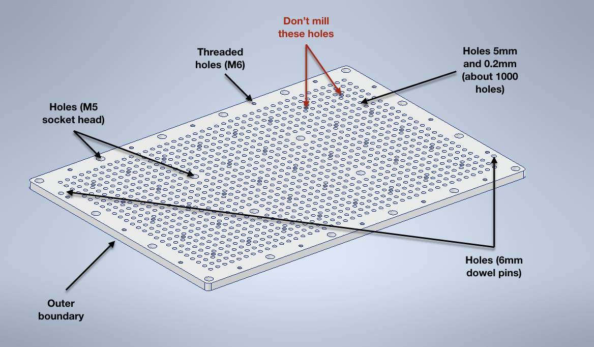
    When milling the top plate, it is important that some things of the plate are not milled in this step. So, here is a list of things you should mill in this step:

    • Border of the plate, so that you get the correct dimensions.
    • Holes for the dowel pins (holes through the plate, 6mm with tolerance m6). Since you will use a milling machine or router, try to create the holes a little bit smaller and than converge to the correct tolerance.
    • Sunk holes for M5 screws
    • First type of vacuum holes (5mm)
    • Second type of vacuum holes (0.2mm)
    • Outer thread holes (just the holes with threads at the edge of the top plate, but not the threaded holes between the vacuum holes)

    For the vacuum holes please take note of the depths and the angle of the 5mm drill. At the end, just the 0.2mm drill should drill through the plate.

    Here is a list of things you should not mill in this step:

    • Threaded holes in between the vacuum holes. They are milled after the table has been assembled and go through the top plate into the bottom plate

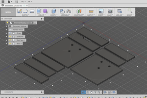
    Below a picture is shown of the top plate. The required things to mill are marked.

    Milling steps of top plate

    See part 1 of the machining and assembling series on Youtube: https://www.youtube.com/watch?v=dRxbjm6g7WI

  • 2
    Machining of the bottom plate

    When milling the bottom plate, it is important that some things of the plate are not milled in this step. So, here is a list of things you should mill in this step:

    • Border of the plate, so that you get the correct dimensions.
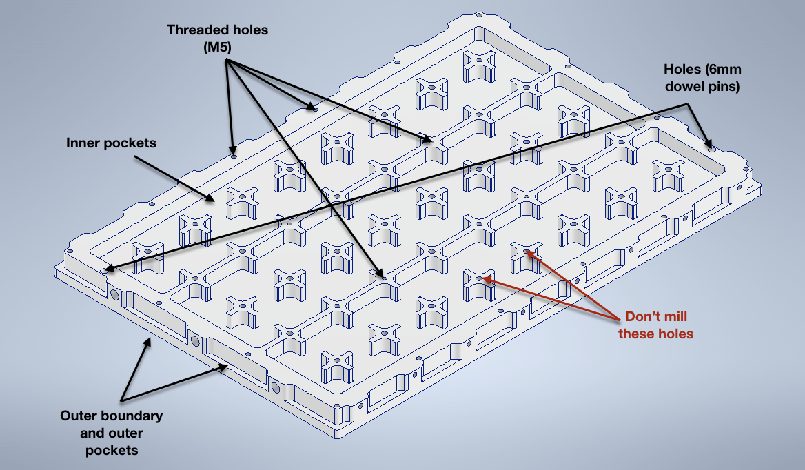
    • Outer pockets to get places to mount your vacuum plate to the work table.
    • Inner pockets
    • Holes for the dowel pins (6mm with tolerance m6). The holes should be so deep that the dowel pins stick out about 4mm, depending on the dowel pins you have available. Since you will use a milling machine or router, try to create the holes a little bit smaller and than converge to the correct tolerance.
    • Holes with M5 threads

    Here is a list of things you should not mill in this step:

    • M6 holes with threads. They are located on top of the "crosses", except 4 holes. They are milled after the table has been assembled and go through the top plate into the bottom plate

    Below a picture is shown of the top plate. The required things to mill are marked.

  • 3
    Drill holes at sides of bottom plate

    Since the dimensions are not suitable for a normal CNC router, the holes at the side has to be drilled manually. So mark and center-punch the holes, before drilling. Check the CAD file for correct positions of the holes.

    At one side you have to drill the correct holes for a G 1/8" thread, i.e., 8.8mm. 

    At the other three sides holes for M5 threads have to be drilled (4.2mm).

View all 9 instructions

Enjoy this project?

Share

Discussions

medicusdkfz wrote 07/17/2022 at 21:26 point

Thank you for this great project. Today I started with the bottom plate (900x700x20mm). I‘m using M6-steel inserts for future fixing and changed your design for my needs. I‘m also from Germany…

  Are you sure? yes | no

John wrote 02/17/2021 at 15:34 point

Have you thought about powering this with air. I saw a company that has a air powered Vacuum table for cnc machines. 

I use coolant and think this would be a good idea. I am thinking of building your table and making it air powered.

  Are you sure? yes | no

paulvdh wrote 10/23/2020 at 18:48 point

You've clearly put a lot of effort in this, but still, the design of this vacuum table is not very good.

First, with all the drilling going on, you want to put more effort in optimizing a drill cycle. Using so many short retract cycles for a not so deep hole cost a lot of machine time, and also adds wear to the drill.

You do not want to drill the big holes with a 118 degree funnel at the end. Any chips will get directed to the 0.2mm hole and it will be blocked often.

It looks like you've glued the table together, so maintenance and cleaning of the inside is difficult. Adding in an O-ring or similar is a much better solution.

Clogging and difficult maintenance is a problem with many of the vacuum table designs.

If you want to add air friction, a better way is to add tubes in the holes. For example, thin stainless tubes are very common to make injection needles. You can easily drill a 1mm hole through the top, then a hole with the diameter of the outside diameter of the tube until 1mm above the bottom of the top plate, and then insert pieces of the tubes with a length enough to keep them above the bottom of the hole.  Chips will then fall to the bottom of the hole where they do not clog the hole in the tube, and can be cleaned with a vacuum cleaner when needed.
An even better solution is probably to add some foam filters in the 5mm mm holes to fill them up completely so the top of the table is flat. If these filters get clogged, the can be removed by sticking an awl in them, or with compressed air from the backside.

I really do like your router though.
Did you buy it or made it yourself?

  Are you sure? yes | no

Similar Projects

Does this project spark your interest?

Become a member to follow this project and never miss any updates