Close
0%
0%

URU Key

URU Key - a biometric FIDO2 Authenticator
built with ESP32 / ATECC508A / FPC1020

Similar projects worth following
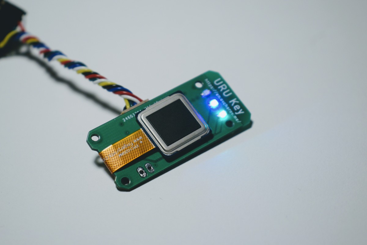
I am making a WebAuthN authenticator device using ESP32 PICO D4. The device will feature BLE connection, ATECC508a security chip and biometric authentication.

Earlier this year the new standard of secure passwordless authentication was submitted to W3C. Major browser are already in the process of implementing this standard so we can expect that this kind of authentication will be available to the end users very soon. Meanwhile I was playing with the ESP32 development board which features Bluetooth Low Energy connectivity. I think it will be extremely interesting to build personal authenticator device.

  • 1 × ESP32 Pico D4
  • 1 × IRLML2502 Discrete Semiconductors / Power Transistors and MOSFETs
  • 1 × ATECC508a Security IC
  • 1 × FPC1020AM or FPC1020AP Fingerprint scanner module
  • 4 × LED Fiber Optics / Emitters

View all 9 components

  • The new form factor for the URU Key FIDO2 Authenticator

    Andrey Ovcharov11/09/2020 at 14:39 0 comments

    While working on the side project URU Card - the open-source authenticator device in the form-factor of a regular credit card - I have noticed that it is way more suitable for daily use. The device like this can be carried around simply in the wallet together with other credit cards.

    No alt text provided for this image

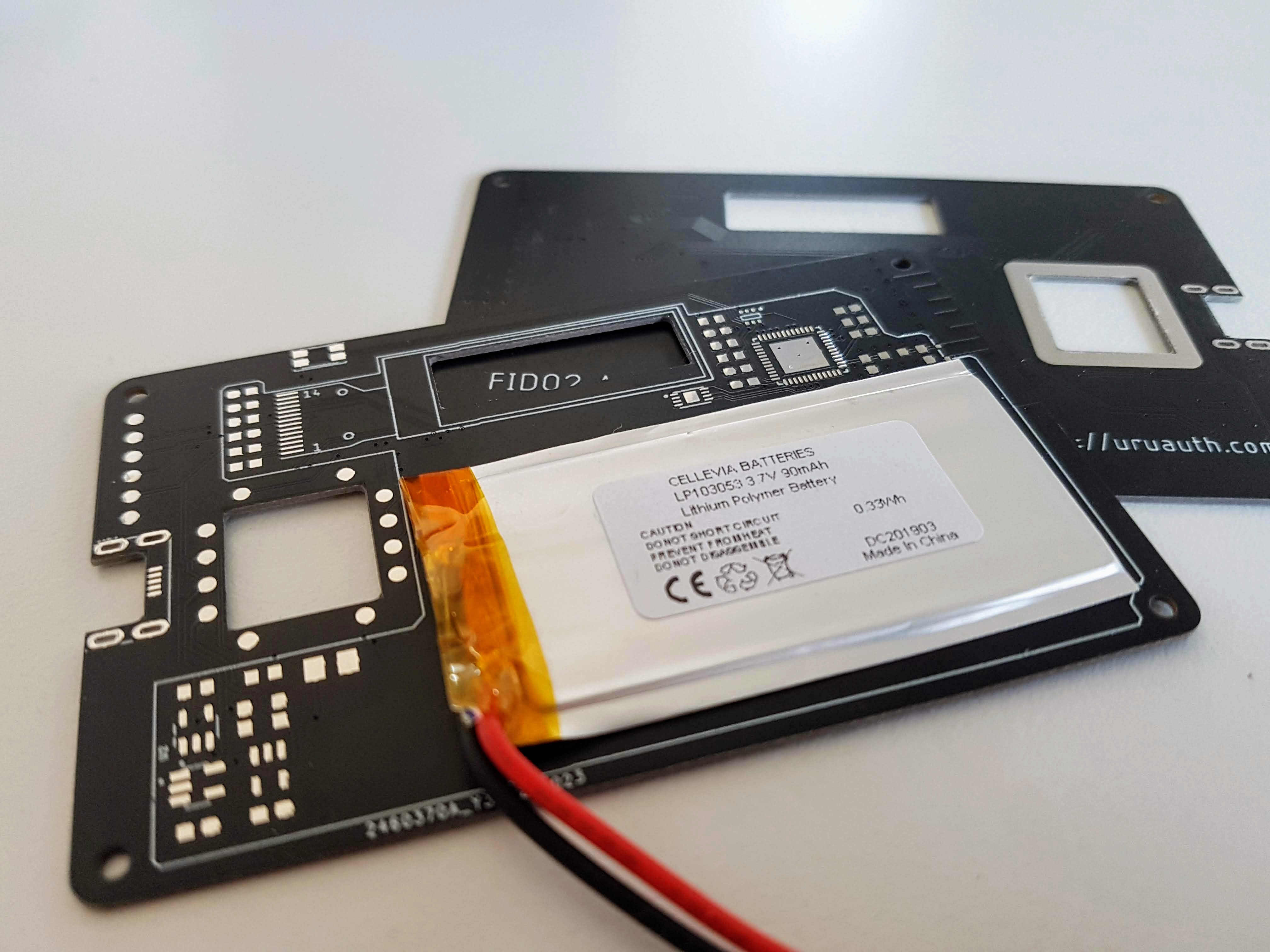
    So, I have redesigned the device in this format. The biggest challenge I had was the power source. Luckily I could discover the ultra-thin lithium battery powerful enough, and it fits perfectly in the space between the logic board ad back cover.

    No alt text provided for this image
    No alt text provided for this image

    One more addition to the user experience - a tiny OLED display. It is more informative than simple LEDs in the previous version of the device so I am going to keep it in the design.

    No alt text provided for this image

    Other than that, the device features the same set of core elements - ESP32 Pico D4 microcontroller, ATECC508A security element and the FPC1020 fingerprint scanner.

    No alt text provided for this image

    The test utility shows that all the elements work properly and the device is able to perform authentication tasks exactly as the previous version.

  • Designing new form-factor

    Andrey Ovcharov11/04/2020 at 09:07 0 comments

    I have tried to develop some kind of hard shell for the URU Key device but, unfortunately, I do not have relevant skills and materials. However, testing the URU Card and carrying it around on daily basis showed it's excellent versatility. The built in display definitely works better than just some LEDs and gives much more information on the device status.

    So, I have updated the design to build the URU Key in the form-factor or normal credit card as well. Main challenge here was to find the ultra thin battery capable to run the device. At last I have found one and ordered the PCBs.

    The battery is only 1 millimetre thin and can be fit inside such a small device.

    A few more parts for the device are still in transit but I already can't wait to start building it.

    Stay tuned!

  • New project

    Andrey Ovcharov06/29/2020 at 09:53 2 comments

    Many people asked me to open sources of the URU Key. It's sad, but biometrics part of the project does not allow me to do that.

    However, I can not leave these requests unattended. I have started a new project - URU Card (https://hackaday.io/project/173443-uru-card). It's an open-source FIDO2 Authenticator built with ESP32 microcontroller and programmed using Arduino Framework.

    Feel free to join the project! Unfortunately, I can not put significant effort into it as I am quite busy with other stuff and this is side projects. Nevertheless, I am pretty sure the community is able to move it forward.

    You can help the project sharing this information. Thank you!

  • URU Key - final hardware design

    Andrey Ovcharov04/06/2020 at 07:46 0 comments

    I am happy to say that I’m finally done with the hardware design of the URU Key device.

    It took a few months and number of iterations to complete it but now I have the device I wanted to have.

    The size of the PCB is only 40x15mm, it’s comparable to a regular fitness tracker.

    Main features are:

    • ESP32 Pico D4 system on a chip. Two cores, up to 240MHz, 4Mb of flash memory.
    • ATECC508A security co-processor. The complete solution for the cryptographic algorithms and key management.
    • FPC1020AP capacitive fingerprint scanner.
    • Rechargeable LiPol battery and USB Type C for charging.

    I understand that I’m not a hardware engineer and the design, probably, has a lot of mistakes. But for hobbyist, it is definitely good. It definitely solves the problem I wanted to solve - to create small wearable authenticator device with the biometric scanner and wireless connection.

    The remaining challenges have to be solved on the software side where I am a bit more experienced than in hardware. That means it will be more of a just work than research and I can say I am very optimistic about the result of the project now.

    Oh, and case. The device needs case.

  • How to measure battery level with ESP32 microcontroller

    Andrey Ovcharov03/01/2020 at 22:03 0 comments

    Autonomous devices like URU Key require periodic measurement of the battery voltage. I am going to use very simple schematics and very simple algorithm to understand how much juice my battery has at the moment.

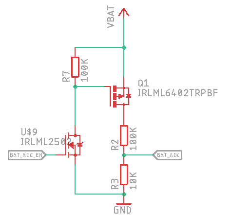
    There is a great thread about measurement circuitry and a switchable voltage divider on StackOverflow. Following the thread I have created the following circuitry for the battery measurement:

    Schematics of battery level measurement

    The positive battery terminal is connected to the line VBAT, the ADC of ESP32 is connected to the BAT_ADC line and the line BAT_ADC_EN is used to enable and disable the measurement circuitry.

    Let’s write the code which reads the value from ADC and converts it to the battery level in the range from 0 to 100%.

    In my device I have used resistors of 100K and 10K, the ones I have at the moment:

    #define R2 100
    #define R3 10
    

    The output voltage of the resistor divider is calculated as Vout = (Vin * R3) / (R2 + R3).

    #define VOLTAGE_OUT(Vin) ((Vin * R3) / (R2 + R3))
    

    As a very rough estimation, we can take the battery voltage of 4.2V as 100% and the voltage of 3.3V as 0%. I will convert them to millivolts to avoid floating-point calculations.

    #define VOLTAGE_MAX 4200 #define VOLTAGE_MIN 3300
    

    The reference voltage of ESP32 ADC is 1100mV. Let’s define it:

    #define ADC_REFERENCE 1100
    

    The value returned from ADC working in 12-bit mode will be in range 0 to 4095. Then we can convert the voltage to ADC value using the following formula:

    #define VOLTAGE_TO_ADC(in) ((ADC_REFERENCE * (in)) / 4096)
    

    So, the minimal and maximal values of battery voltage converted by a resistor divider and returned from ADC are:

    #define BATTERY_MAX_ADC VOLTAGE_TO_ADC(VOLTAGE_OUT(VOLTAGE_MAX))
    #define BATTERY_MIN_ADC VOLTAGE_TO_ADC(VOLTAGE_OUT(VOLTAGE_MIN))
    

    Retrieving value from ADC is pretty straightforward and well described in official Espressif documentation. Let’s say we have the value from ADC in the variable called adc. Then the battery level calculation will look as follows:

    int battery percentage = 100 * (adc - BATTERY_MIN_ADC) / (BATTERY_MAX_ADC - BATTERY_MIN_ADC);
    
    if(battery_percentage < 0) battery_percentage = 0;
    if(battery_percentage > 100) battery_percentage = 100;
    

    To start measurement we have to enable a high level on the GPIO port connected to the BAT_ADC_EN line. Then the current battery level is read from ADC and converted to the percentage value. After measurement is done, the GPIO port should be set to low level to avoid battery drain through the divider.

    The URU Key device does not have any means to display the battery level except three LEDs. I am going to use an effect like blinking on red one to indicate that battery level is near to critical. As well the BLE protocol defines special endpoint to return current battery level percentage. I am implementing it as well.

  • URU Key - making decision on power source

    Andrey Ovcharov02/18/2020 at 08:21 0 comments

    The next important step of making autonomous FIDO2 Authenticator device is the power source. In general, I have two options - replaceable or rechargeable batteries.

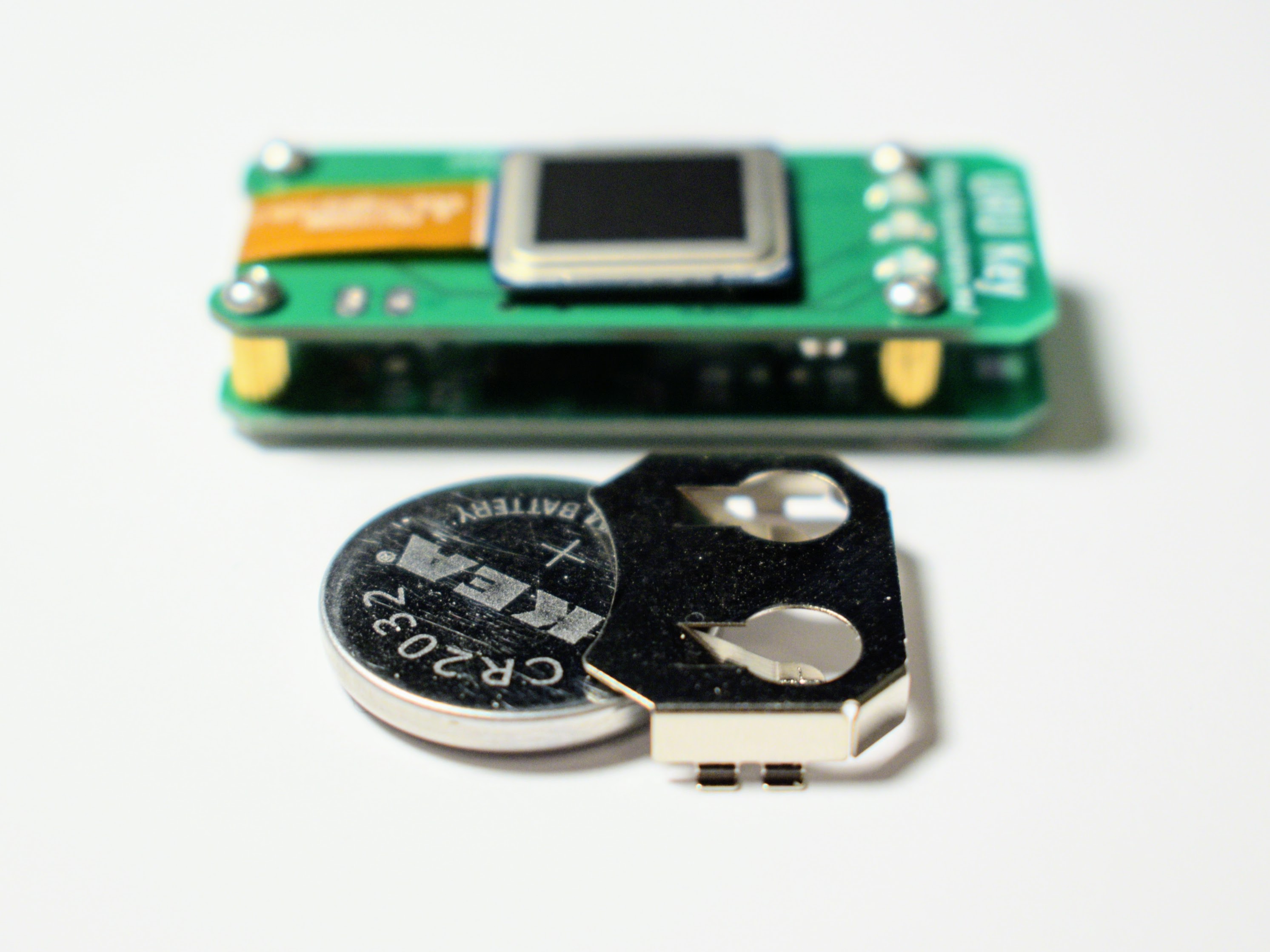
    The replaceable option is the cheapest and most easy to implement. While the coin size cell (CR2032) has a slightly lower voltage (3.0V vs 3.3V) it should provide enough power for the device built on ESP32 microcontroller.

    Power option - CR2032 coin cell battery
    Power option - CR2032 coin cell battery

    The biggest concern here is - what to do in the situation where I need to authenticate but the battery is already dead? Always have a spare battery? Does not look good, to be honest…

    The rechargeable option is better from this point of view. However, it’s more expensive and more complex to implement.

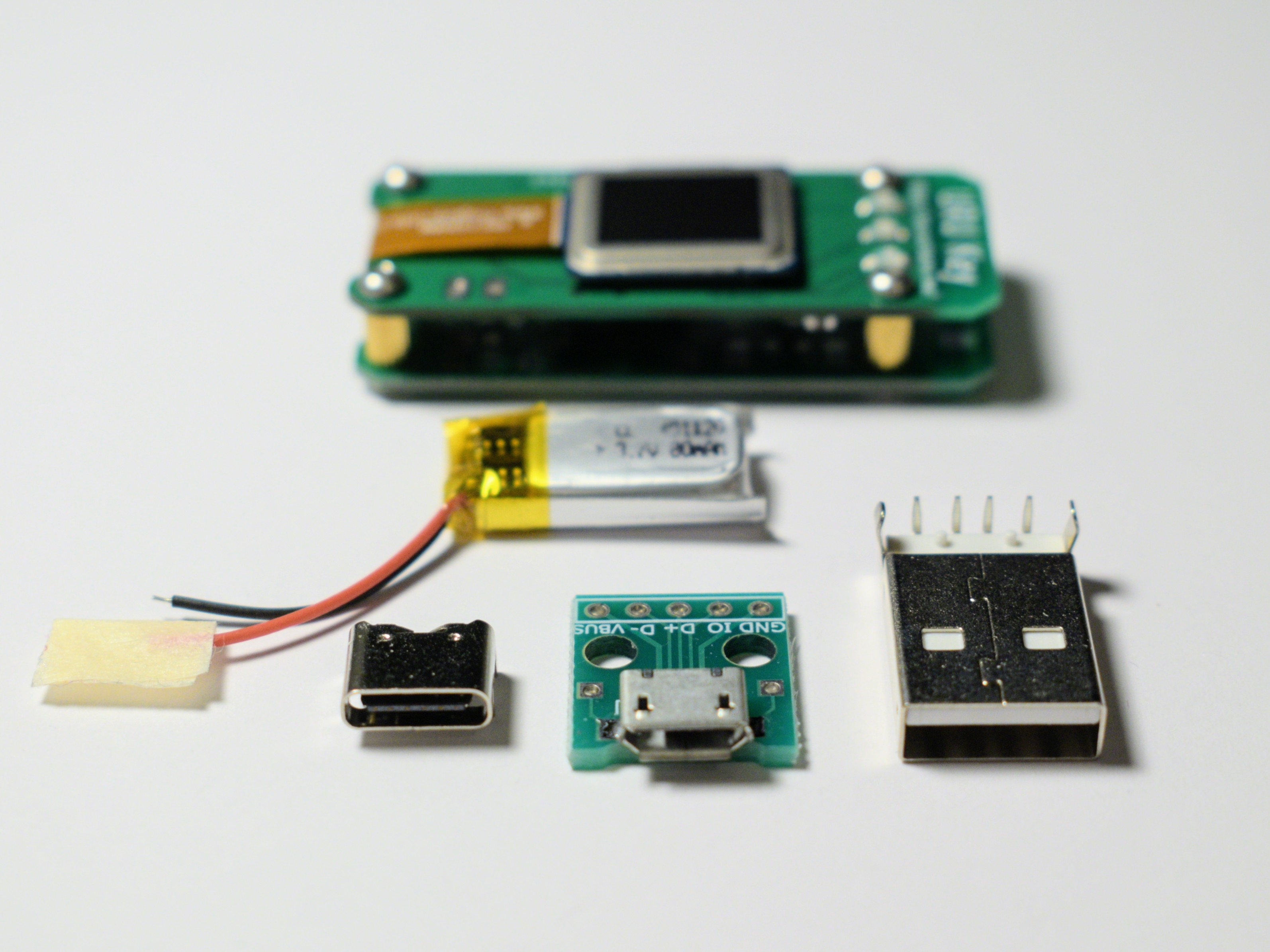
    Power option - LiPol cell battery with USB charger
    Power option - LiPol cell battery with USB charger

    Personally I think the rechargeable option is the best in my case. I have purchased the tiny LiPol cell used in hearing assistant devices and bunch of TP4054 charging ICs. They are tiny and should perfectly fit the small PCB.

    And then comes the very interesting question - which connector to use for charging? USB Type C is reversible and easy to plug in. The Micro USB connector takes the least space on the PCB. USB A can be found almost everywhere as a universal charging solution but really huge compared to others.

    Another important thing for battery-powered device is measurement of the battery level. Fortunately, there’s not much to invent here - the nice discussion on the StackOverflow gives a circuitry for that. Simple voltage divider is connected to the ADC input and MOSFET enables/disables it to prevent power loss while voltage is not measured.

    So, for me, the general design of the power board is more or less defined. I am going to build a power board featuring tiny LiPol rechargeable battery and USB Type C connector. The circuit should be simple and will not differ very much from the datasheets of the respective ICs.

  • URU Key - an ESP32 FIDO2 Authenticator

    Andrey Ovcharov02/03/2020 at 12:37 0 comments

    And, now the project has reached the next important milestone. So far I have the following building blocks:

    That means now it’s time to build everything together on a single PCB and start moving towards the autonomous authenticator device.

    The new PCB was designed and ordered. It’s slightly smaller than the previous one but features basically the same set of components.

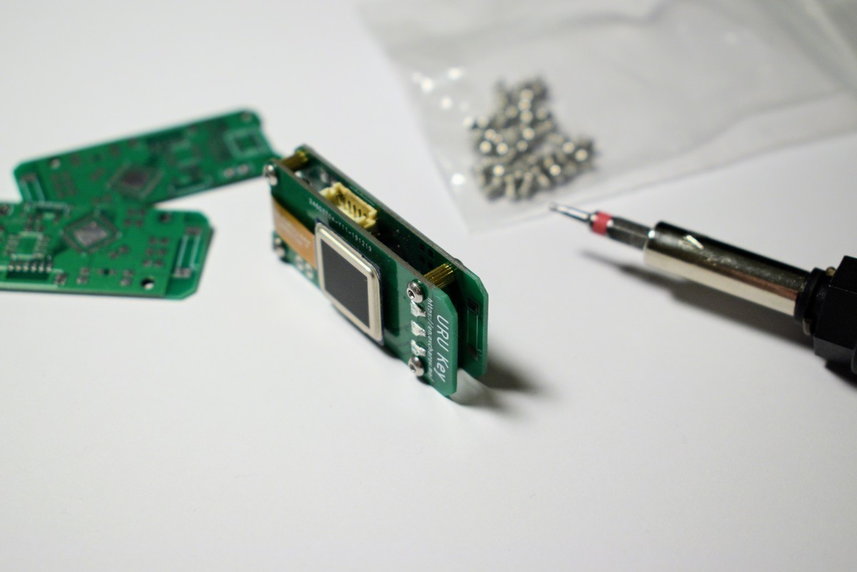
    Two versions of prototype boards together
    Two versions of prototype boards together

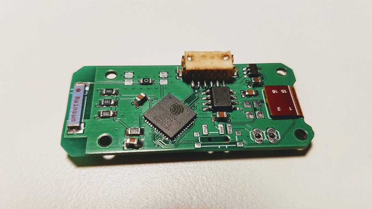
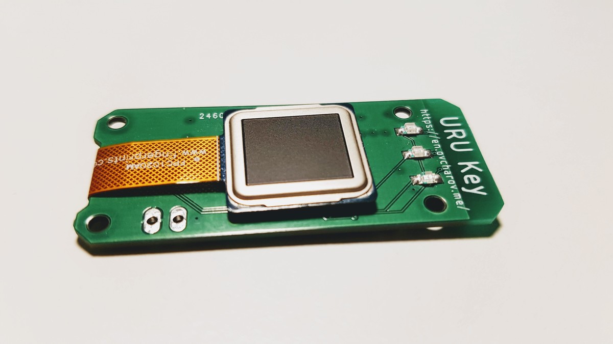
    I have skipped voltage regulator for now since I want to experiment with different ones on separate board. Connector to the UART fingerprint scanner was replaced with the connector to the FPC1020AM which was placed to the other side of the board.

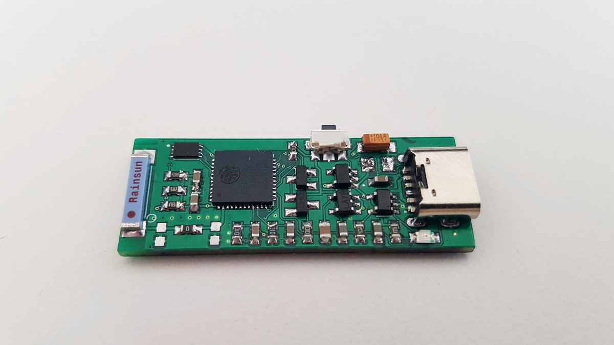
    URU Key FIDO2 Authenticator - Top Side
    URU Key FIDO2 Authenticator - Top Side
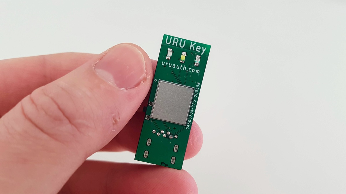
    URU Key FIDO2 Authenticator - Bottom Side
    URU Key FIDO2 Authenticator - Bottom Side

    To display different states of user interaction I have soldered three LEDs - red, blue and green. Blue one should be used to display different states of user interaction while red and green should display error and notification messages.

    Notification LEDs and Fingerprint Scanner
    Notification LEDs and Fingerprint Scanner

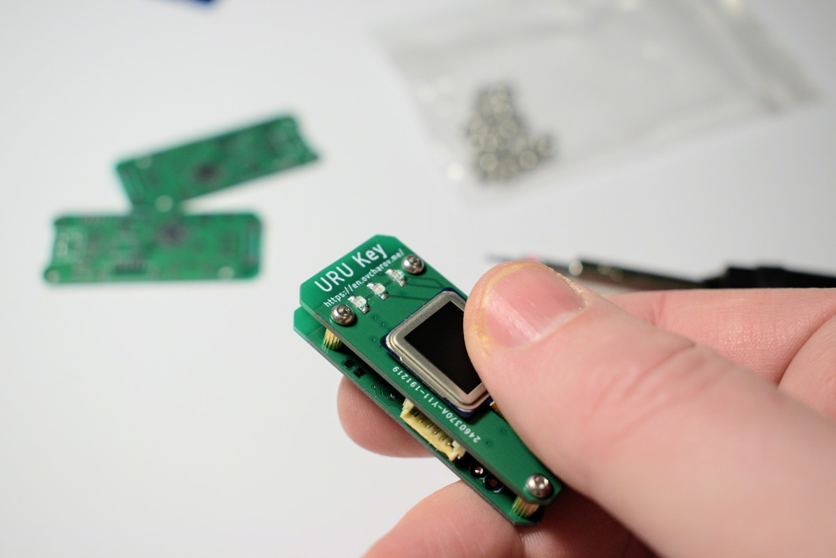
    The board features mounting holes so I started to think about putting it into a decent case. Meanwhile, the spare PCB placed with brass spacers provides a general look and feel of the future device.

    Holes for mounting the PCB
    Holes for mounting the PCB

    It’s not a huge step, really, but just a compilation of what I already had. Nevertheless, now all the small pieces work together as one device and the device started to get a shape. I can hold it in my hand, I can confirm authentication request with my finger and it makes me absolutely happy how it goes. Yes, I think now it’s time to give the project a name.

    Last summer, when I just started to think about making own FIDO2 Authenticator I came with the name for the project - “URU Auth”. “URU” is an abbreviation which reads as “You Are You” and I think this name fits quite well for the authentication device.

    What is the next challenge then? Now it’s time to experiment with the power source to make it really autonomous while keeping small and lightweight. And, still, I have to process and recognise fingerprint image.

  • Capture fingerprint image with FPC1020A scanner

    Andrey Ovcharov01/06/2020 at 15:57 0 comments

    Surprisingly, scanning the fingerprint image was not an easy task. I’ve spent several days trying to retrieve any data from the sensor except the hardware id but without any success. Apparently the task of processing raw images from the capacitive scanner is not a very common task and it was hard to find any code examples or documentation online.

    However, some search could help me to solve this problem. I have discovered that some branches of Android kernel have a special driver for the FPC1020A scanners written by the company Fingerprints. And, working with these sources could help me to find out that documentation I have is incomplete.

    First of all, the FPC1020A chip has at least four revisions requiring different setup procedures. Many of the setup values are real “magic numbers” as they are not described in the documentation and look like 64bit integer values. Probably the full and proper documentation could bring some light on this topic but I don’t have it at the moment.

    I did not write the code to detect which revision I have but just tried out one setup sequence by one. Suddenly, the revision A3 enabled finger detection and scanning functions.

    So, at the moment, I have a code for ESP IDF to work with both types of the FPC1020A scanners I have, detect the presence of the finger and receive a huge array of 8-bit values representing the fingerprint image. Not a big step, but a very important milestone - now the biometric part of the project moves from the hardware to software section - I need to find/build algorithms for recognition and matching fingerprints

  • Fingerprint scanner connection

    Andrey Ovcharov12/13/2019 at 11:40 0 comments

    There was a long delay after previous project update. As you might remember the current challenge is connecting to the fingerprint scanner for proper authentication of user. I have ordered two fingerprint scanner modules - FPC1020AM and FPC1020AP and, unfortunately, the delivery took more than month and a half. Nevertheless I have finally received them and the project continues. I was surprised how small and thin the scanners are.

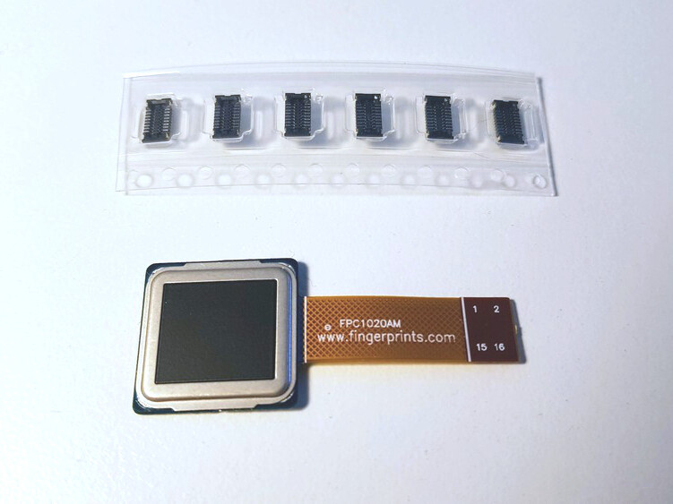
    Both devices are small and thin capacitive fingerprint scanners with resolution 192x192 pixels at 508dpi and SPI interface.

    FPC1020AM features flexible cable with flat 16 pin connector. Connector model is BM10NB(0.8)-16DS-0.4V(51) by Hirose.

    FPC1020AM module and Hirose connectorsFPC1020AP is the same scanner in LGA package and I’ve spent some time figuring out how to properly connect it.
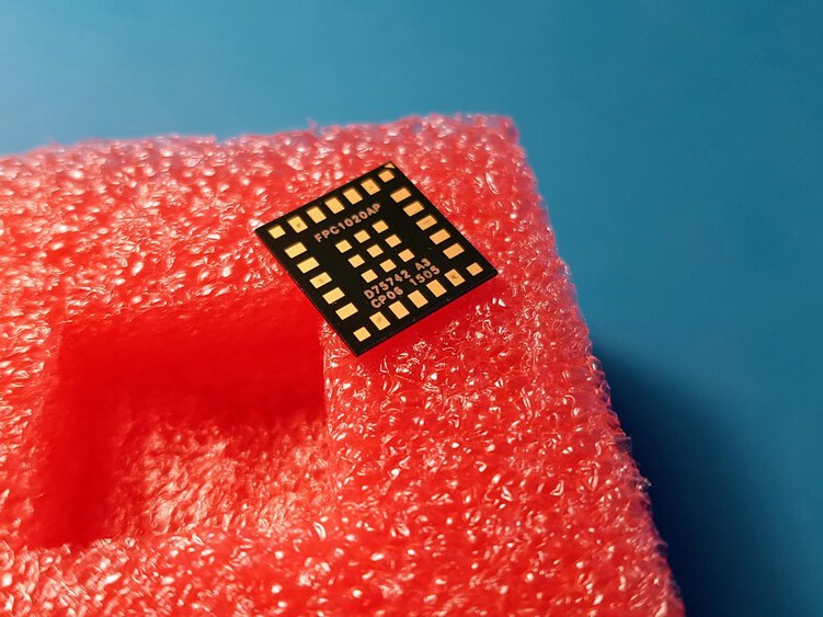
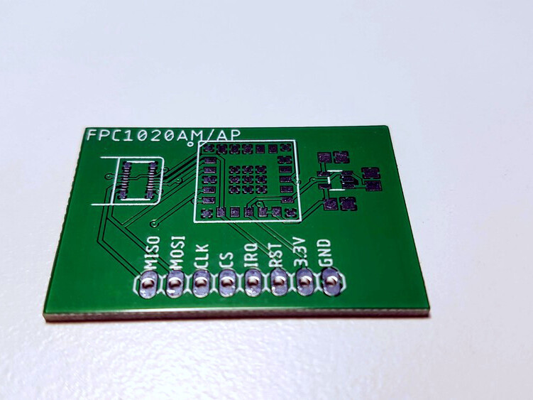
    FPC1020AP fingerpint scanner module

    More details on connecting these scanners to microcontrollers and corresponding Eagle CAD libraries are available in my personal blog

    To test both scanners I have designed a very simple PCB with a pin header and LP2985 1.8V voltage regulator with ceramic decoupling capacitors.

    Test board for FPC1020 fingerprint scannersThe board is connected to the ESP32 development board with four wire SPI interface.
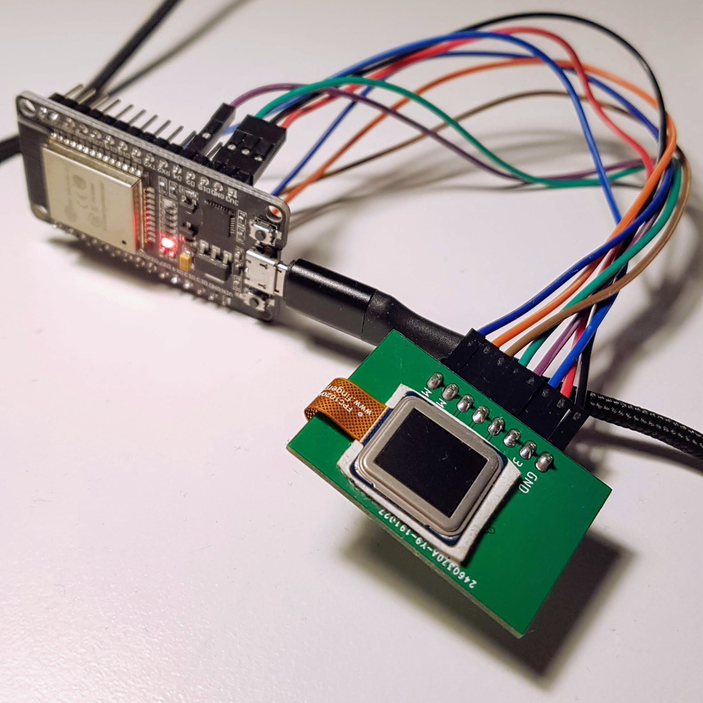
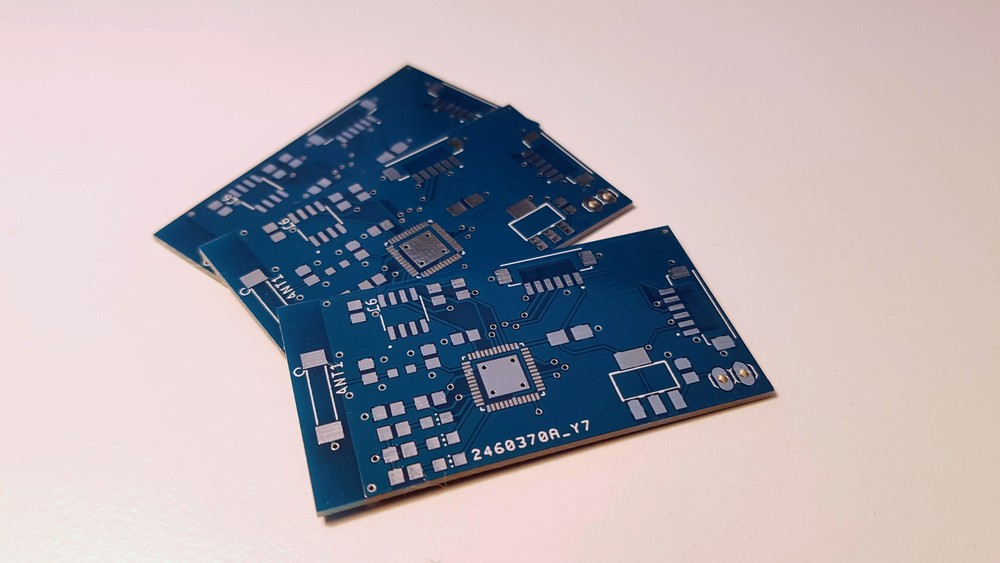
    I was able to write a script communicating with the board and receive proper hardware ID, as described in the datasheet.

    Next step is proper setup of the scanner and receiving the fingerprint image from it.

    Stay tuned! ✌️

  • First prototype build

    Andrey Ovcharov11/04/2019 at 09:30 0 comments

    After a few weeks of waiting the postal service delivered the PCBs for the device prototype. Usually I order my boards from the JLCPCB manufacturer and the quality is very good, as always.

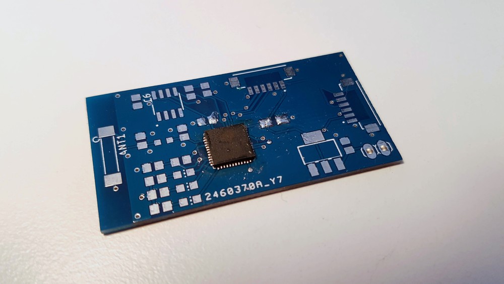
    PCB

    Of course, I could not resist and started to assemble the first board.

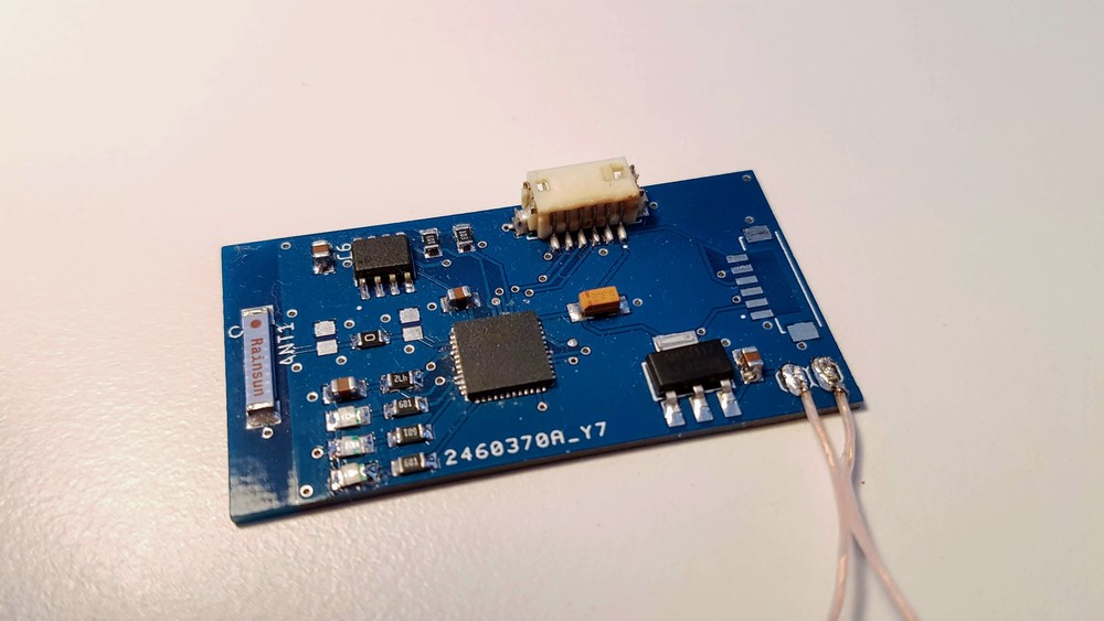
    ESP32 Pico D4 has LQFN package with contact pads under the chip body. It was first attempt to solder chips like this with the hot air gun. Tricky, but luckily YouTube is full of videos how to do it. The soldering paste works exactly as in the videos - the chip is magically centered on the board and excess solder is pushed out with the surface tension.

    Soldered ESP32 Pico D4

    Other components were soldered using the same method with soldering paste and hot air gun. The process is much more satisfying than working with usual components with pins. Later I plan to order special stencil for placing soldering paste more accurate and I want to build special oven for the reflow process. This should drastically improve the quality of my devices.

    Fully Assembled board

    The soldered board looks quite boring and with a lot of free space. I did not try to optimize it in any way for the first prototype and placed components very sparse. However, in the future I plan to use smaller 0603 components and smaller power regulators like AP2112.

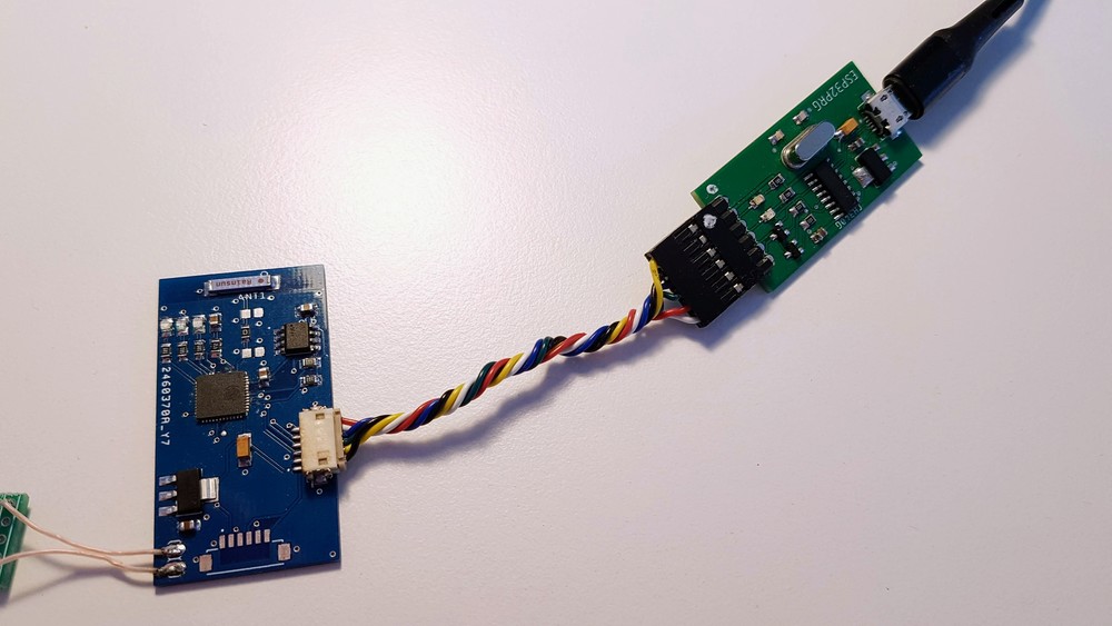
    I did not place any special connectors for the power, just the simple pads. I plan to experiment with different power sources like LiPo or CR2032 batteries so I do not want to stick to any particular connector at the moment. That’s why I’m connecting separate board with micro USB connector using just two wires.

    The connector for the UART fingerprint scanner is not soldered yet - I am going to make decision which one to use after experiments with different ones I have.

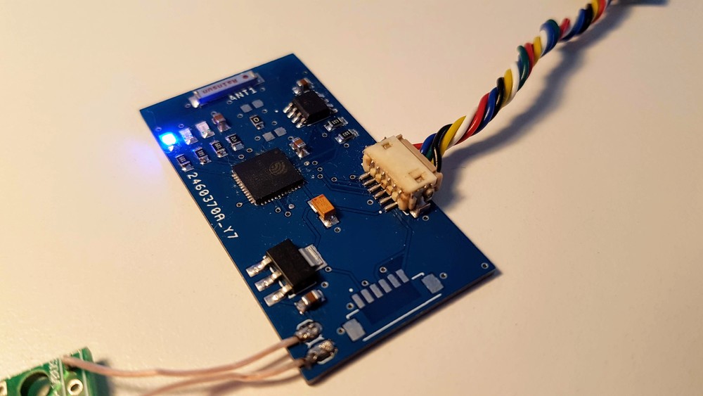
    The assembled board was successfully identified by ESP32 programmer. Flashing went smooth at the speed of 921600 baud. The device works exactly the same way as the development board and it is still able to pass both registration and authentication procedures I showed in previous video.

    What is more interesting - it’s still working without connection to the host computer powered from power bank. I think it’s a clear success at this stage - I already have small independent device which can be used for FIDO2 authentication. Yes, there are a lot of problems to solve, but still.

    Next step is going to be very complex and vital for the success of the whole project. I have two fingerprint scanners already and ordered two more. If I will be able to read fingerprint image and implement matching algorithm then I have all the building blocks and I can improve the device working on every block independently. Stay tuned!

View all 17 project logs

Enjoy this project?

Share

Discussions

the-Arioch wrote 01/11/2022 at 13:36 point

You said you won't opensource it due to biometrics.
But perhaps you can make a "URU Key Lite" without fingerprinting, but with a simple click-button (and maybe tiny screen in the freed from fingerprinting space), and perhaps a pair of USB + USB-C connectors for desktop uses ?

  Are you sure? yes | no

Paul wrote 09/21/2020 at 12:41 point

This is so cool! Are you planning to sell it or run a Kickstarter for it?

  Are you sure? yes | no

Andrey Ovcharov wrote 09/22/2020 at 07:25 point

Thank you!

I am thinking about selling but did not make a final decision yet.

  Are you sure? yes | no

John Gilmour wrote 06/03/2020 at 12:44 point

Hi Andrey, great project, I have not seen many people using the esp32-pico directly. It is usually a module.  Where did you get the information for the minimal esp32-pico layout and antenna circuit.

Just trying to learn some lessons for my sensor and display project more compact after my first design.

  Are you sure? yes | no

Andrey Ovcharov wrote 06/29/2020 at 08:47 point

Hi!
Sorry for late reply.

You can find information regarding minimal layout in the ESP32 hardware design guidelines here - https://www.espressif.com/sites/default/files/documentation/esp32_hardware_design_guidelines_en.pdf

  Are you sure? yes | no

breakeryu wrote 02/19/2020 at 10:08 point

great! it is wonderful!

  Are you sure? yes | no

Andrey Ovcharov wrote 02/22/2020 at 20:44 point

Thank you!

  Are you sure? yes | no

Similar Projects

Does this project spark your interest?

Become a member to follow this project and never miss any updates