 Vitaly
Assembled third version of PCB:
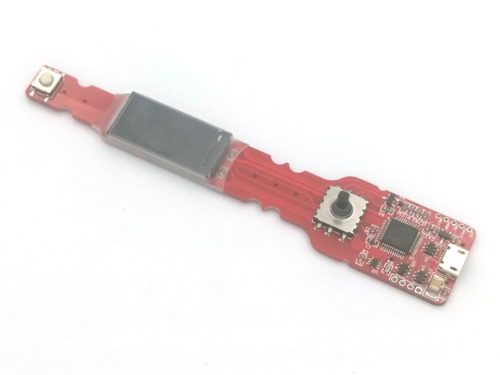
- Added current monitor (in theory, should help to autodetect retract size).
- Fixed BOOT pin control, to allow firmware upload via USB.
- Added holes for wire pins to lock plastic supports.
- Debug pins grouped in line.
My friend, second author of our sensor-less speed control for grinder decided to join this project too. He will help with drivers debug (current firmware runs in simulator only). And i will continue with reflow micro table for this time.
Sorry for slow updates - that's specific of OSS development. Instead of doing single project, i prefer to do multiple things in parallel. This allows to share efforts, and each can pick preferable parts where he is most qualified.
Discussions
Become a Hackaday.io Member
Create an account to leave a comment. Already have an account? Log In.
Good Day
How is progress going on this project, love the look of this. Very keen to put one together. I have just received the motor.
Wanting to know if you have had any other issues with the board before i order a board.
Thanks, great work.
Are you sure? yes | no
Hi! Development process is open, you can see every change on github. At current moment indicator/joystick/usb are alive, i will post new log record soon. Motor bridges and current sensor not tested yet.
If you are going to develop - PCB is ok. In other case i'd suggest to wait for sure.
Are you sure? yes | no