-
Trouble Shooting
08/14/2019 at 02:56 • 0 commentsI had the servo assembled and ready to start running the program that I wrote for the first iteration. Annnnndddd it would not move, just buzz..... What could limit the power to the motor? Obviously the first thing is the program is wrong. So I had code to send full power to the motor as startup. Still nothing. Ok, must be a bad board not sending the signal to the board. Nope, all is fine..... Ok, a signal to my mosfet is grounding and not opening. No conductivity between the gates and anything else. I have a current chopping feature on the TI DRV chip. Perhaps I miss calculated that value? Math checks out so I take off the resistors and wire in some wires to bypass this feature. Still nothing. By this point I had assembled and disassembled the servo 4 times. While it was probing around with the oscilloscope (looking for any information at this point) I noticed that when I touched the servo it would speed up slightly. So I then started poking around and then I touched the film between the board and the mounting case. Then I could make it go full throttle or almost to nothing by flexing the material. It turns out that the material that isolates the board from the aluminum sub-frame is slightly conductive. Who know (I definitely did not). Lesson learned, only use quality parts!
-
GUI Programing Part 1
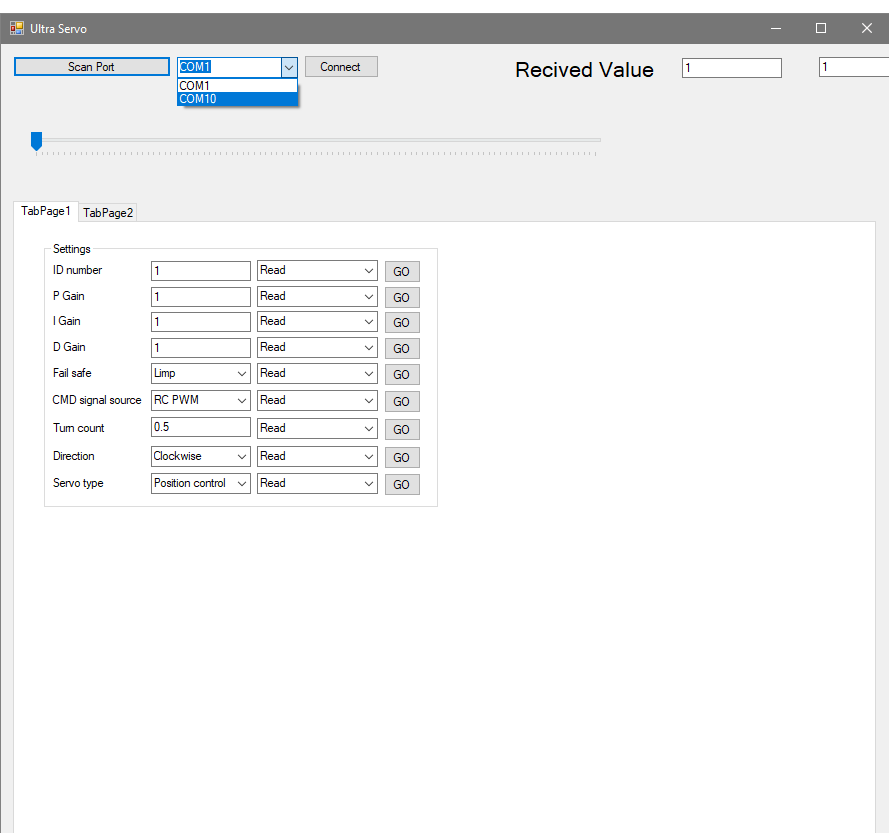
08/09/2019 at 02:39 • 0 commentsI decided that the best way to interact with the servo is to have a dedicated application. I did toy with the Idea of the user changing parameters in the Arduino sketch and re-uploading it to the servo. That's not a real polished product and will deter some hobbyists from the product. So I started to build the interface to read/write settings. Here is a screenshot of the GUI
![]()
The user can select read/write/perm.write for any of the settings. The difference between write and perm.write is how it is handled in the Arduino. The write changes a volatile variable only (will reset at startup) and the perm.write changes the volatile variable and the EEPROMPT variable. This was done to give flexibility to change a parameter multiple times without "wearing out" the EEPROMPT storage. This is particularly useful when using the servo in a robotics application that a master computer may change the PID gains multiple times per second.
-
Mechanial Redesign 1
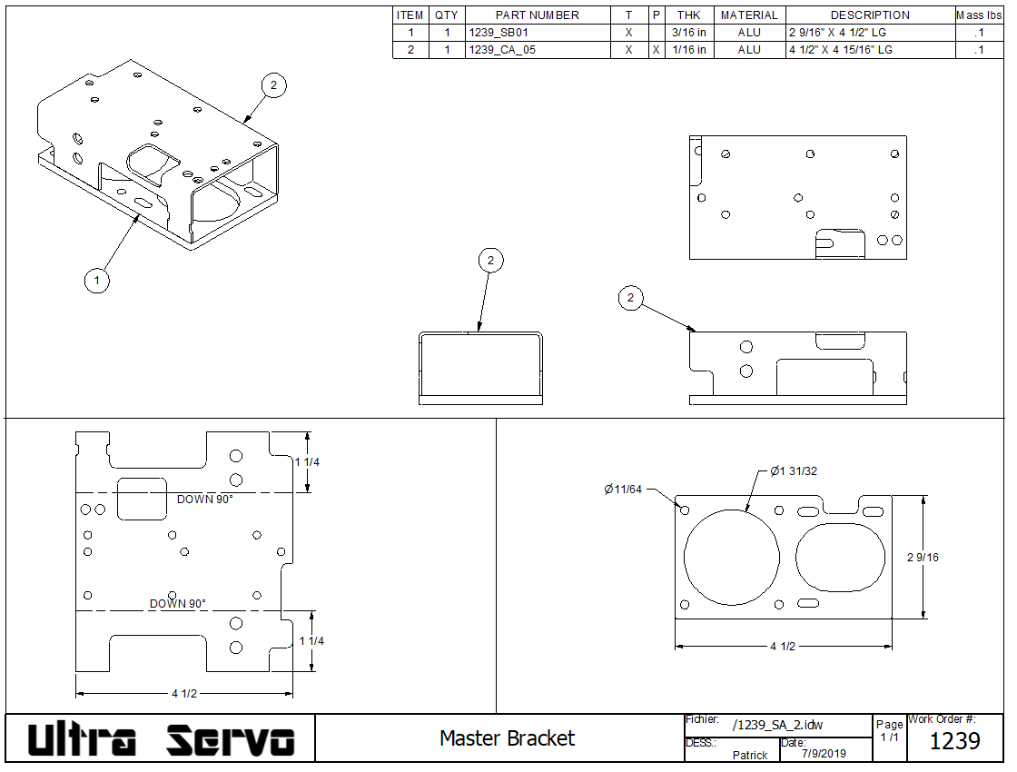
08/09/2019 at 02:26 • 0 commentsSince the position sensor now needed to be at the foot of the servo, all the brackets and mounting plates had to be redesigned. All the wire management was much more though out because the large diameter wire that supplies the servo is definitely a large item that needs consideration. The last iteration have too many parts to hold the components in place. The revised base plate was designed in 2 parts that welded together. The aluminum plates have multiple holes for mounting screws and reliefs for clearing the electrical components through hole mounting.
![]()
The two parts may seem simple but I have spent lots and lots of time to iterate the design to consider manufacturing tolerances, cable routing, belt routing and the ability to actually bolt it together! -
Board Redesign
08/08/2019 at 01:30 • 0 commentsRevamping the circuit board became very apparent when I was programming the second version of the servo that using an analogue position sensor was just not going to cut it. I ordered the AMS AS5600 breakout board. This 12 bit digital angle sensor made the positioning much more accurate and allowed to reliably detect when the servo has done a complete turn to allow for a multi turn function. This lead to design a board that incorporates the angle sensor in it. That cemented the position of the board at the foot of the servo.
Once all that was established, I created a second version with the Mega 32U4. This "Leonardo" controller was used because I wanted to eliminate the FTDI chip and..... The serial comms were underwhelming to say the least. It would be unthinkable to have someone re-program the servo only to have it lock up with the reset button buried deep inside the servo..... So, once again, there was one more revision to incorporate the good old Arduino UNO chip with the FTDI.
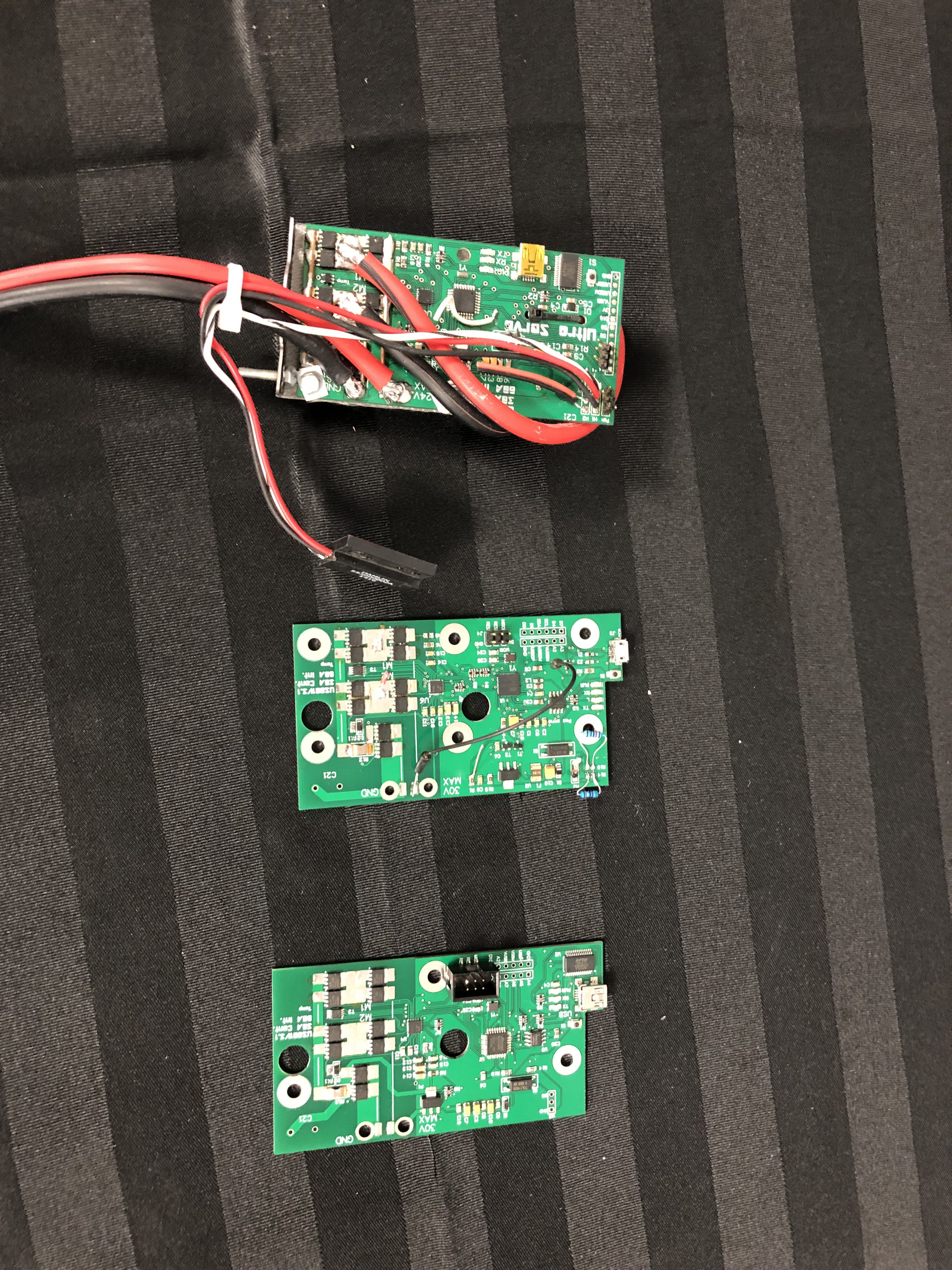
I had made another project that was plagued with ground noises and different ground potentials. It ultimately lead me to install an opto isolator that cured pretty well everything. This is why on this new board. I wanted to have this feature for the RC because this problem was very hard to trouble shoot and it can be easy to say "well your servo is acting erratically when...". This leads to hunting for non existent firmware issues.....Below is the progression of boards Oldest on top to newest at the bottom.
![]()
Ultra Servo V2.0
The intent behind the Ultra Servo is to give a maker or a robotics a powerful building block.
 patchartrand

