-
Rethinking loop tuning capacitors
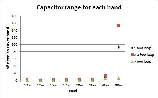
03/11/2022 at 15:22 • 0 commentsI have been rethinking loop antenna tuning. The evolution of this new direction started with the design of a "fine tuning" capacitor. Rather than microstepping a high voltage 100 pF variable capacitor, it could be easier to adjust for low SWR with a fine tuning ("bandspread") capacitor. I did some spreadsheets to see what value capacitor was needed. The results surprised me. Specifically, what size (capacitance range) variable capacitor is needed to tune each band with a 1 meter loop and a 5 foot diameter loop. One meter is a very common loop size. 5 foot diameter is the size I use on most bands. The answer is: under 15 pF for 40 - 10 meter bands. You need substantially more on 80 m unless you go to a 7 ft loop.
![]()
No wonder tuning can be a challenge given the small capacitance ranges. Here is a table of capacitance range for each band.
   Dia  3.34     5.00    7.00 foot
Band
10m     1.14     0.69     0.47  pF
12m     0.10     0.06     0.04
15m     0.75     0.46     0.31
17m     0.27     0.16     0.11
20m     1.97     1.19     0.82
30m     0.77     0.47     0.32
40m    13.17     7.97     5.48
80m   153.37    92.84     6.38
Note that the WARC bands (12, 17, 30 m) have narrow assignments, so their capacitance range values are smaller.
If we omit 80 m for now (not a very efficient band without a 7 foot loop), the largest variable capacitor we need is under 15 pF.
New thought: If you want just a few bands, think about fixed capacitors for band changing and a small variable capacitor for tuning. More on this later.
For testing this capacitance range, I am going to keep my large variable capacitor to change the band, but use a small capacitor for tuning. Next, I will design and build a small home-brew capacitor.
-
QEX rejected an article on this
08/01/2020 at 12:54 • 0 commentsQEX magazine rejected an article about the loop antenna and autonomous controller design. Sad, but not unexpected. Meanwhile, I have been using the loop antenna without the controller for FT8 on 40, 30 and 20 meters. I am using my old FT-100D mobile rig, which hates a SWR over 1.5:1. A small tuner helps bring that to 1:1 and lets me output up to 100W if I need that much power.
When COVID-19 is over I am thinking about building an entire radio into the antenna with the tuning controller. Why not? Wi-Fi will be used to select a frequency, TR switching and send audio for FT8.
-
Circuitry re-assembled onto a single circuit board
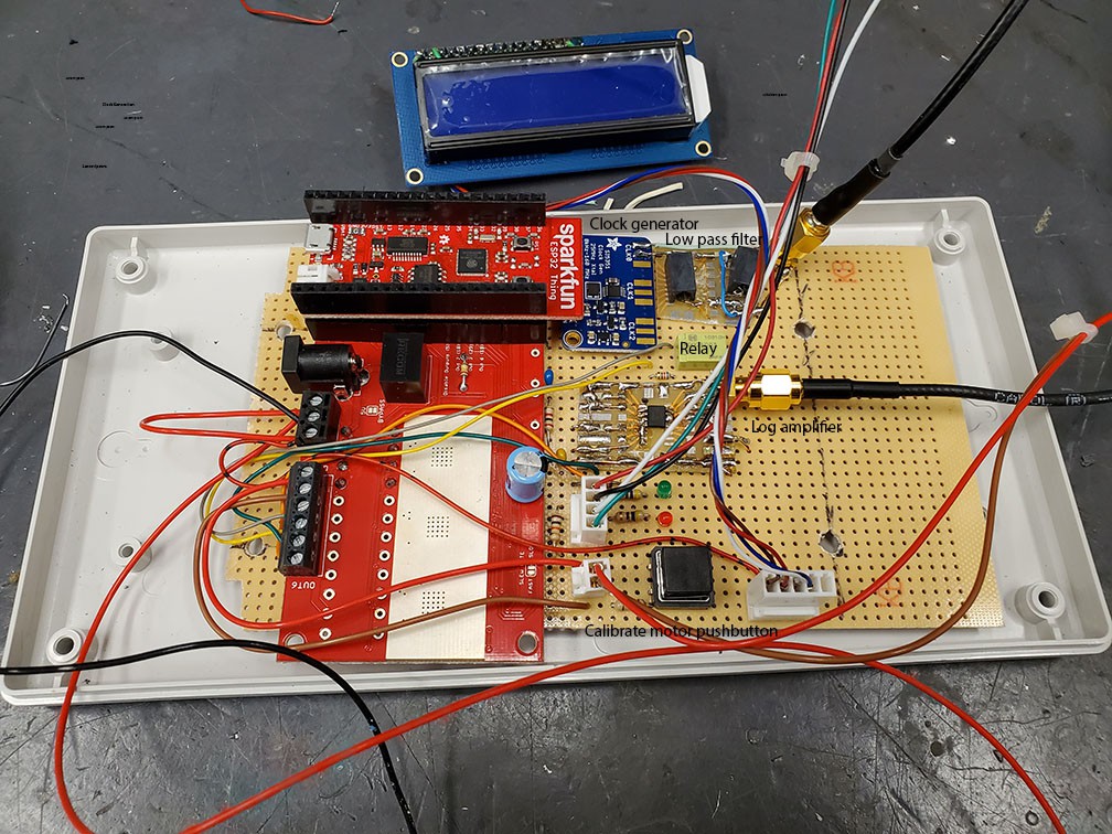
12/11/2019 at 19:31 • 0 commentsThe circuitry has been rebuilt onto a single board assembly. This version has two latching relays to short link coupling of the coupling transformers when the antenna is in use (up to 100 W operation). Hopefully, this will protect the log amplifier and the clock board.
![]()
I have a video of the prototype in operation, but it is too large at the moment. I will resize it and post it later.
-
Autonomous tuning is working
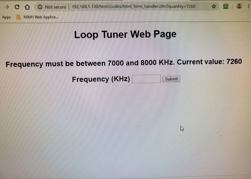
10/07/2019 at 22:49 • 0 commentsThe prototype autonomous motor controller is working well. Here is how it works. On boot up, the SparkFun ESP32 "Thing" looks for a specific WiFi. I use an inexpensive WiFi extender as a stand-alone access point not connected to the Internet. It reports the IP address on a 2 line LCD display. I use my cell phone to connect to the same access point. A simple web page allows me to type in the frequency and the controller automatically tunes the loop to the desired frequency.
![]()
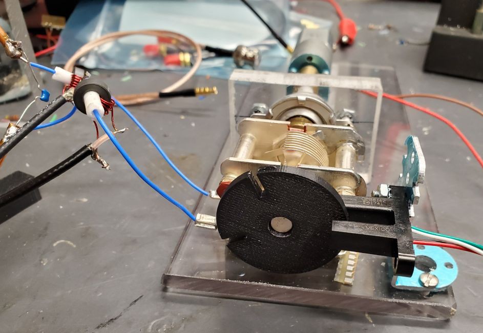
I made a custom 3D printed hub on the variable capacitor to locate the fully meshed position. Note the IR detector. The slots in the hub are located at 0 deg and 45 deg. One slot aligns with the fully meshed position.
![]()
Once the fully meshed position is located, the frequency of that position is measured by sweeping the clock generator and following the output of the RF log amplifier. From that point on the direction of movement can be associated with the increase or decrease of resonant frequency.
During tuning, the desired frequency is approached at full speed as the resonance is detected with repeated frequency sweeps. The motor slows when the system is getting close to the desired position. The motor is stopped near the final position. It is then "jogged" in small steps (in either direction depending on the frequency reading). This can get the frequency to within about 5 KHz of the target.
Note in the picture that there are now two toroids used. One is for the clock generator and one is for the log amp. A latching relay shorts the secondary of both transformers to protect the tuning circuitry during full power operation of the loop. This shorting mechanism is as yet untested.
My next task is to power the whole system from a Lipo battery. It requires 5 v at about 30 mA when operating. I need a control for the LCD backlight, but otherwise it should be able to idle a relatively low power. I am worried that the 3.8 v to 5 v converter may inject noise at the RF frequencies of the loop.
-
Motor test program
09/10/2019 at 15:17 • 0 commentsMotor test program
Since the last update, I finished writing a motor test program. The documentation and examples for ESP32 Arduino PWM (called ledc, because it was intended for controlling LEDs) are unclear. Using a PWM frequency of 30 KHz and a 8 bit resolution, I can get control of the motor speed reasonably well. I found that useful speeds range from PWM of 50% to 100% duty cycle. The examples on the Internet have bugs. It was actually unclear from the documentation if a PWM value of 0 is full ON or full OFF. Since I am using a H-bridge to run the motor forwards and backwards, I discovered that a PWM of 0 is required for the LOW side of the bridge. During the first testing I was unable to get the ADC to record motor stall (high current), so I am not monitoring current at the moment.
// MotorTest - A. Mitz // Much of the code from SparkFun Thing Power Control Shield // Spin the motor from low to high speed, then do same in reverse. // Pins defined by ESP32 Thing and the Power Control Shield #define CTRL_1 25 // Output 1 (Motor -) #define CTRL_2 18 // Output 2 (Motor +) #define forward true #define reverse false unsigned long timer_count; unsigned long timer_done; int adcVal = 0; boolean runMode; // 0-Forward, 1-Reverse // Useful motor speeds based on PWM controller // index 0 to 6. Value of 0 is OFF. Value of 6 is full speed // approx: 0=off, 1=50%, 2=60%, 3=70%, 4=80%, 5=90%, 6=100% const int MOTORSPEED[] = {255, 125, 100, 75, 50, 25, 0}; // useful speeds from 0 to fast const int MAXSPEED = 6; int speed; // PWM settings const int PWM_freq = 30000; // 30KHz const int PWM_resolution = 8; // Number of bits of resolution (8 bits = 0 to 255) // Setting for forward direction PWM const int forward_PWM_Channel = 0; // chan 0 to 15 int forward_dutyCycle = 255; // Max for 8 bits // Setting for reverse direction PWM const int reverse_PWM_Channel = 1; // chan 0 to 15 int reverse_dutyCycle = 255; // Max for 8 bits void setup() { // Initialize UART Serial.begin(115200); // Initialize driver pins pinMode(CTRL_1,OUTPUT); // Forward part of H bridge pinMode(CTRL_2,OUTPUT); // Reverse part of H bridge // configure PWMs ledcSetup(forward_PWM_Channel, PWM_freq, PWM_resolution); ledcSetup(reverse_PWM_Channel, PWM_freq, PWM_resolution); ledcAttachPin(CTRL_1, forward_PWM_Channel); ledcAttachPin(CTRL_2, reverse_PWM_Channel); // Initialize timer timer_done = millis()+4000; // 4 seconds // Initialize motor direction runMode = forward; speed = MAXSPEED; forward_dutyCycle = MOTORSPEED[MAXSPEED]; reverse_dutyCycle = MOTORSPEED[MAXSPEED]; ledcWrite(forward_PWM_Channel, MOTORSPEED[MAXSPEED] ); ledcWrite(reverse_PWM_Channel, MOTORSPEED[MAXSPEED] ); digitalWrite(CTRL_1,HIGH); digitalWrite(CTRL_2,LOW); delay(250); // delay (during current spike) in case ADC is used Serial.println("Initialization done"); } // setup void loop() { // -- timer service -- // timer_count = millis(); // get ms since program started if (runMode == forward) { /* Does not work // Sample I-Sense 2 adcVal = analogRead(34); // hard-wired port Serial.println(adcVal); if(adcVal > 100) { // see if the motor is stuck runMode = reverse; // Reverse if stuck // Stop motor for 1 second digitalWrite(CTRL_1,LOW); digitalWrite(CTRL_2,LOW); delay(1000); timer_done = timer_count+2000; // restart timer digitalWrite(CTRL_1,LOW); digitalWrite(CTRL_2,HIGH); delay(250); // delay (during current spike) } // if adcValue */ if (timer_count >= timer_done) { // Next slower step? speed--; // Slow down Serial.print("Forward speed = "); Serial.println(speed); if (speed == 0) { // time to reverse? // Stop motor for 1 second Serial.println("Range done. Stop motor"); digitalWrite(CTRL_1,LOW); digitalWrite(CTRL_2,LOW); delay(1000); // reverse Serial.println("Reversing"); runMode = reverse; // Reverse direction speed = MAXSPEED; ledcWrite(forward_PWM_Channel, MOTORSPEED[0] ); // Low output set to zero ledcWrite(reverse_PWM_Channel, MOTORSPEED[speed] ); digitalWrite(CTRL_1,LOW); digitalWrite(CTRL_2,HIGH); delay(250); // delay to prevent current spike from giving a false positive on the ADC Serial.print("Reverse Speed = "); Serial.println(speed); // Initialize timer for reverse direction timer_done = millis()+4000; // 4 seconds } else { // slow down Serial.println("Slowing"); ledcWrite(forward_PWM_Channel, MOTORSPEED[speed]); timer_done = millis()+4000; // 4 seconds } } // if timer_count done } // run mode forward else { // Reverse /* Does not work // Sample I-Sense 2 adcVal = analogRead(34); Serial.println(adcVal); if(adcVal > 100) { runMode = forward; // reverse to Forward // Stop motor for 1 second digitalWrite(CTRL_1,LOW); digitalWrite(CTRL_2,LOW); delay(1000); timer_done = timer_count+2000; // restart timer digitalWrite(CTRL_1,HIGH); digitalWrite(CTRL_2,LOW); delay(250); // delay (during current spike) } // if adcVal */ if (timer_count >= timer_done) { // Next slower step? speed--; // Slow down Serial.print("Reverse speed = "); Serial.println(speed); if (speed == 0) { // time to reverse (back to forward)? // Stop motor for 1 second Serial.println("Range done. Stop motor"); digitalWrite(CTRL_1,LOW); digitalWrite(CTRL_2,LOW); delay(1000); // reverse to forward direction Serial.println("Reversing to forward direction"); runMode = forward; speed = MAXSPEED; ledcWrite(forward_PWM_Channel, MOTORSPEED[speed]); ledcWrite(reverse_PWM_Channel, MOTORSPEED[0]); // Low output set to zero digitalWrite(CTRL_1,HIGH); digitalWrite(CTRL_2,LOW); delay(250); // delay to prevent current spike from giving a false positive on the ADC // Initialize timer for forward direction Serial.print("Forward Speed = "); Serial.println(speed); timer_done = millis()+4000; // 4 seconds } else { // slow down Serial.println("Slowing"); ledcWrite(reverse_PWM_Channel, MOTORSPEED[speed]); timer_done = millis()+4000; // 4 seconds } } // timer done } // else reverse } // loop -
Automatic tuning of Loop antenna: Sweeping the antenna, identifying resonance
08/30/2019 at 15:31 • 0 commentsSome interesting progress with automatic tuning. To review, I have modeled the 40 meter loop antenna with a coil made from thin copper tubing. Initial testing is with a 100 pf capacitor. Later testing will be with a motor-driven variable capacitor. A sweeping RF signal is coupled to the tuned circuit with a nearby multi-turn link that is roughly 50 ohms at 7 MHz. (This simulates the exciter loop of the loop antenna.) For detecting resonance, the signal is sampled with a FT-43 toroid transformer. The primary is made by passing a wire through the toroid. The secondary is a tuned link with magnet wire.
The current goal is to find the resonance of the model loop antenna. The antenna is swept in 10 KHz steps. The microprocessor is a SparkFun ESP32 "Thing". It drives a Si5351 clock generator. The initial testing was done with the raw square wave output. That seemed to work well, but for good measure the output is now filtered above 20 MHz. The 2nd harmonic is still present at low sweep frequencies (e.g., 6 to 9 MHz => 12 to 18 MHz). Still, it is a much cleaner signal with most harmonic content suppressed by 20 to 40 dB. I think I did the design with AADE Filter Design and Analysis, then I put the filter into National Instruments Multisim for further testing.
Power readings come from a AD8307 log amplifier and are sent to the ESP32 Analog ADC1-0, however, that channel conflicts with the Sparkfun Power Control Shield that will be used with the tuning motor. That will be resolved shortly.
![]()
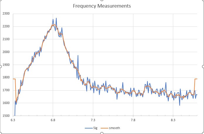
The jagged blue line is the raw data recorded by the ESP32. Units are byte value collect the the 10-bit A/D converter. I tested a variety of smoothing functions. I think this is a 5 point Savitzky-Golay filter. In the current version of the software, I first reduce the data set by selecting only data above the average of all the values. This sets the range for finding the peak. Then I use a 9-point Savitzky-Golay first derivative smooth. The peak is located with linear interpolation between values on either side of the zero crossing of the derivative. I will add a plot to show the peak finding later.
-
Prototype Loop Antenna
07/27/2019 at 23:46 • 0 commentsI found a 120 pf transmitting variable capacitor and mounted it into a NEMA box. (See building notes.) I cut a 5 foot loop from LMR-400 and soldered UHF connectors on the ends. I always do a careful job with coax connectors. I don't even have to connect the center pins in this design, but I soldered it carefully, anyway.
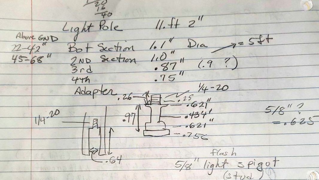
The antenna is supported by an 11-foot lighting pole. I designed 3-D printed clamps for each section of the telescoping pole (see building notes) and printed out a set. Here are my notes on the pole, including the stud on top.
![]()
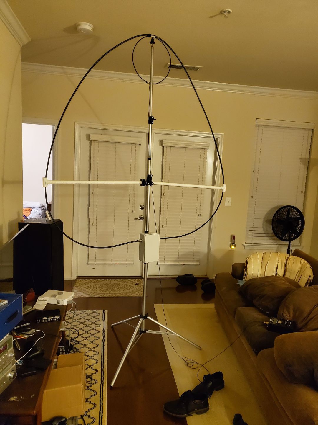
The loop did not fit well inside my apartment, but I was able to get some resonance measurements.
![]()
The cross arms are PVC. The loop is more round when the arms are on the next tube up. The excitation loop is LMR-200 with the center conductor of one end tied to the shield of the other end. A BNC female Tee connector ties it to the coax feedline. J-B Weld KwikWeld two-part epoxy did an excellent job of sealing the joint and mechanically protecting the junction.
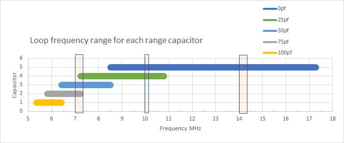
The two-section variable capacitor is effectively wired in series, giving about 50pf of adjustment range. The loop and capacitor tune from about 8.5 MHz to 17.3 MHz. For further work, I broke that into a simple model:
Equivalent capacitance = Cv + Cs + Ca
Cv = 0 to 50 pf variable
Cs = "stray" capacitance = 16 pf
Ca = fixed RF capacitors (HT50 doorknob) I add to set the rangeThe effective inductance, L = 5.3 uH.
This simple model has been very effective.
![]()
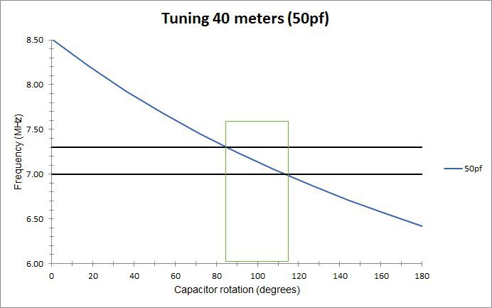
A 50 pf added fixed capacitor (Ca) gives me excellent coverage of the 40 meter band (7 to 7.3 MHz). The 40 meter band tunes over 30 degrees of rotation of the variable capacitor (which has a reduction drive on it). That is 8.4 pf out of 50 pf.
![]()
Without and added capacitor it is possible to tune 30 and 20 meters, but they only cover 2 and 4 degrees of rotation (0.56 and 1.12 pf), respectively. That is a tiny fraction of rotation. I looked at some 100 pf vacuum variable capacitors and they provide about 10 pf per turn. I am thinking about a 10 pf "bandspread" capacitor, which would eventually be motor driven.
Meanwhile, I took the prototype antenna to a friend's house. We turned to 10.136 MHz with 50 W and tried answering a DX call with FT8. The first contact was Ghana. Ok, that meets expectations. 40 meter SSB QSOs were between 1 and 2 S-units below that of an end-fed dipole. That agrees with my earlier evaluation.
Note, the very first version of the prototype used high voltage monolithic ceramic capacitors rather than RF type capacitors. They did not handle the RF current above about 8 W. As they heated up, the loop de-tuned and the SWR rose rapidly. The efficiency was probably poor at the higher powers, as well. Using the RF doorknob capacitors fixed that problem.
-
What hams want
07/26/2019 at 15:53 • 0 commentsShort loop antennas, especially for portable operation, are well described in magazine articles and on the Internet. Yet, most hams don't quite understand their limitations. If you want to be disappointed, operate a QRP rig on 40 meters with a 3 foot diameter loop. I did not understand this when I started, so I plotted some data to see for myself.
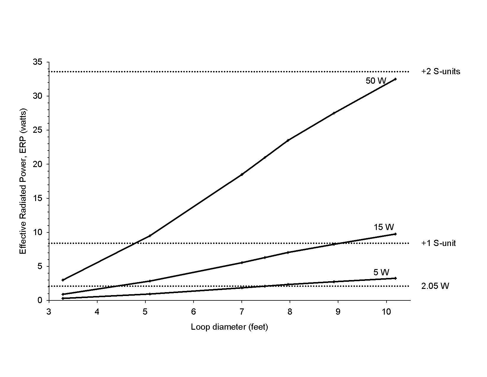
This what-if graph shows two very important features of 40 meter loop antennas. First, if you use a 3 foot loop with 5 W on 40 meters, your ERP is minuscule. I have marked a 2.05 W horizontal dotted line to indicate the minimum ERP I would tolerate for SSB operation. Note that with 5 W, you need a loop at least 7.5 feet in diameter for that ERP.
The second feature is power. Most portable 3 foot loop antennas are not designed to handle 50 to 100 W. With a loop that small you need a large capacitance. The capacitance must be variable and with 100 W the capacitor must safely handle 2 to 3 kV. A larger loop improves efficiency and reduces the capacitance. Still, the amount of power has a substantial effect.
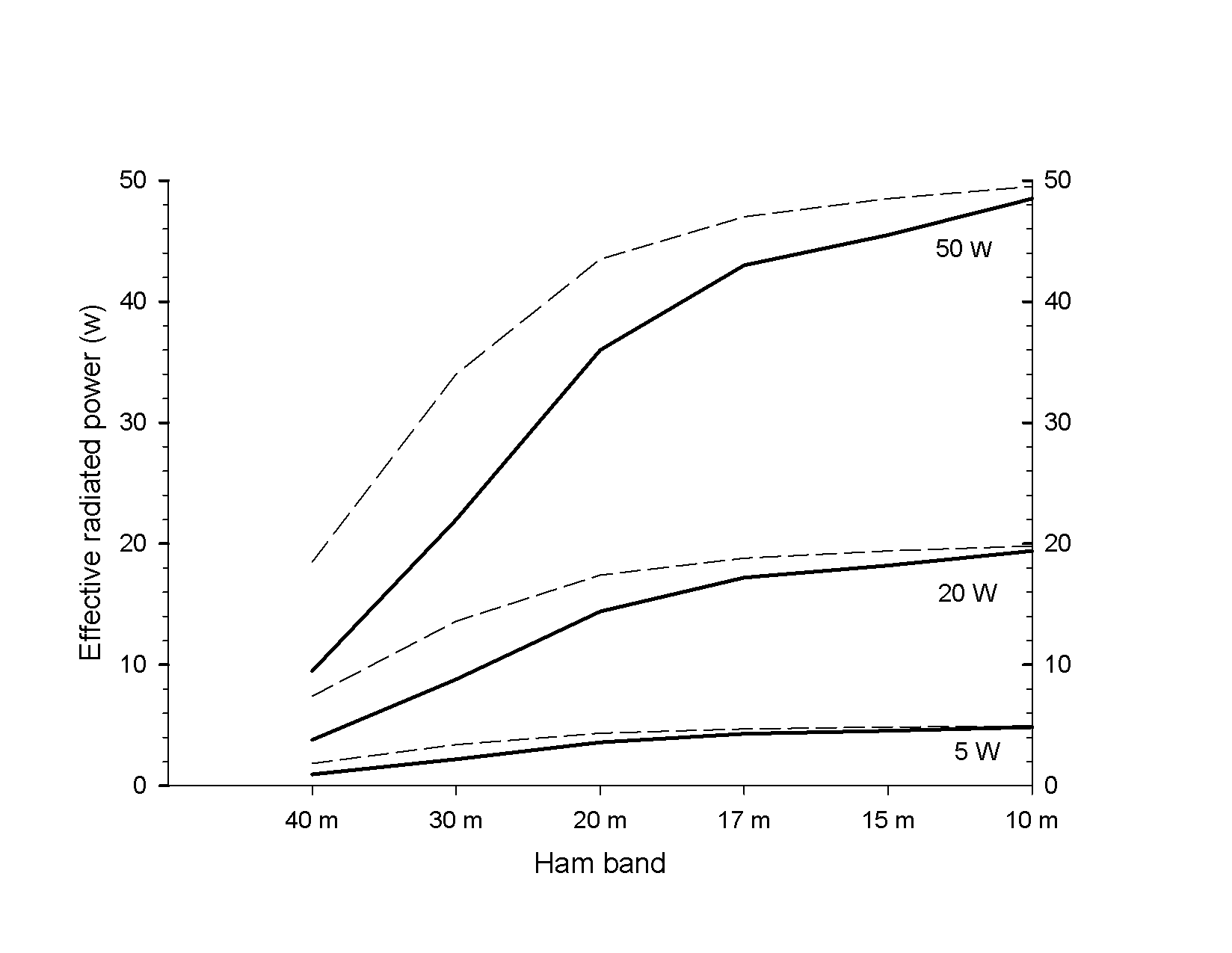
A 5 foot diameter loop make with LMR-400 coaxial cable is a practical solution for a portable antenna. The next graph shows me the performance on multiple ham bands.
The solid lines show the performance with a 5 foot diameter loop. The dashed lines show the improved performance with a 7 foot loop, although that gets to be a cumbersome size. There are two things to notice. First, the curves take a bend at 20 meters. At 20 meters and above, these loops are pretty efficient. Below 20 meters, efficiency really drops. Second, power has a dramatic impact on ERP. Of, course, it should. On 40 meters, I can squeeze out 10 W ERP with a 50 W transmitter. but even nicer, I can get rather good performance on 30 and 20 meters if I can use 20 W or more.
These graphs address my first two goals. Why people running 5 to 15 W on 40 meters are often disappointed with loop antennas, and what I need to meet my own expectation of enjoying portable operation on 40, 30 and 20 meters.
Basic HF Short loop antenna and some design notes
A portable loop antenna that works well on 40 through 10 meters. This basic design is advanced in my other projects.
 Andrew Mitz