To make the experience fit your profile, pick a username and tell us what interests you.
We found and based on your interests.
For quite some time I got hung up on the acrylic bending aspect of this project. In my head, I thought I needed a really small bending apparatus, complete with hinges. The project sat fallow for a while, until I saw Eric Strebel's videos on working with acrylic. All he had was basically a single wire (albeit a fancy water-cooled one), that he used to heat acrylic, after which he put it in a form to shape it. It's got a lot of great tips and you should check it out.
I made my own fancy hotwire jig out of some scrap wood, screws, a spring, nichrome wire, and a GameCube power supply. I only burned myself once with it!
It looks pretty dangerous, but I sized the wire to get the right current flow and the wire itself doesn't hold a lot of heat. I can touch the wire pretty shortly after disconnecting the power, so a lot less fire risk than one might expect. Only catch is that I have to make sure to unplug it when I'm done, but I should be doing that anyways.
Just look at the difference between the previous one (right) and the current approach (left). The striations and deformation from heating the whole piece are totally absent in the new one.
Next, I need to spin a new version of the board. Since I last worked on this project, I've switched from Eagle to KiCad, so I need to port this project to KiCad. I'd also like to switch my ATTiny85 from a QFN package to an SOIC package to make it easier to solder by hand.
I might even play around with a board spin made on my small CNC router. I suspect that soldering SOIC packages without solder mask will be a nightmare, but might learn something.
* By perfected I mean within spec.
One of the big unknowns (well, to me) about this version of my nametag was whether I could successfully heat bend the acrylic such that the light would travel around the 180 degree bend. I decided to give this a try today.
First, I laser cut a flat acrylic piece with my name engraved on it. The acrylic piece had an extended rectangular portion that I meant to bend around. I decided to set the length of that to the distance I needed the acrylic to wrap around to touch the LEDs if I was making perfect right angle bends (obviously an impossibility).
Second, I sandwiched the acrylic piece between two of the spare name tag PCBs with sheets of parchment paper between the PCBs and the acrylic. I reasoned that this would keep any of the lead from burning into the acrylic or leaving impressions. The parchment paper turned out to be a mistake.
Finally, I heated the whole assembly to around 300F in a toaster oven (one I don't cook food in), took it out, and bent it against a surface, holding it until it cooled off.
The good news is that plenty of light made it around the bend, so this is going to be a workable project.
The bad news is that my technique needs tweaks. Because I heated the entire piece of acrylic, some parts ended up deforming that I hadn't anticipated. The whole middle section ended up shifting with the tab, which means the top edge looks droopy.
The parchment paper also ended up leaving it's own impressions in the acrylic. They might not be noticeable from a distance, but I'm going to notice them every time I look at it.
I think the next thing to try is a similar assembly, but this time using a heat gun to try to heat only the tab needing bending. It might even be sensible to periodically dip the rest of the assembly in cool water the prevent too much heat from sticking around in the copper.
I finally decided to take the plunge and make my name tag programmable. I'm using an ATTiny85 in a QFN package coupled with IS31FL3218 LED driver (I2C) in a SOP footprint, and 155124M173200 RGB right-angle LEDs. The LED driver is PWM dimmable and has 18 channels (twice as many as I need). I also added a tact switch so I can potentially cycle through different display patterns. The LiPo charging circuit is identical, albeit re-positioned.
I had some difficulty soldering the board. I tried lasering solder stencils out of mylar, but had some trouble getting the solder paste to stick to the board instead of my stencil. The laser left slightly ragged edges (unusual for lasers, but I don't usually use them on this scale), which may have caught the solder paste when I went to remove the stencil.
All of the RGB LEDs ended up tombstoned out of the oven (basic toaster oven) and had to be reworked with a hot air station. It appeared that the ground pad of the ATTiny85 also ended up bridged to the other pins, so that also had to be reworked. Finally, it turns out the manufacturer's suggested footprint for the LED driver was a bit too small.
I'll just use a hot air station for the whole thing if I make another one.
Following the manufacturer's description of the registers and auto-increment features, I put together a test sketch (using Arduino IDE) meant to turn all of the LEDs on and off...
No signs of life, probably should've at least included a status LED of some sort.
Next, I uploaded a sketch that blinked one of the pins broken out to the programming header and watched the voltage change with my multimeter. That worked just fine, so I knew the problem was either with my code or the LED driver.
I consulted a friend at my makerspace who knows much more than I do about these things. He found a test sketch from the manufacturer, not using the auto-increment feature (and dividing the I2C address in half, which I don't understand). With a few tweaks (Wire.h -> TinyWireM.h) I got that code to run and flash my LEDs, which confirmed that my code was the issue.
I removed the auto-increment feature in my code (and also divided the address by 2, again, don't understand that) and was able to get the code running smoothly.
The next difficult part is figuring out how set up the interface for the LEDs in such a way that I can easily create the light patterns I want. I suppose I'll need to figure out which patterns those are first.
Once I have a couple of patterns, it'll be easier to debug a state machine using the button. I'd like to be able to switch between patterns using that button.
Finally, I need to figure out all of the non-electrical components, like the housing and heat-bent acrylic.
First LiPo version of my name tag was great, but it didn't really offer me the opportunity to customize for different events. With a small tweak to the layout, I made a new board with a generic rounded rectangle layout. Now I can attach different acrylic panels with relative ease.
The acrylic sandwich layers were tricky to cut last time with a laser, so this time I opted for a 3D printed sandwich layer to tie all of the parts together. Took some fiddling with printer settings (horizontal expansion) to get the pieces to fit together nicely right off the printer.
Obviously the next step is making this name tag fully programmable with RGB LEDs. I've seen some that are essentially just 3 LEDs packaged together and others, like the WS2812s that have a little more smarts. I'm concerned about battery life, so I'll have to look into which is more efficient. I also need to learn about programming smaller microcontrollers. I'm thinking I'll start with an ATTiny85.
New boards arrived and I soldered them all together. I discovered the SOT32 footprint of the battery charging IC and the micro USB jack were both really tough to solder. I bridged a few contacts a few times and had trouble fixing them. Flux certainly helped fix things.
The lights show up WAY better than they did with the CR2032s. Before, the lights were really only visible when the lights were dim, now they're visible all the time. (Note: this picture is with a bright light shining right on the board.)
There are two downsides to the current setup:
First, I had to make the whole thing bigger to accommodate the battery, which makes for a rather large name tag. I think I might add a second magnet so the name tag doesn't tilt downwards.
Second, the battery life isn't great, on the order of a couple of hours. I might be able to increase the resistance in series with the LEDs to eek a little more battery life out of it, but I really want to just add more juice so I can keep it nice and bright.
Next up is a more generic board so I can use this places other than the makerspace.
I'm finding that this name tag eats up a lot of CR2032 batteries and the brightness of my LEDs is limited by the amount of current those batteries can source. The next version will be LiPo powered.
Switching to a LiPo battery will not only be a little easier to work with than swapping out coin cells but also I might eventually be able to make the backlit version work with more current going to each of the LEDs.
I've done some research on what's needed to use a LiPo battery and the consensus seems to be that there are three extra components needed:
The first two can be combined into a single chip. I looked around and decided to go with an MCP73812T. I'm honestly not sure how I arrived at that as an option, but the datasheet makes it seem like it'll work for my purposes. I could be totally wrong about this, so you might not want to imitate me.
The last one, overdischarge protection, seems to be a separate part. I found that the LiPo battery I ordered (ASR00007 from TinyCircuits) already has overdischarge and overcharge protection, so I won't be adding a separate component for that.
I've ordered all of the parts, so the next step is to model all of the footprints in Eagle and put together the schematic.
At first, this name tag project was meant to lend me an air of credibility when teaching woodshop classes at Decatur Makers. I'm a relatively young-looking guy and anticipated that some folks might wonder "what is this child doing teaching me woodshop safety?" so I designed a tag I could wear for classes. I also realized that other members could make these tags so it would be easier for our members to get to know each other.
The first version had my full name, the Decatur Makers logo, and some icons that were meant to show the areas of the space I was an expert in (woodshop, Arduino, and laser in this case). I lasered it out of some plywood and added some blue/green paint to the etched areas.
This one looked ok to me, but I wasn't thrilled with how the paint wicked out into the surrounding wood. The whole thing also just felt a little too subdued. I really wanted it to be easily legible from a distance.
To fix the issue with color bleeding into the surrounding wood, I put a thin coat of water-based poly on first. I tried another one with a deeper engrave that I then filled with epoxy, which I hoped would make it pop a little more.
Although the epoxy did stand out a little better, I didn't like the sanding process to get the epoxy to look decent. The whole thing also started to feel a little busy to me.
I decided to drastically simplify the whole thing, making the name stand out more by eliminating some of the busy-ness. I got rid of the icons on the bottom and removed my last name, leaving just a larger first name. I coated this one in a few coats of water-based poly and attached a name tag magnet I found on Amazon.
I really like this version and still wear it pretty regularly. It's not terribly flashy, but it does the job of a name tag very well.
Then I went to NOMCON and found that my name tag wasn't flashy enough for anyone to ask me about it. That's a huge problem for someone as introverted as me because if others aren't starting conversations with me, they probably just aren't going to happen. I needed to go flashier. I'd recently been getting into designing custom PCBs, so I decided to make one that lights up. My first thought was having reverse-mount LEDs shining into the back of the board, powered by a CR2032 battery, and defusing through the board to gaps in the solder mask and copper layers on the front.
The first version of that didn't really work. I didn't have copper fill on the front, so the LEDs were visible straight through the board. The lights also just didn't diffuse very far.
At this point, fitting the LEDs, CR2032, magnet, and switch on the PCB getting a bit challenging. I decided to lengthen the board a bit so I could have 6 LEDs around my name and a few behind the Decatur Makers logo. This time I also did a copper fill on both sides of the board, which I hoped would keep more of the light inside the board until it could reflect out of the openings for my name.
Major failure. The addition of more LEDs just meant that they each got less current, so the name was barely lit at all. The ones on the logo shone straight through and were pretty clearly points of light rather than diffused light. At this point, I decided this concept wasn't going to work as well as I'd hoped, so I decided to pivot to something that should look cooler.
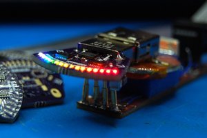
Edge-lit acrylic looks really cool, so I decided to add some right-angle LEDs to the front of my board and attach a piece of engraved acrylic to the front.
I liked the look of this one, but noticed a few issues:
For this version, I changed the position of the LEDs so they'd face downward and added some holes...
Read more »
Create an account to leave a comment. Already have an account? Log In.
Become a member to follow this project and never miss any updates

 Sarah Petkus
 Jarrett
 zakqwy
 mrpendent