Mastro Gippo
-
An idea to improve safety and security
10/28/2019 at 16:02 • 0 comments![]()
At this point I should really be wrapping up everything and start delivering the first units, but as I was preparing the front cover files for the factory I couldn't help adding a nice new feature.
---------- more ----------Basically, to encourage people to play with Prism, I separated the system in different blocks:
- any developer can easily write software for the Linux core, in many common languages like C++, PHP, LUA and Python, without any knowledge of electronics. Even if they don't want direct access to the internal system, they can easily develop on their own server using MQTT. There only risk here is to brick the Linux board, but it shouldn't be a problem as long as you don't try to flash a new firmware.
- Firmware developers can develop their own firmware for the internal STM32F103 that talks with the car, or for the Atmega328 on the front cover. For the STM32 there is a slight risk of damaging Prism, and a risk of damaging the electrical system if the current checks are disabled, but this shouldn't be a problem if the electrical system is built correctly (the breaker controlling that line should trip before any damage can be done).
- Electronic designers can cheaply build new front covers (5 pieces from JLCPCB are 20$) with additional electronics like NFC readers or custom displays, or experiment with creative new designs like a HAL9000 version with a LED ring, or a Supercar version with a horizontal LED strip playing the Larson scanner and the silhouette of K.I.T.T. etched on the copper layer.
As long as you play with the software only, there is no health risk - everything can be reprogrammed without even touching Prism.
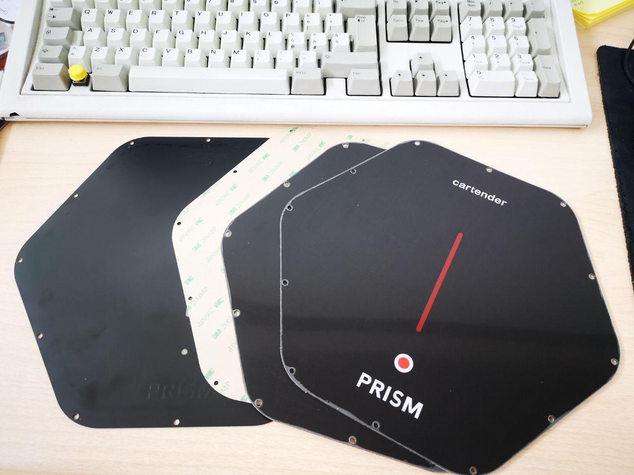
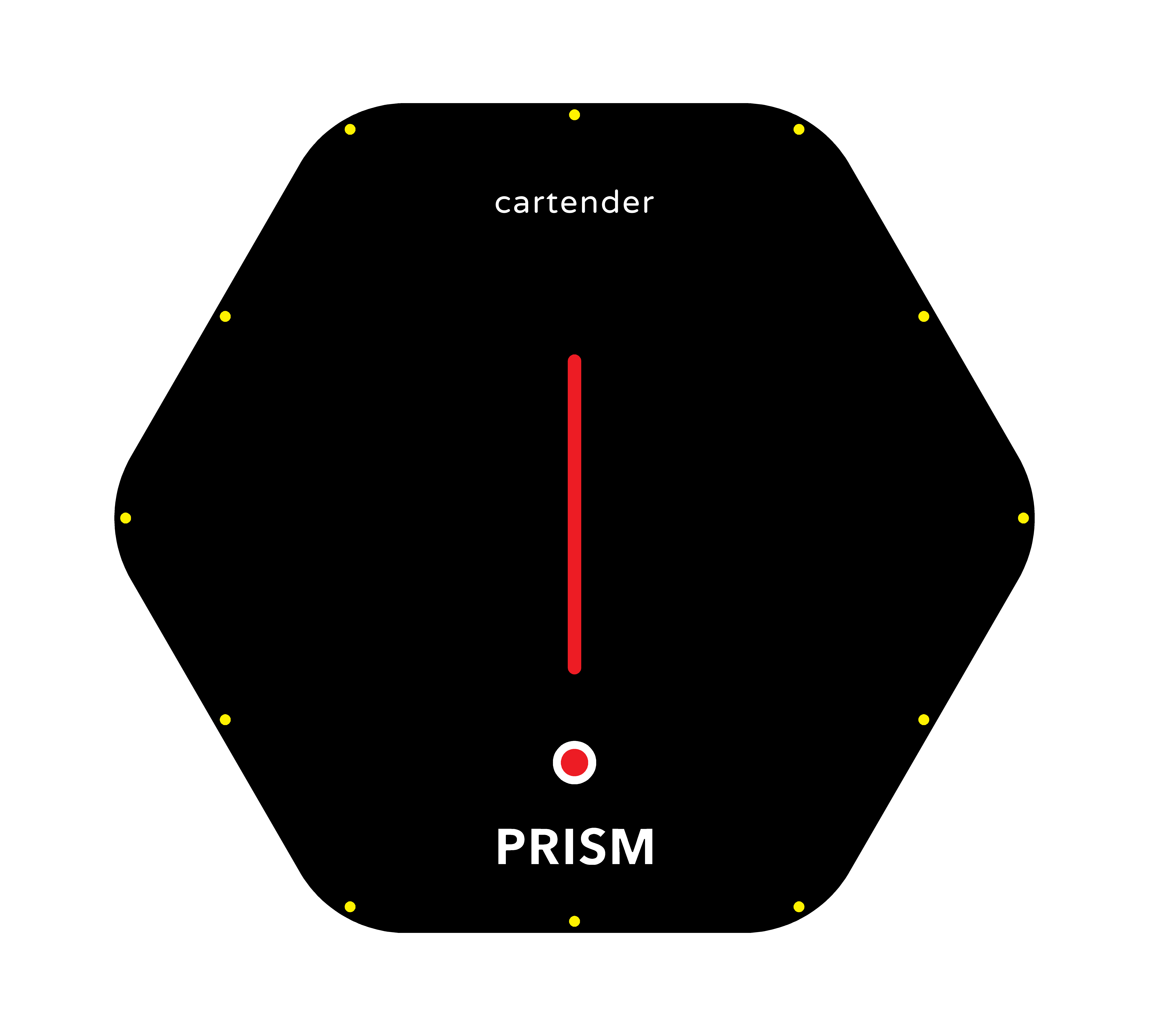
Only replacing the cover would be dangerous for the users, so to reduce this risk I added this tiny QRE1113 IR proximity sensor on the back:![]()
This will sound an alarm from the piezo when the cover is removed, to remind the user that there's still voltage inside the box, but other than improving safety it can be used to improve security too: we can send the user a notification, and even delete all keys and passwords if someone gets physical access to Prism! Then it's just a matter of securing the electrical box to make sure a potential thief/cracker can't remove power without being noticed. -
emove360 and Maker Faire Rome!
10/28/2019 at 15:16 • 0 comments![]()
It's been a crazy week, as I visited emove360 in Munich and the Rome Maker Faire netting 2000km in 5 days!
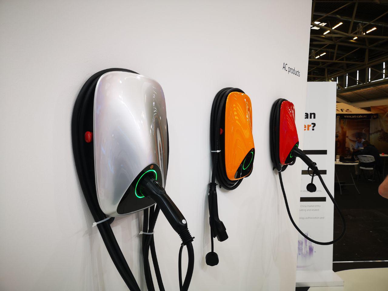
---------- more ----------First off was emove360, the biggest EV technical fair in europe. I've been visiting it every year and while it started with a wide range of exhibitors making motors, inverters, instruments, car conversion kits and more, it's starting to look more and more like a charging station fair. There were dozens of different new products, and I was astonished by the variety of designs and technologies on display. The Chinese are starting to catch up on the design front, but they're still mostly poor on communication and they still mostly use "standard" relays:
![]()
![]()
This one features a phase-swapping function, made with the 9 relays you can see near the energy meter. Below the energy meter, there is an RCD mounted face down with an easily accessible door on the bottom, so you can reset it without opening everything up. These are really nice features, too bad they put everything in a standard, ugly metal box:
![]()
My personal award for best design goes to the eBox; Michele argued that it looked too much like a water tap due to its stainless steel construction, but I think it's a really smart way to build a nice enclosure without breaking the bank and should be quite easy to assemble too:
![]()
It was weird finding Blaupunkt here. A long time ago they were huge in the car radio market, but then they completely disappeared (from my radar at least). I'm a bit disappointed, as their solution looked ugly and plasticky, and costed way too much for its quality and features.
![]()
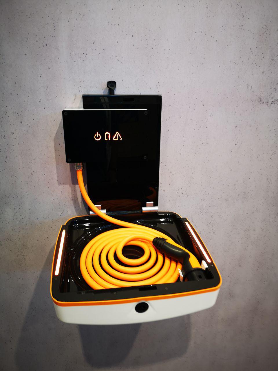
I also really liked these curvy designs; the white one has a replaceable cable that can be easily removed. I think they're a cable or connector company, as their solution must have been crazy to engineer and super expensive to make. They're saying that the advantage is that it's easy to upgrade, but I don't think connector standards will change anytime soon; that's a great idea on a semi-public station however, allowing to easily replace a worn up cable. On the second picture, some chinese products, looking nice but limited to single-phase charging.
![]()
![]()
This wins the award for weirdest design with a special mention for the "most probable charger to hurt you if you accidentally hit it with your head". It's not clear on the picture, but it's kind of V-shaped like an open book protruding from the wall:
![]()
Another contestant in the weird design category, this suitcase-like wall charger. There was no one at the stand to ask for more details, so I'll have to guess the "table" thing folds up and can be locked with the plastic key. Will you have to fold the cable up every time? What kind of problem does this solve, exactly? That's a mystery for next year:
![]()
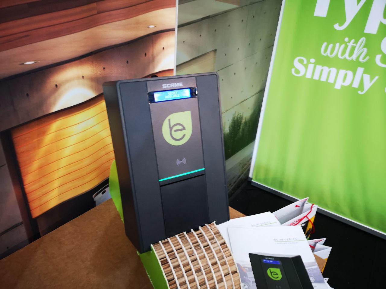
The only Italian charging station I found was SCAME's, that completely redesigned their product line. Their new products look great, maybe a bit "boxy". I'm still surprised by how many commercial devices still use 16x2 characters LCDs.
![]()
On the bad design category, this one wins the cake. I don't know why they're still selling them, as their newer version looks much better:
![]()
And to sum it up, the great wallbox stand (this is their picture, I didn't take one). The Copper is still one of the most beautiful products here, even if the front plastic cover is too thin and does not lay flat, making it look "cheap".
![]()
To sum it up, we counted 34 different designs. Of these:
- 21 looked good enough I'd buy one for my home
- 13 were from Chinese companies, 8 of them with good designs
- 27 had communication features, (some of them only had bluetooth or RS485)
- at least 12 had automatic load balancing (reducing the power to avoid tripping breakers), only 5 had an option to charge only from solar panels
- almost all of them had AC ground fault protection, but only 6 had DC protection too
- 8 implemented ISO 15118, a way to communicate with the car over power lines. I wanted to add this to Prism, but it was quite expensive and is mostly needed to authenticate the car for payments and we don't need that. It should be easy to add a module if needed as we have spare UARTs and USB host
Other than that, there were no Open Source products, no one had a knock sensor, or MQTT, or implemented car APIs, or have dual outputs, or could control Tesla wall chargers; only a few public charging poles (not wall mounted ones) had WiFi access point features. So I still feel pretty optimistic that my design will find its own space in the market!
Going back home we also met some engineers testing the new Porsche Taycan at Affi charging station:
![]()
The next day I was back on the road to Rome, and while driving to the Maker Faire I received a call from a journalist asking for an interview. Oddly enough, TV studios were right on my route so I ended up on national television :)
At the Maker Faire I met many amazing fellow makers, starting of course with Sexycyborg:
![]()
And, speaking of Hackaday prize, I also found the HapticGames stand:
![]()
And also had a lot of fun with the uECG team that night at the Hackaday meetup!
![]()
-
Security, OpenWRT and storage
10/08/2019 at 09:31 • 2 comments![]()
Tales of security woes over the years made me a bit paranoid about the various vulnerabilities I could expose my users to, so in the development of Prism I wanted to make everything as secure as possible without breaking the bank.
---------- more ----------The first goal is to avoid remote attacks as they’re way harder to detect than ones requiring physical access. We want to make especially sure that we avoid fleet-wide hacks and that compromising a single device will not make it easier to compromise the others. Today we will look at the first step in this direction: default passwords must be different among all devices as users are still not prone to changing them. This is usually done in the industry by calculating a unique password based on the basic devices characteristics, like the MAC address. This usually makes users feel safer and even less motivated to change the password (how may times have you taken pictures of the label under a friends router?). But once we find the algorithm behind the password generator by reversing the routers firmware, we can just sniff the MAC address and use the SSID to calculate the password for any vulnerable router. Device makers usually use this technique because it costs nothing, is very easy and provides some basic security; issuing truly unique passwords requires extra storage that has to be written before the device ships and needs to be persistent across updates. Routers usually have a specific partition for storing various calibration data; I experimented a bit with OpenWRT and found it quite hard to use that for storage and it sometimes wouldn’t survive recovery or direct flashing, but I don’t have a valid reason for why big manufacturers with big money and big development teams are not using it.
Well, turns out I have a nice STM32 on board. The easiest thing would be to read its serial number and hash it in some way to generate the passwords, and that would already be better than just using the publicly discoverable MAC address; but I wanted to go one step further as we have plenty of flash for my firmware and some storage. BOOT0 and Reset pins are connected to the Linux module for firmware updates, so I can use stm32flash to read and write its memory! And I’m not even enabling read protection since this is an open source project, so I can just use the tool to read the chunk of memory I need without bothering writing a custom serial command to fetch the data for me. Let’s try this!
I can generate a RSA key pair, a bunch of passwords for WiFi, root, user/admin/installer for the GUI, an update key, and store them all in a bunch of files:
#gen private
openssl genrsa -out ./$folder/$serial/id_rsa 2048
#save public key
openssl rsa -in ./$folder/$serial/id_rsa -outform PEM -pubout -out ./pub/$serial.pem

echo "$i" > ./$folder/$serial/serial

#wifi pass
echo `pwgen -Bcn 8 -1` > ./$folder/$serial/pw

[...]
I can then tar.gz it all, pad the file to 4k with dd and flash it at the end of the STM32 memory.
cd ./$folder/$serial/
tar -czvf ../$serial.tar.gz *
cd ../..

#check size
sz=`wc -c $folder/$serial.tar.gz | awk '{print $1}'`
if [ $sz -ge 4000 ]; then
	echo -e "\e[31mERROR!! $sz size for $serial\e[0m"
else
	# First, create a 128K file of all zeros:
	dd if=/dev/zero bs=1024 count=4 of=./$folder/$serial.bin
	# Then, write the BIN to the file without truncating the result:
	dd if=./$folder/$serial.tar.gz of=./$folder/$serial.bin conv=notrunc
fi
This way I can read it up on first boot from a clean image and setup everything!
stm32flash -R -i $reset -r key.bin -S $address:0x1000 /dev/ttyS1
tar -zxf key.bin

[...]

if [ -f "root_pass" ]; then
 #set root password
 pass=`cat root_pass`
 echo -e "$pass\n$pass" | passwd root
else
 logger -t loadkey "Error! No root pass file"
fi

[...]
And that is a great way to protect our users from “keygen” types of attack. But an attacker can still disassemble the device and read the STM32 flash! At this point we are only trying to protect the root password and the private key, as all the other passwords are printed on the manual and on a sticker. Protecting the root password (and other passwords if needed) is easy, as we can just store the pre-calculated hash:
#OpenWRT uses md5
mkpasswd -m md5 $password
but the id-rsa file with the private key needs to be readable! So as far as I know, the only way to do this other than using a TPM would be to gpg encrypt the whole file to add a layer of security. Of course I would have to use the same key for all the products due to the aforementioned limitations, and that means that an attacker just have to read the contents of an update or the flash of a device to discover that key. I could use an encryption password that is based on the MAC address or some other parameter, but that would only make it a bit harder as the attacker just has to reverse that.
I tried to implement all the best practices here, and I think I did quite well compared to big corporations. The biggest threat is, as always, physical access, but I have a big deterrent on my side: the charging station works at very high voltages, so the chances of an attacker messing with it are a bit lower; and if they play safe by removing power before touching it, that shouldn’t go unnoticed by the owner.
So what do you think? Can I take other measures to improve the password storage security, or am I already overthinking it? Let the Hackaday commenters wisdom decide! :)
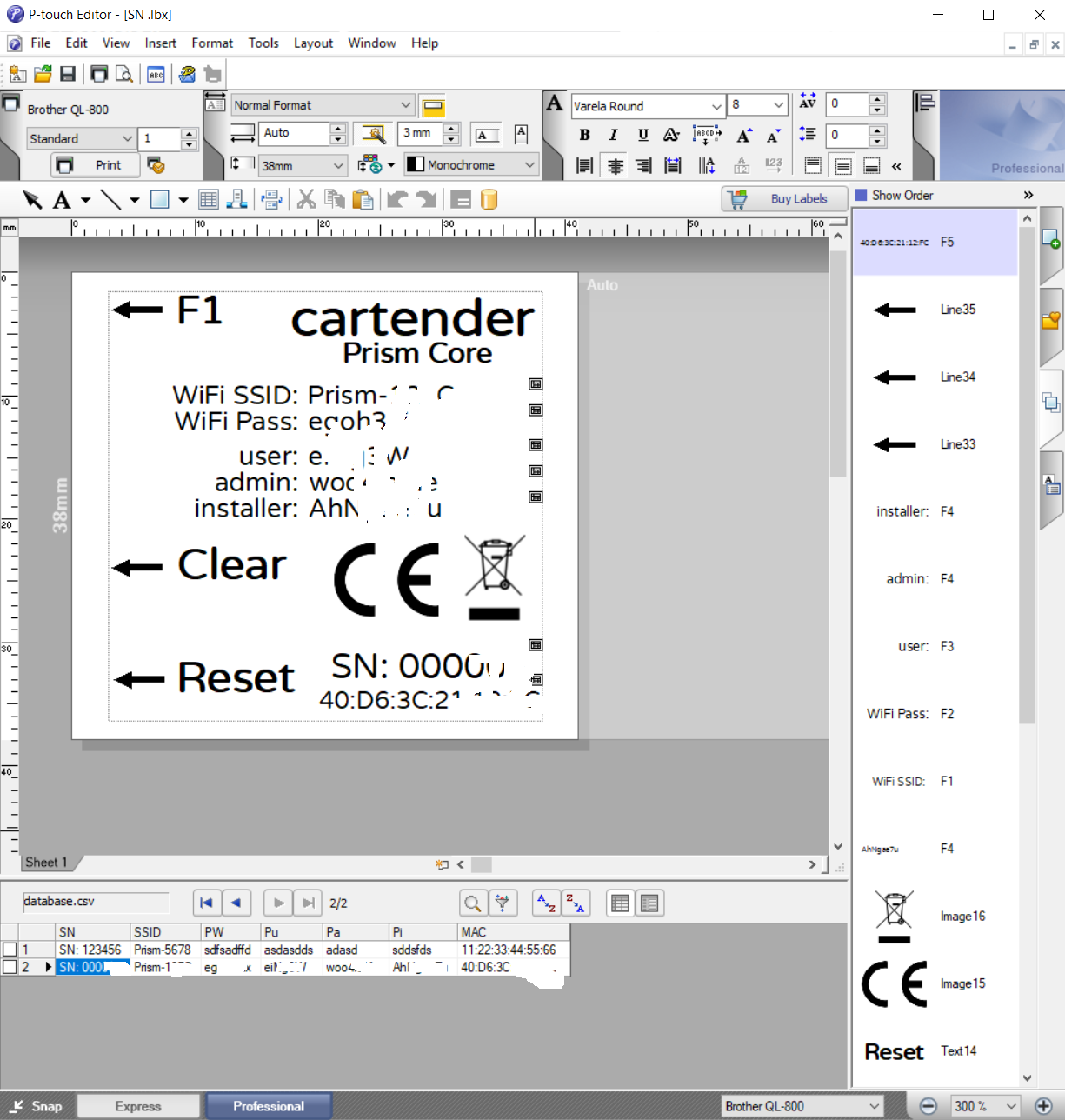
Bonus short post: I wanted to write a script to automate the printing of labels with passwords, serial numbers and MAC addresses so I purchased a Brother label printer instead of a Dymo because it was better compatible with Linux. I started with the best intentions, but it turns out the included software already allows importing data from a database, so I just had to throw all the data in a CSV and I was good to go in 20 minutes. The end. ¯\_(ツ)_/¯![]()
![]()
-
A quick recap
10/01/2019 at 12:43 • 0 comments![]()
Today is the deadline for the Hackaday Prize contest, and that's a great chance to write a recap article about Prism.
---------- more ----------Before going on with the technicalities, you can read an overview of the reasoning behind the project, learn more about EV charging basics, and read a brief overview of some similar products. We tested or even purchased most of the competitor products over the years but were not satisfied with them for one reason or another. So we decided to build Prism with every features we always wanted, and make it open so everyone could implement their own.
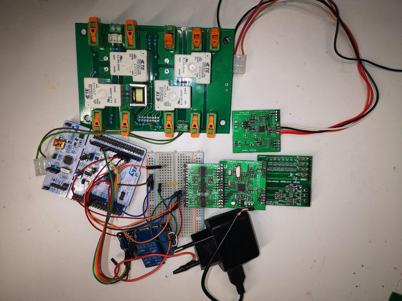
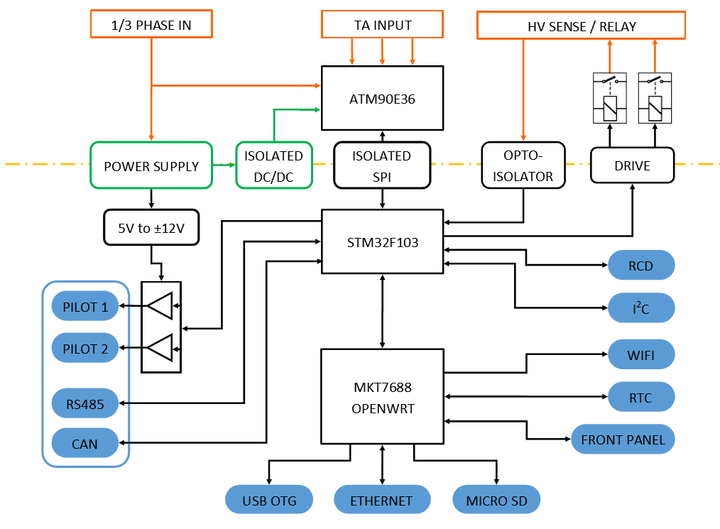
![]() It all started with some prototyping: I built a test board to talk to the car and a relay board to switch high voltage (Sources here and here). I went on testing another important part of the system, the power measurement module, that is based on a super cool Microchip ATM90E36 that does all the heavy lifting. I designed boards (HV in and ATM90, 12ch isolator) to test this part, reverse engineered Atmel/Microchip's own software, and wrote an open alternative (firmware here) to make it easy for anyone to develop software for this IC.
It all started with some prototyping: I built a test board to talk to the car and a relay board to switch high voltage (Sources here and here). I went on testing another important part of the system, the power measurement module, that is based on a super cool Microchip ATM90E36 that does all the heavy lifting. I designed boards (HV in and ATM90, 12ch isolator) to test this part, reverse engineered Atmel/Microchip's own software, and wrote an open alternative (firmware here) to make it easy for anyone to develop software for this IC.![]()
I then had to decide how to add intelligence and connectivity to the project. After long searches and lots of testing, I went back in time to the good old Linksys WRT54GL days and decided to use a routerboard module as the brain of the device. Using OpenWRT makes everything easier especially on the connectivity front, and the distro is very light weight, running on minimal hardware with a small power consumption. Adding an RTC to the module I discovered a bug in the kernel drivers and proposed a patch. What an adventure for a humble hardware dev messing with low level Linux!
With everything lined up and working, it's time to think about integration. Power management is usually pretty straightforward, but for this project it proved to be a bit of a headache as I needed various voltages. It was also time to update my Eagle library, since I've designed footprints and symbols for many hard to find parts while developing this project.
![]()
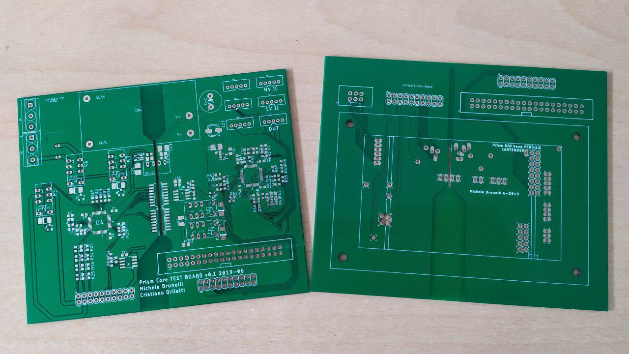
Trying to fit all the electronics inside a universal 3-DIN box proved a challenge. I wanted to use this enclosure as it's a proven standard and would make it easy to fit all the hardware anywhere, making the electronics independent from the outer enclosure. All the components will finally fit into four separate boards that are themselves modular, so it would be pretty easy to fit other linux modules replacing and modifying only the design of that board. Both Firmware and Hardware are open source of course; instead of releasing only gerbers we're publishing all the files so it's easier to modify them. The new version will be available soon, as we recently assembled a few boards and we're working hard testing them and ironing out the last few bugs. [Spoiler] I ditched the vertical boards and made a three boards stack, with standard and cheap pin strips to join them:
![]()
Getting ready to manufacture the boards we needed a fast and reliable way to test them so I asked Michele, our new intern, to design a nail bed. That would also allow him to get up to speed with the inner working of the project, but it turned out to be a quite spectacular fail. If anyone wants to help us on this part, sources are available here! :)
![]()
In the meantime, we were going crazy trying to find a viable and cheap solution for the exterior enclosure. We had to surrender to an expensive plastic mold, but not without a fight. I released the sources of an early prototype with potential for DIY experimentation. You can find the final enclosure CAD files here, to design add-ons or 3D print it (I wouldn't recommend that though, it has to be really strong to support the weight of the cable and auto-extinguish in case of fire).
![]()
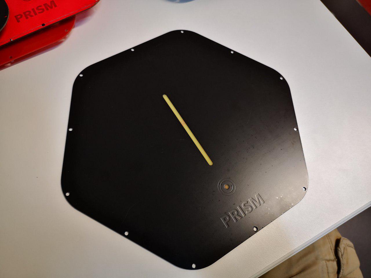
The design of this enclosure gave me the chance to experiment with an interesting concept for the front cover. I used a PCB for this part, as it's very strong and durable, can host electronics, is semi-transparent for LEDs and looks really nice. This raised a few concerns, but with the help of experts we found a solution that satisfied all safety requirements; I still have to test it due to some problems with the manufacturer though. Since this part is isolated from the high voltage stuff, this is a great gateway to encourage people to experiment! As sources are available, it's very easy for makers to customize this part. It's based on an Atmega328 so it can be programmed with the Arduino framework, with a piezo speaker to sense knocks and play sounds, a touch button and seven RGB LEDs. But I'd love to see someone develop some entirely different designs like a HAL9000 version with a LED ring, or a Supercar version with a horizontal LED strip playing the Larson scanner and the silhouette of K.I.T.T. etched on the copper layer!
Since a big goal for this project is to have people hacking it, safety has been an important driver for many design decisions so we only used certified industrial components for the final wiring and greatly oversized contactors to prevent fires. We also added a Residual Current Monitor (or GFCI) that detects both AC and DC leakage, since we're charging a >400V battery, that allows users to avoid installing an expensive external type B RCD . Being curious about how this worked, we disassembled and studied it while testing for standards compliance, and we discovered it works as a fluxgate magnetometer!
![]()
And as a final touch, we were finally able to reach one of the most important goals we set at the beginning of this project: charging a car with only free and clean solar energy. Playing with MQTT gave me a chance to implement some more frivolous functionality, like associating user input events to actions like remotely setting the charging limit through the car APIs (code here):
And finally, we started writing down some documentation both for the hardware and the software parts.
It's been quite a journey, and we still have to fight the final bosses: manufacturing the first batch and selling it. I'm pretty confident for the manufacturing part, as we got some samples of the new boards and they're looking good, and everything else is pretty much sorted out. About the commercial part, I trust my partners: we got a lot of interest from everyone we showed the project to. I've been working in the electric car industry for more than a decade, my partner ran his historic family car dealership for a long time and the third partner runs a successful renewable energy business so we already have contacts with many potential customers, some already lined up to get the first Prisms manufactured.
The price of the basic Prism is 950€ v.a.t. included, a bit less than the closest competitor but with more features out of the box and the obvious advantage of being completely open. There are also government incentives in Italy (our primary market for the first batch) that refund 50% of the expenses to people installing charging stations. The combination of price and features is quite attractive for residential customers and businesses owners to provide EV charging for employees and customers: when charging with solar energy, they can recover the full cost of Prism and its installation in less than 9 months, or half of that with government incentives! And that's not including the pleasure of travelling for free and producing no pollution thanks to the sun.
I won't dig too much in the details, but at that price we should recover the development costs and start turning a profit at around 170 sales. Bulk discounts for distributors or big installations would bring that number to about 260 units, but that would also mean we'd be selling more of them anyways. This is not including consulting services for customization, e.g. we have a potential customer for 40 units that requires some development to integrate Prism with his accounting software.
We're quite optimistic for the future and we hope to attract many nerds and makers like us that will join our project to make it great! After all we already are the biggest customers for electric cars, and owning one inevitably makes you want to experiment with it :)
Despite writing all the project logs from my point of view, this has been an incredible team effort. I'd like to thank all the amazing friends that helped make this project great. In order of "appearance":
- My parents, and especially my dad for teaching me all about electronics and passing on his passion
- Alberto, for being a great business partner and helping with the business and management:
![]()
- Anna, for designing and 3D modeling the gorgeous concepts:
![]()
- Stefano, for joining us in our business adventure and providing unique insights with his experience in renewable energy systems
- Michele helped modeling 3D parts and designing the cover and the testing jig:
![]()
- Giovanni made the Linux implementation a breeze thanks to his great experience in the field
- Paolo designed the gorgeous web frontend to manage Prism:
![]()
- Riccardo, for his amazing videomaking and photography skills
![]()
- And finally all the suppliers that worked with us to bring this project to light and made an extra effort to help us getting started.
Thanks!
-
OpenEnergyMonitor, Node-Red, MQTT
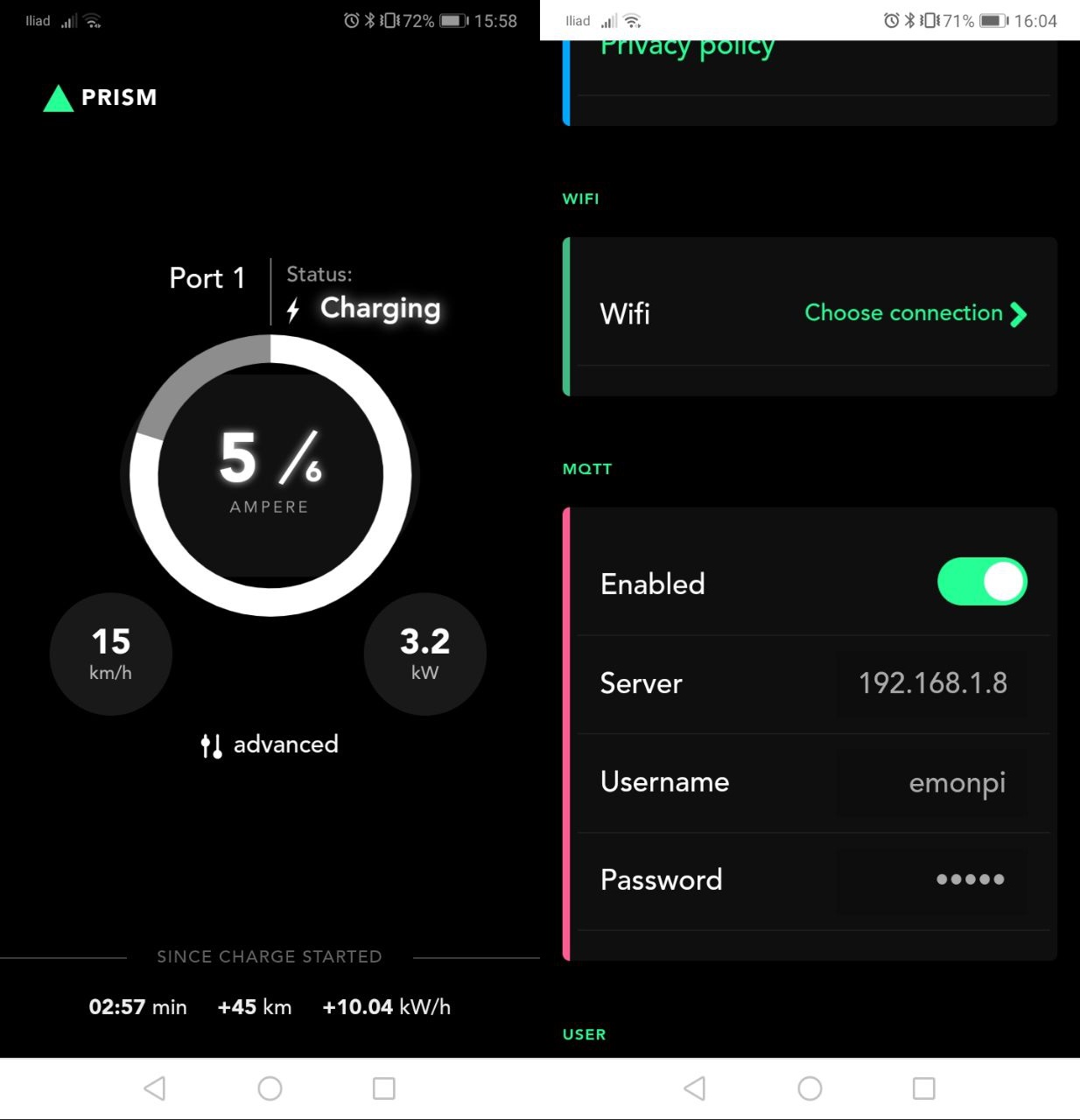
09/30/2019 at 18:43 • 0 comments![]()
All that effort to build a connected charging station brought its first victory as we were finally able to regulate charging based on the solar energy available. Since we had issues with our solar installation (panels are installed, but we're still waiting for the bureaucrats approval and meter installation to activate them), we went to a friends house to experiment with his installation.
---------- more ----------Talking to Prism is easy: all the basic stuff can be accessed and controlled via UBUS, OpenWRTs IPC system. From there, you can read and write charging parameters through any programming language, so we built a simple user interface with a backend in PHP to read data from the UBUS:
![]()
PHP for the backend, and LUA for our daemon translating the UBUS messages to MQTT to "simulate" an OpenEVSE to take advantage of all the software already developed for the OpenEnergyMonitor. Everything is well described in the OpenEVSE official documentation, and we're implementing these MQTT messages:
prism/amp Measured current in milliamps
prism/wh Calculated wh for the current session
prism/pilot Pilot current in Amps (6-80)
prism/state EVSE State (1–Ready, 2-Connected, 3-Charging, 4-Error)
Additionally, Prism will send events from the User Interface if no other action is associated with them:
prism/knock A numerical value for knock counts
prism/touch Touch button input
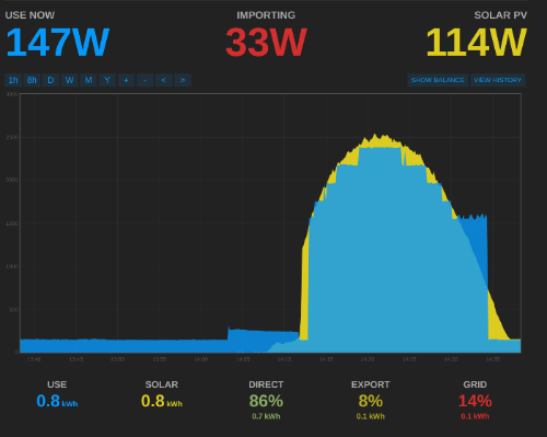
After setting up the whole system, we should be able to see a nice graph like this one, where the car charging power (blue) tries to follow the solar panels production (yellow):
![]()
The blue line is not curve because by standard charging current should only be controlled at 1A steps. This image taken from the OpenEVSE docs shows that behavior, but we're doing better as the Tesla can be linearly controlled as you can see in the first image of this post. We didn't have the chance to test if this is the same with other cars as we only had one day available for testing, but we'll test this further as soon as we get our solar system going.
But it doesn't stop here: there are many ways you can play with Prism, and Node Red makes it really easy to create custom scripts to automate boring stuff! Here's a short video demo where in just 5 minutes I setup a flow to intercept user knocks on the front cover to control the charging limit of a car:
And this was my first time with Node Red! Beside the 5 minutes setting up the demo, it only took me an evening to learn how to use it and implement stuff. I'm sure there are better ways to do it, but it works! I used hjesper's node-red-contrib-teslams, with a few modifications and improvements. If you don't have a Tesla, you can use the APIs for BMW, Renault, Nissan and more (just google "node-red [car manufacturer] api").
Another useful idea is to knock once to open the car charging port. This is as easy as explained in the video, but I wouldn't want my port to open when I'm far from home and someone touches Prism for whatever reason. A good solution for this is to implement geofencing to run the command only when the car is close to Prism (we have GPS data through the API). I'll leave this as an exercise for the reader, as it only applies to older cars (new ones have motorized charging ports with an integrated button).
I published the sources for the daemon here. It's an early demo and there's a lot to improve, but since they cover most of the basic features, that's a good starting point to develop your own stuff in LUA with MQTT - UBUS - serial connections.
-
Front cover protection and dealing with suppliers
09/29/2019 at 17:55 • 0 comments![]()
At the end of the front cover post I mentioned that we were working with a plastic sheet supplier to design an adhesive protector for the cover. I was pretty excited when I got the package today, but that excitement quickly turned into rage and frustration as soon as I opened it: the parts that should have been transparent are red instead.
---------- more ----------So instead of a technical overview of the solution, I will use this post to rant about suppliers and hopefully give you some hints to avoid making my same mistakes.
Dealing with suppliers is like getting arrested: Everything you say (but especially everything you don't say) will be used against you.
When buying custom products you have to interface with people working in companies making them and, especially in big companies, they are usually underqualified for their jobs (if you're lucky) or downright hate them (if you're not lucky), with a wide range of not giving a s**t in the middle.
It becomes clear pretty soon that the average person with an average job usually lacks the enthusiasm that an entrepreneur puts on its own creature, and that is perfectly understandable. However, sometimes it feels like they're actively trying to sabotage you, making every possible mistake, even against common sense. Here's a showreel of a few cases that happened to me:
Front cover
As I mentioned earlier in this post, I received the cover sticker samples with a red transparency (instead of a plain transparency). But why? Here's the email I wrote to the supplier (roughly translated):
Hello, please find the dimension in the attached cad file and the image to print on the plastic. I highlighted the holes in yellow, and the transparent parts in red.
![]()
Also note that the supplier knew that we had RGB LEDs there, because we showed them a prototype in our meeting. They went on vacation between our meeting and the samples production though, so it's possible they didn't remember. I'll take 30% of the blame here.
Chinese suppliers - clock drive
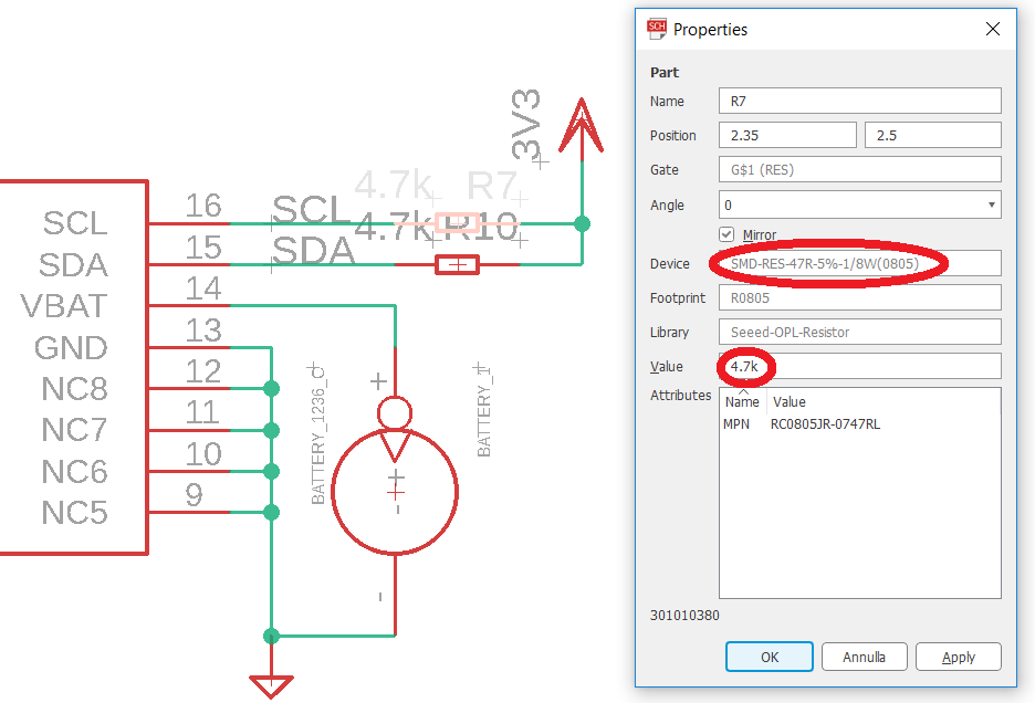
A few years ago I had a bunch of pilot circuits for mechanical clocks manufactured from a Chinese PCBA company. The project was really simple, instructions seemed very clear, I sent pictures and diagrams, and they still managed to mess everything up. First of all, I must admit a simple mistake: I used the Seeed OPL parts library because I originally intended to have my circuits built by them (I didn't). This library has hundreds of different resistor parts, each with its own value, instead of the normal RCL library I usually use that has a single resistor part where you just edit the value. Having edited the values of these parts, I thought I was good but I didn't notice how the "Device" field was reported in the BOM.
![]()
So the manufacturer wrote me:
- R2 is 47R or 4.7K ?it’s quite ambiguous in the BOM list. - R5 is 6.8K or 68K ?it’s quite ambiguous in the BOM list.
To which I replied:
- R2, R7, R10 are 4,7K - R5, R11 are 68K
AND OF COURSE THEY ASSEMBLED 47R AND 6.8K RESISTORS.
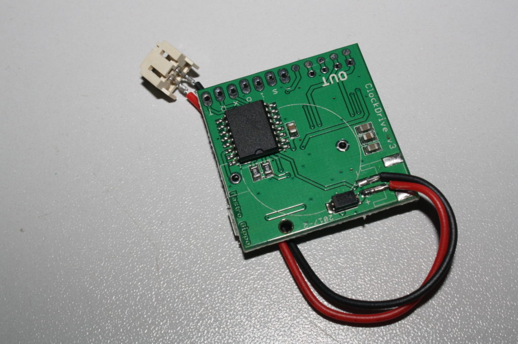
I should have noticed that when they sent me the pictures of the assembled boards, but I was too distracted by the f**k-up they did with the cable:
![]()
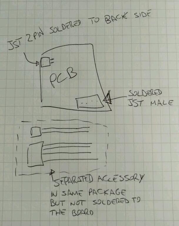
I may understand the confusion, as I also required matching cables and connectors, but why on earth would you do something like that? So I explained very well the problem, and they reworked the boards installing the connectors directly on the PCBs. I wrote:
There must be a misunderstanding. Both connectors must be soldered directly on the pcb without the cable! Then i need the mating connector plus some cable as an accessory separated from the board.
![]()
Pretty clear despite my bad handwriting, right? WRONG! Here's what I got: the 4 pins connectors with only 2 arbitrary cables inserted, and a bunch of useless female connectors that they no doubt recovered from the wrong PCBs:
![]()
But at least the connectors on the PCB were installed correctly, and new cables were pretty cheap from aliexpress.
So here's the lessons I learned from this:
- Find a supplier with a lot of patience
- Ask them to take a high res picture of the first PCB out of the production line before assembling all the others; promise to reply within an hour so you won't cause too much downtime for them. Then CHECK CAREFULLY every single component and solder joint.
- Make a prototype and send them pictures explaining the details. They will miss most of them, but it's worth trying. For this PCB I only had a rough prototype on a homemade board - JLCPCB didn't exist at that time so it was expensive to provide a real sample.
- Try to find a way to escrow the money. They will probably not accept that for small orders though.
- If at all possible, use assembly services like JLCPCB that is fully automated or Seeed. JLC didn't exist, and Seeed costed twice what the other company offered so I took the chance (and still came out ahead btw, if you don't count stress).
Of course, this applies for small runs; if you're manufacturing hundreds of parts you should at least ship a prototype to them, setup a testing jig at their factory, and travel there to oversee at least the first batch.
Chinese suppliers 2 - Prism
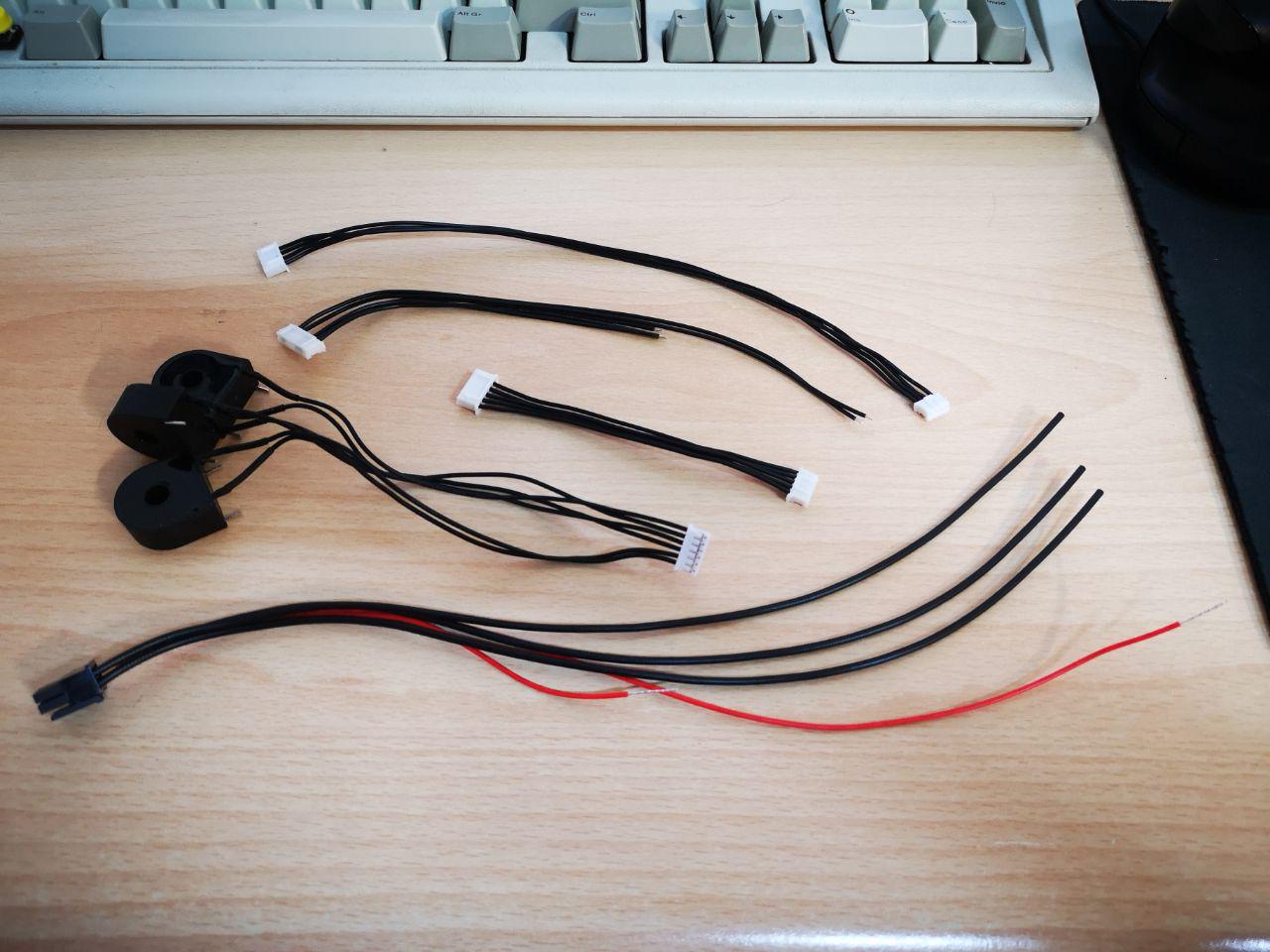
I started talking with the new, reputable OEM company well in advance this time. Before committing to PCBs, and as a way to test them, I had them make me 5 different cable samples. So I specified colors for each wire of the different cables. After a while, my contact with the factory told me that they only had black wires with 600V rating, so one of the cables would have three black wires. It was ok because they could be connected interchangeably. And then she said:
for other wire, if we have color, we will use color. if don't have much choice, we will use black, ok?
And that wasn't a problem either, because there were only two other wires in that cable rated at 300V, and they were interchangeable too, so I could easily deal with an all-black cable.
And of course, all the CABLES arrived with black WIRES, except the cable where I actually expected all black wires that instead got two red wires.
![]()
I also had them manufacture a small test run of boards, and that went (almost) great! So the lesson here is: Chinese companies will try to do everything you ask them, even if it's not their primary business. Instead of simply telling me that they didn't manufacture cables, they tried to make them anyway, with very poor results. Make sure you check their capabilities! I found another company making cables 15 minutes from home, and everything went perfectly, despite costing twice the Chinese. Another tip: if the price difference is not too big, always prefer local companies. The cables are a very small part of the total cost of the product, so that makes a lot of sense for me. On the other hand, assembling PCBs here is just not economically feasible.
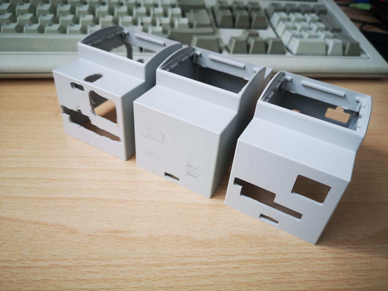
DIN box
In this company, the woman in charge of taking customer orders clearly states in every email that the final customer have to carefully check that she transcribed correctly what you write her, and if she made any mistakes that you don't spot you're fully responsible for that and will accept and pay the order as-is. And oh boy, did she make mistakes. We soon figured out the reason for that disclaimer: despite clearly stating our requirements and including her in every communication with the technical department, she always found ways to sneak in at least one or two mistakes on every document she prepared, almost as if it was on purpose. After the first ones we learnt our lesson and meticulously checked every single word she typed; this took quite a while, but in the end we got the product we needed. And don't get me started about the bulls**t bureaucracy and formality required by this particular company, that amounted to 53 emails exchanged just to get some samples.
I understand that we're a small customer, but this has been so frustrating and time consuming that I'm seriously considering other alternatives when I will scale production.
![]()
And while I talked well about the plastic manufacturer in the previous post, they too made a mistake while producing the first samples: molds are symmetrical and they didn't place reference pins, so they mounted one rotated 180°. Luckily this only meant that some non-important features were placed on the opposite side, and they immediately corrected the problem and printed more samples.
In hindsight, we've just been a bit unlucky but our diligent babysitting prevented at least the biggest mistakes, and that made us waste A LOT of time but thankfully not that much money. I guess that scaling up we'll need to get personnel just to babysit suppliers, and that's frustrating as I'd rather hire more engineers.
It's interesting how many processes are being standardized and automated and now require almost no human intervention, like the LCSC assembly service, that should leave you the responsibility of sending all the correct data in the format they expect in the first place, with an instant feedback previewing what they will manufacture to find any discrepancies before committing. That's the future; I guess I'll throw a party when the DIN box woman will be replaced by a small shell script.
-
Board testing: it's fun, they said
09/26/2019 at 11:59 • 0 comments![]()
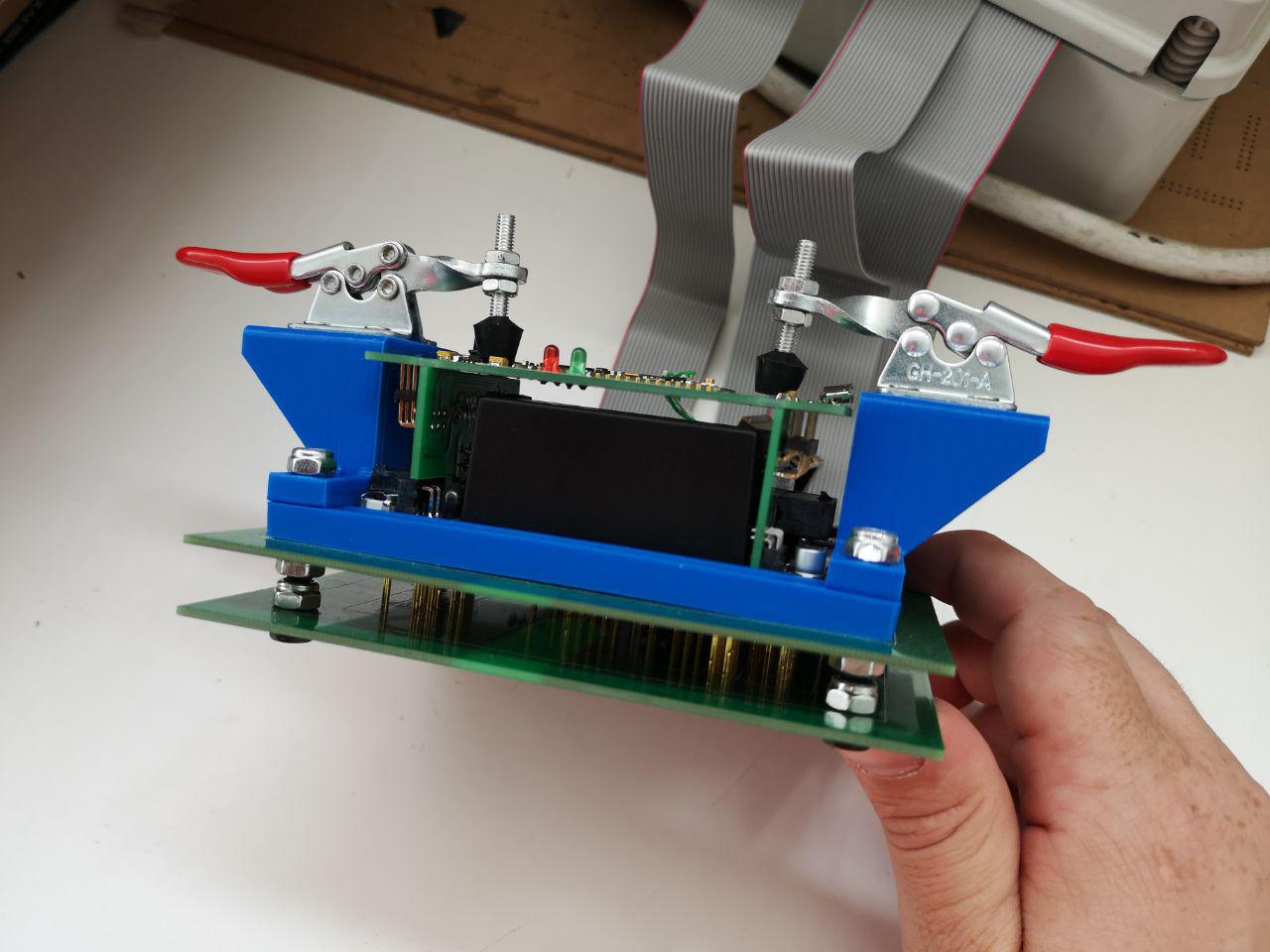
This post is written by my friend (and now colleague/intern :) ) [Michele], who worked on the test board. I assigned him this task as it's the best way to learn about the boards and get up to speed with the project. It also seemed a great way to test the really interesting Exclave project from [bunnie], but -spoiler alert- we'll have to wait for that.
After manufacturing the boards, we need to test them to make sure that the assembly house built them correctly. This is my first time designing a nail bed, however the task seems quite simple. I have to test the following:
- Short circuits
- Voltage levels from the various power supplies
- Current consumption
- Communication (RS485, I2C, SPI ...)
- Other signals to and from the board
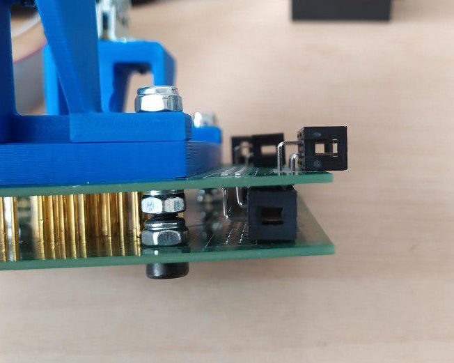
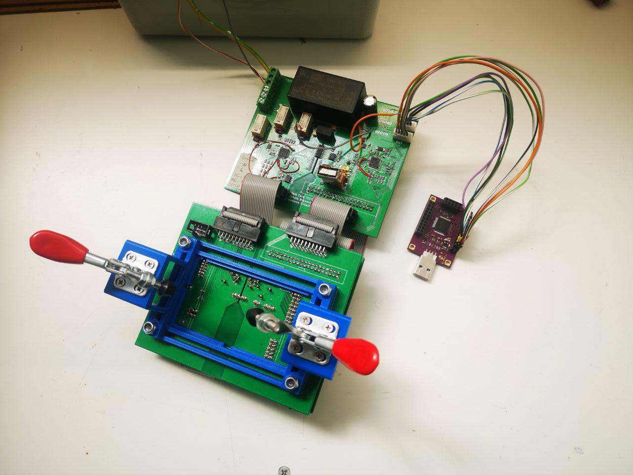
Being this my first time, Mastro Gippo explained me very well what he has in mind for this testing device. It will consist of two pieces: one double-stacked board with pogo pins and clamps to secure the device under test (DUT for short) and another board with all the logic and the supply to do the testing. The logic board will be divided in two parts, one for testing the high voltage side of the DUT, which is attached to the mains power, and another part for the low voltage side (12V max). All looked very clear to me, so let's get started!
---------- more ----------First thing first, the board design.
Using the DUT board file as template all I have to do is putting some holes under the test points and under the holes for the connectors and the pogo pins will be perfectly aligned. Some pads were put at weird angle to avoid overlaps, but this is not a problem.
![First pieces of the test equipment - board with pogo pins]()
Add some border, put some holes to secure the clamps that will hold the DUT, add connectors, route all signals and it's done.
Now get on with the next piece of the puzzle, the board with all the power supplies and the logic.
![]()
MCUs
The brain(s) of the testing equipment are two STM32F103C8. This was an easy choice, the chip has all it's needed and is used also in the DUT, so we have a lot of them at hand.
Power supplies
Another simple task. I used the same components and schematic we used for the DUT:
- IRM-20-5 - from 220V AC to 5V DC
- B0505S-1WR2 - isolated DC/DC to take the 5V from the low-voltage side to the high-voltage side
- 2x AP2112K - 3.3V for the two MCU, one for the high-voltage side and one for the low-voltage side
So far so good.
Voltage lines testing
To test the voltage lines all it's needed are a couple of voltage dividers to decrease the various voltages to under 3.3V, connect the signals to any analog pins and this is it.
Short-circuit and current measuring
I used some relays to switch the 5V and 220V lines that goes from the testing board to the DUT to power it up and two ACS71205B hall-effect current sensors.
First the short-circuit test is done powering the DUT from the 5V line with a 100ohm series resistor to limit the current and check for short circuits. After making sure we're good, the current consumption is measured first with 5V and then with 220V powering the DUT to see if it's within the normal range.
Isolation
The central part of the board provide the isolation between the two sides, the high voltage and the low voltage ones. As you can see under the main components of this part, the DC/DC isolated converter and the two SI8441 digital isolators, a slot in the pcb is needed to provide the right isolation. On the top and bottom part some space is left among the two ground planes for the same reason.
Other signals
All the remaining signals to test are routed directly to the two MCUs. For the low voltage side this required a lot of time to route all of them and this took me to mistake a couple of signals. Routing an analog signal to a digital-only pin is not a smart idea...
![]() A picture of me after connecting an analog signal to a digital-only pin
A picture of me after connecting an analog signal to a digital-only pinUnfortunately I noticed that only after soldering all the components and testing.
Boards assembling
![]() Test boards - logic and power supplies on the right one, pogo pins on the left
Test boards - logic and power supplies on the right one, pogo pins on the leftSoldering the pogo pins was a long and tedious, yet quite simple job. I've aligned the two boards like a sandwich, soldered 4 pogo pins at the right height and then use my professional pogo pins alignment tool as a base for soldering the other pins at the same height. After this set up, is only a matter on time and patience.
![]() Here is how to align pogo pins (like a pro)
Here is how to align pogo pins (like a pro)A small tip for you: if you designed the board for vertical connectors but have ordered only 90 degrees ones, the next photo will give you a painless solution.
![]() Mater artium necessitas
Mater artium necessitasWe used locking nuts and bolts to "calibrate" the distance between the two boards and to give robustness to the assembly.
To complete this board the only thing left was the structure for the clamps that hold the DUT in place. Thanks to my experience in 3D modeling and 3D printing I did this right at first try - bravo.
![]() Completed test board
Completed test boardThe other board was easier to solder: stencil, solder paste, hot air station, soldering iron and... voilà!
The real testing - a rough journey
With the boards ready it's time to see if everything's working.
- Power supplies - OK
- MCUs firmware uploading - OK
- Relays..... uhm, no clicks.
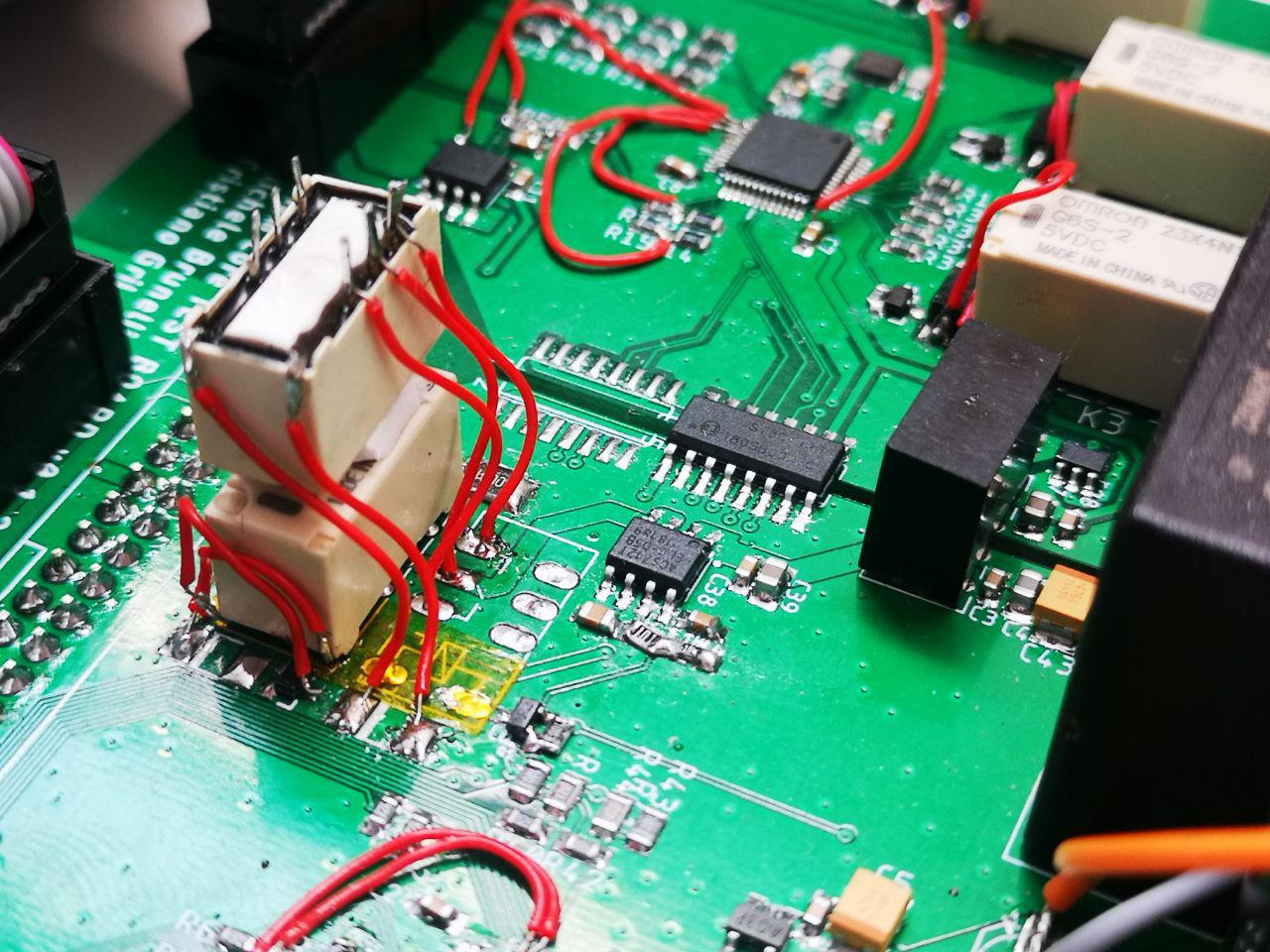
Relays
For some reason the relays weren't working. I checked all the signals twice, voltage is within range, but they're completely dead. Maybe I can try to reverse the coil connections.... and now it's working. Why? Checking the datasheet again, I found the reason for this unexpected behavior. I used the G6S-2 relays, can you spot the difference with the others?
![]() Relay's datasheet - can you find the differences?
Relay's datasheet - can you find the differences?If you're better than me at this type of game, you probably found what I've missed. All the relays have a top view footprint, but the relay that I used was the only one with the terminals represented from bottom view. Of course, that is because it's the only through hole part, but I didn't notice that when creating the footprint for the relays. Thank you, Omron. Thank you.
![]()
Hopeless, I took my best friend on this journey - the soldering iron - and re-wired all the relays.
![]()
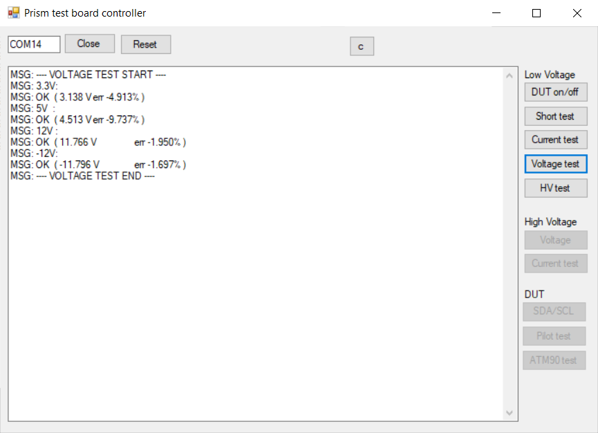
I tested all the relays again and wrote some firmware to check the DUT power lines voltages. Very well, now it's working. First task completed!
![]() Voltage test completed
Voltage test completedCurrent sensing
On with the current sensors. All that should be needed is to read a voltage level, do some math and it's done, right? The short circuit testing worked pretty well, but for some reason the current consumption measurements returned wrong values and were very inconsistent.
Luckily for me, Gippo quickly found the issue: turns out placing an electromagnetic relay near an hall-effect current sensor is not a good idea. So I moved the relay away by flipping it and sticking it on top of the other relay.
![]() That's it for the low voltage side of the board. I kept going with the high voltage side, at least current consumption need to be measured.
That's it for the low voltage side of the board. I kept going with the high voltage side, at least current consumption need to be measured.Strip some cables, connect the board to the mains power and check the value read from the current sensor... And it reads wrong values again when the relays closed. But the relays were far from the sensor, what could it be?
It was a problem with the unregulated 5V DC-DC converter supplying the board. The ACS71205B current sensor does not have an internal reference, and having 50 to 200 mV drops on the 5V supply when turning on the relays lead to completely wrong current measurements.
As last hope I've tried to supply the current sensor via the regulated 3.3V line, despite the datasheet recommending a supply voltage between 4.5V and 5.5V. After doing some measurements with the sensor powered by 3.3V supply and plotting the values, the results were good but not linear anymore. The only ways left to solve this problem were to add a regulated 5V power supply or connect the 5V line to an analog pin of the STM32 to correct for these changes on the supply voltage. Having exceeded the error count for this board, I will fix this on the next version of the board.
![]()
![]()
![]()
Giving up (..at least for now..)
Being the deadline for the testing device missed, I have to surrender and test the boards manually. At least the pogo pins board give me a handy place to wire everything to the DUT.
But this is not the end. I am a proud person, and soon or later I will win this battle. The next version of the board is almost ready and all the (known) error are fixed.
You can find all the latest sources here!
Stay tuned!
-
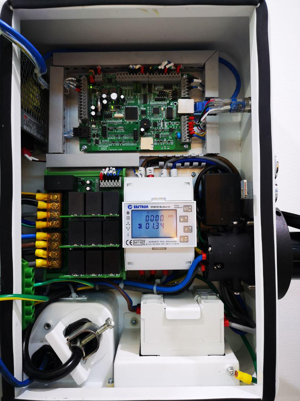
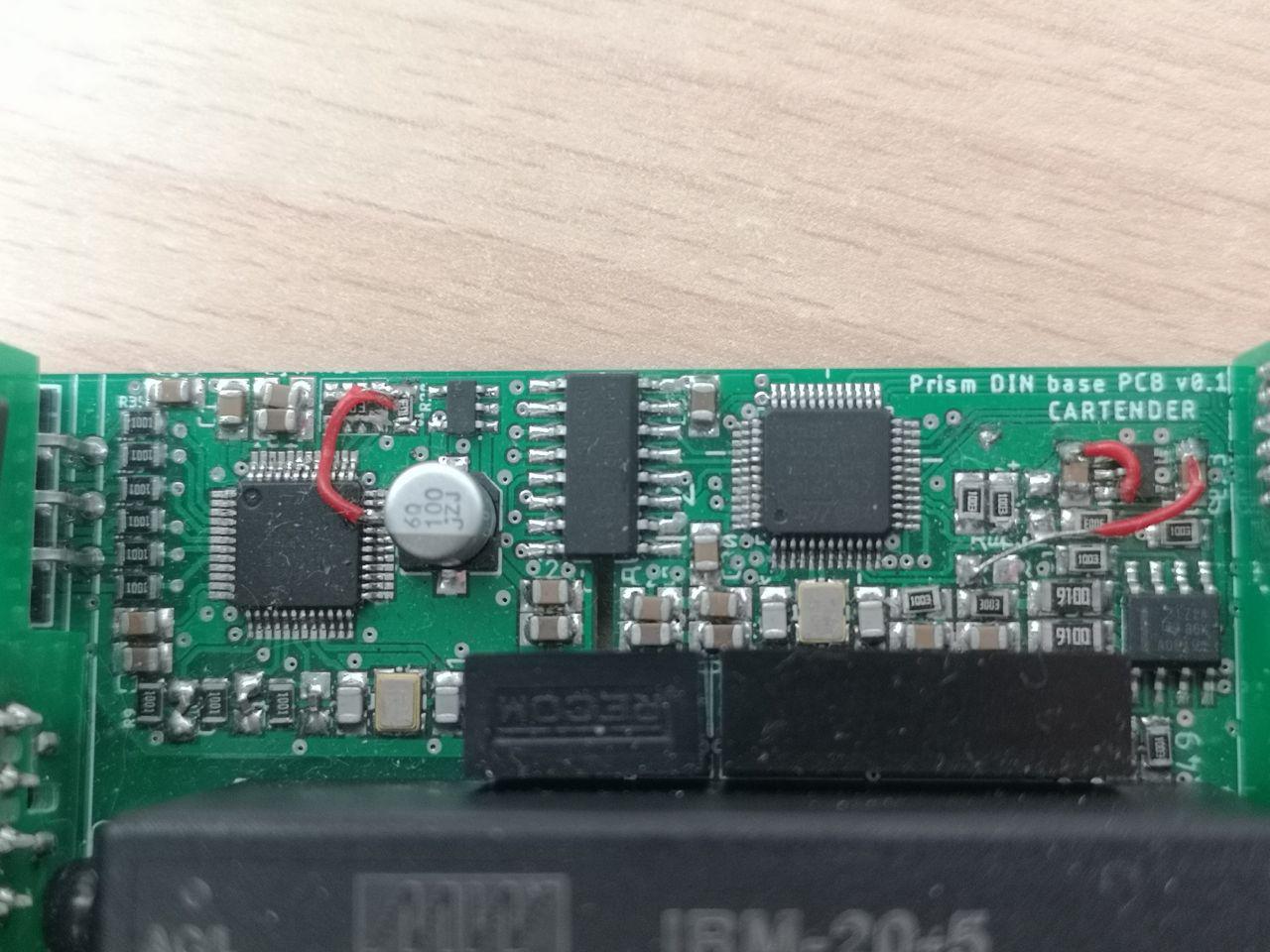
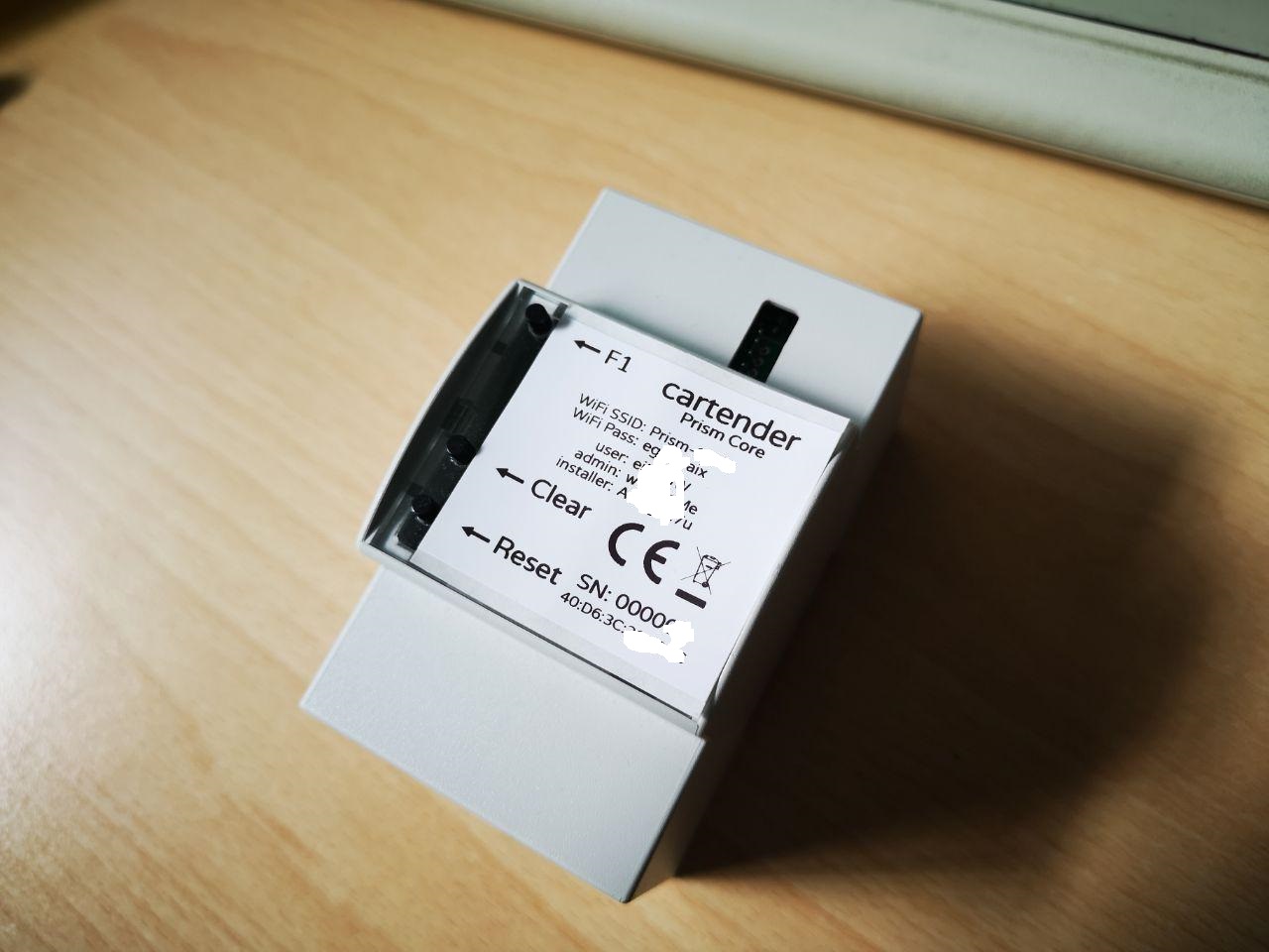
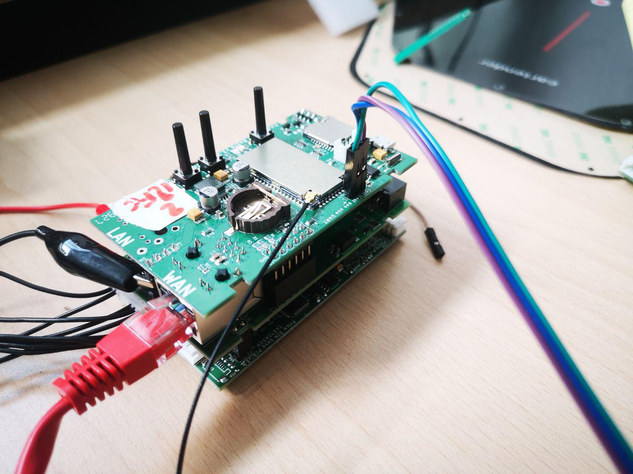
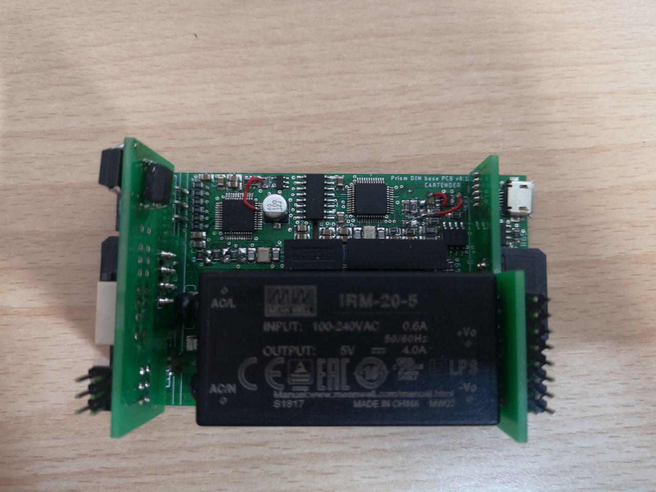
Prism Core boards
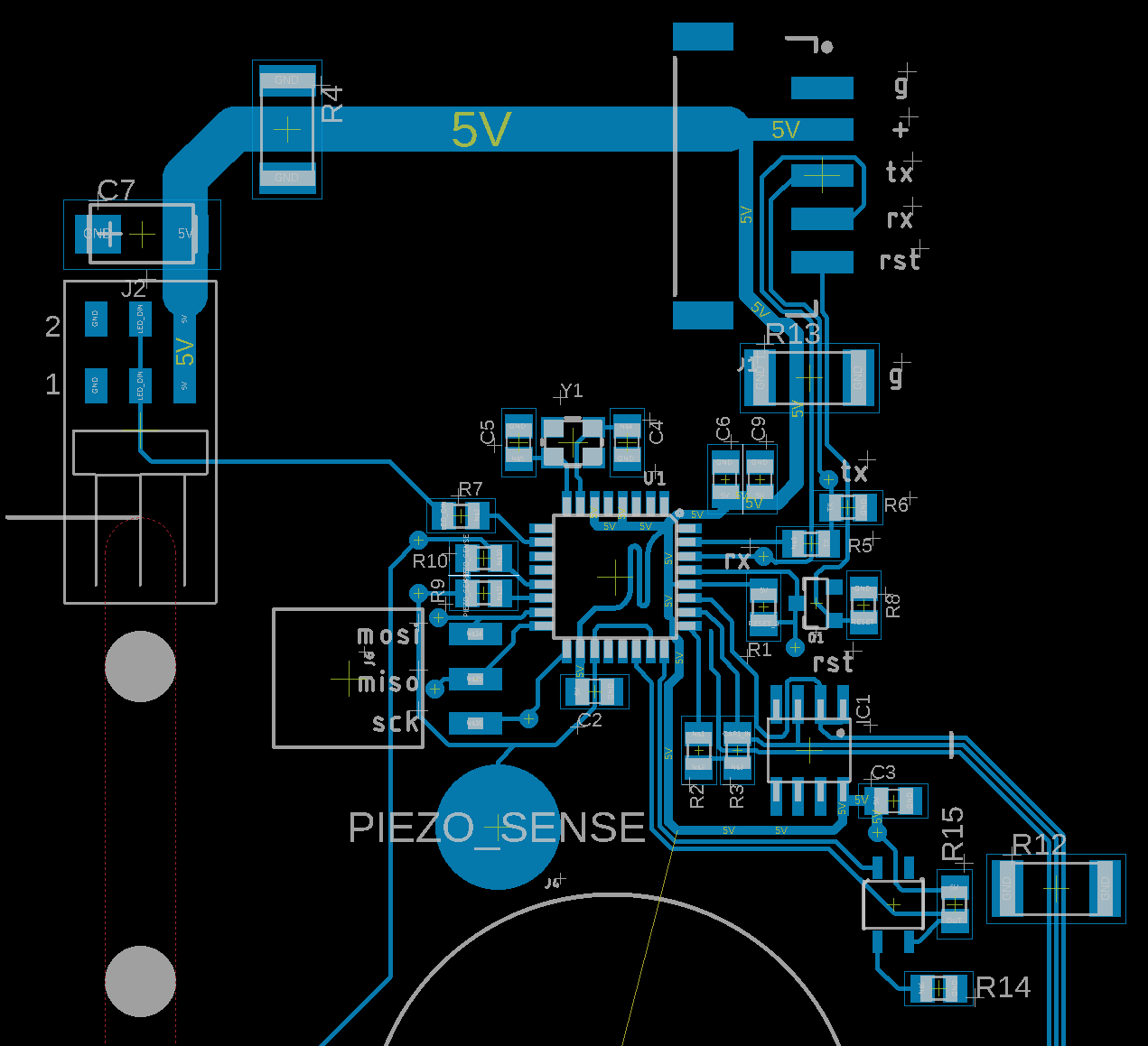
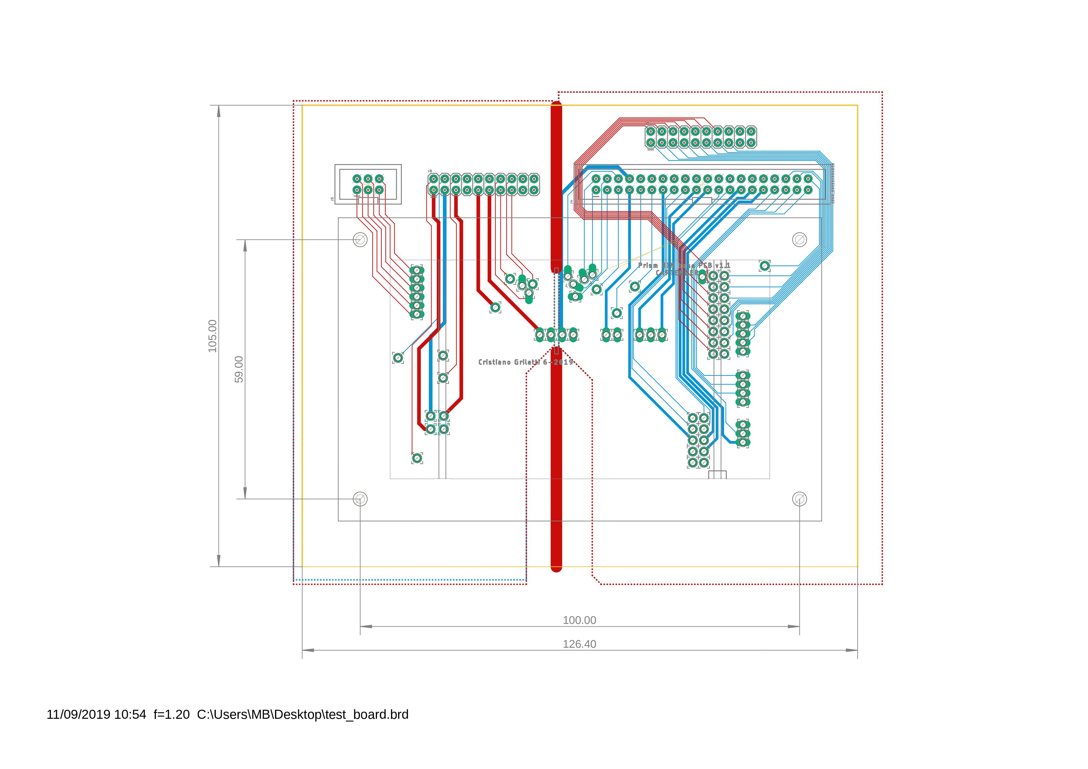
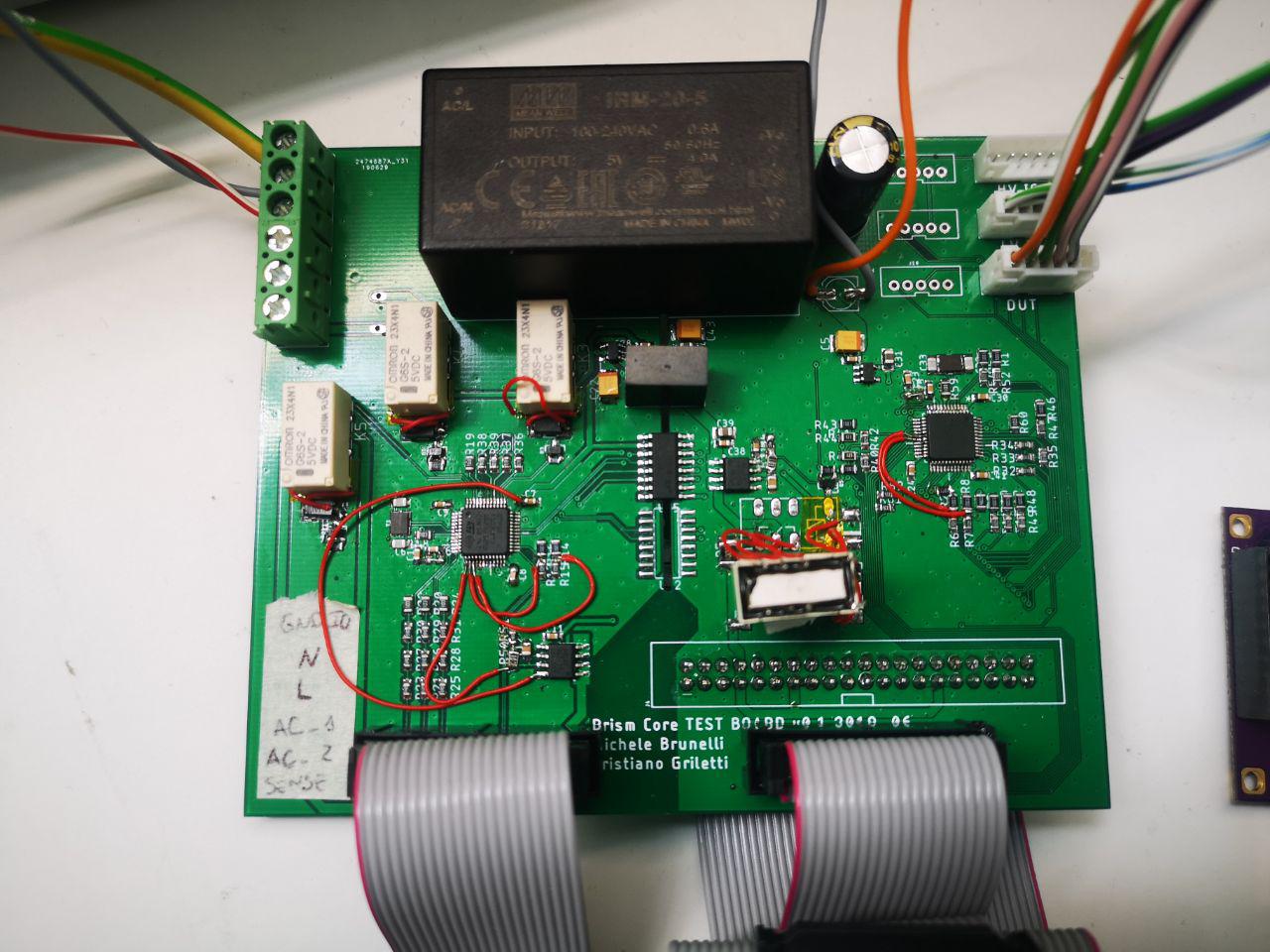
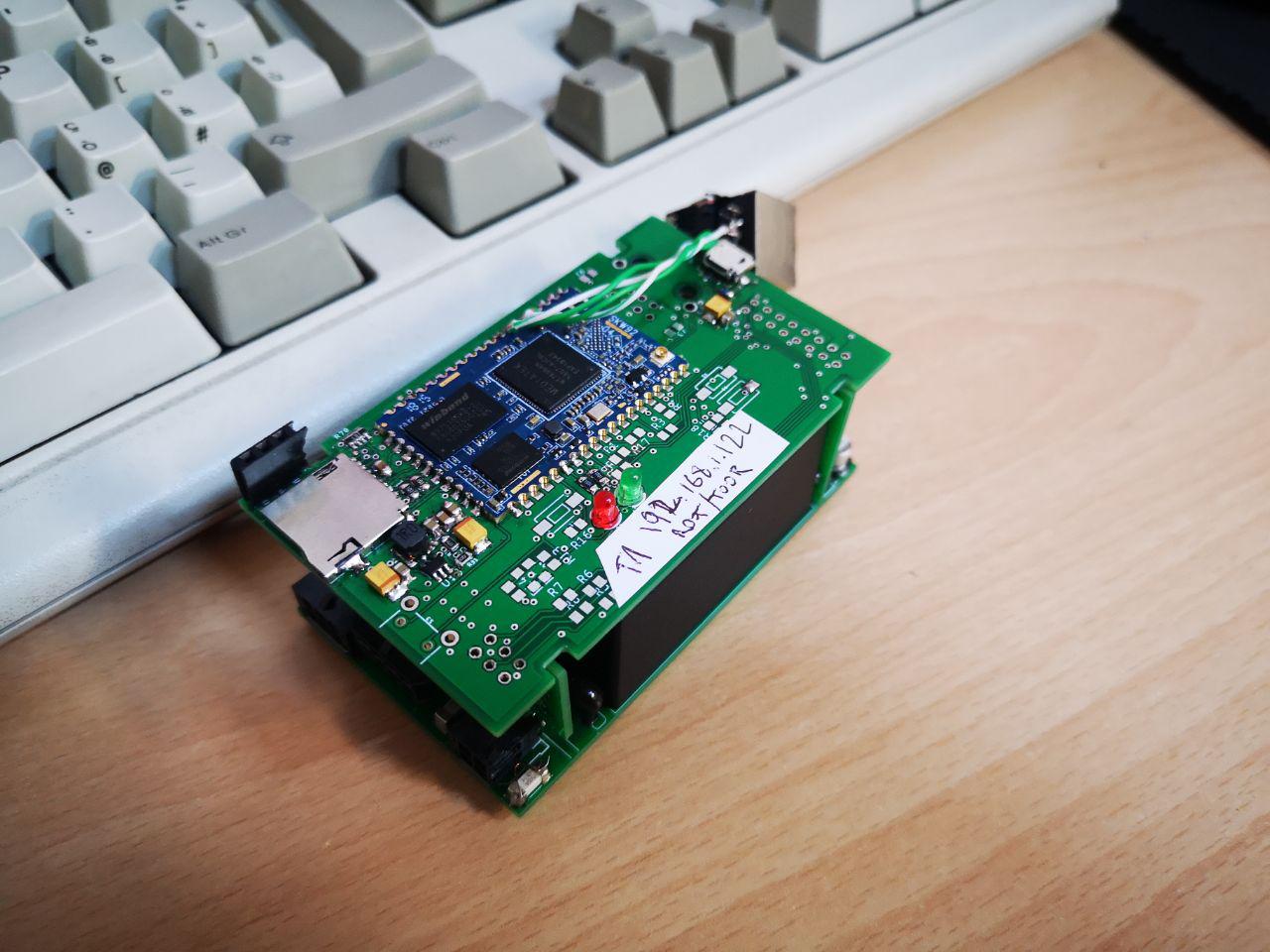
09/25/2019 at 19:06 • 0 comments![]() Now that I tested and improved the proof of concepts for power, energy measurement, control and car interfacing, I can merge everything in a single block that fits in a nice box. As discussed in the enclosure post, I choose to use a 3DIN standard box so I looked around for options.---------- more ----------
Now that I tested and improved the proof of concepts for power, energy measurement, control and car interfacing, I can merge everything in a single block that fits in a nice box. As discussed in the enclosure post, I choose to use a 3DIN standard box so I looked around for options.---------- more ----------I was pretty lucky to find a reputable manufacturer 5 minutes from home, and decided to test their 3MXTSC box:
![]() Documentation for this product is very good, and it was pretty easy to model the PCB outlines after their technical docs. Having a lot of stuff going on, it was pretty clear that I had to spread all the electronics on at least two PCBs. How do we split functionality? The constraints of this problem are to keep connections to a minimum and put the high voltage stuff all together with good isolation.
Documentation for this product is very good, and it was pretty easy to model the PCB outlines after their technical docs. Having a lot of stuff going on, it was pretty clear that I had to spread all the electronics on at least two PCBs. How do we split functionality? The constraints of this problem are to keep connections to a minimum and put the high voltage stuff all together with good isolation.
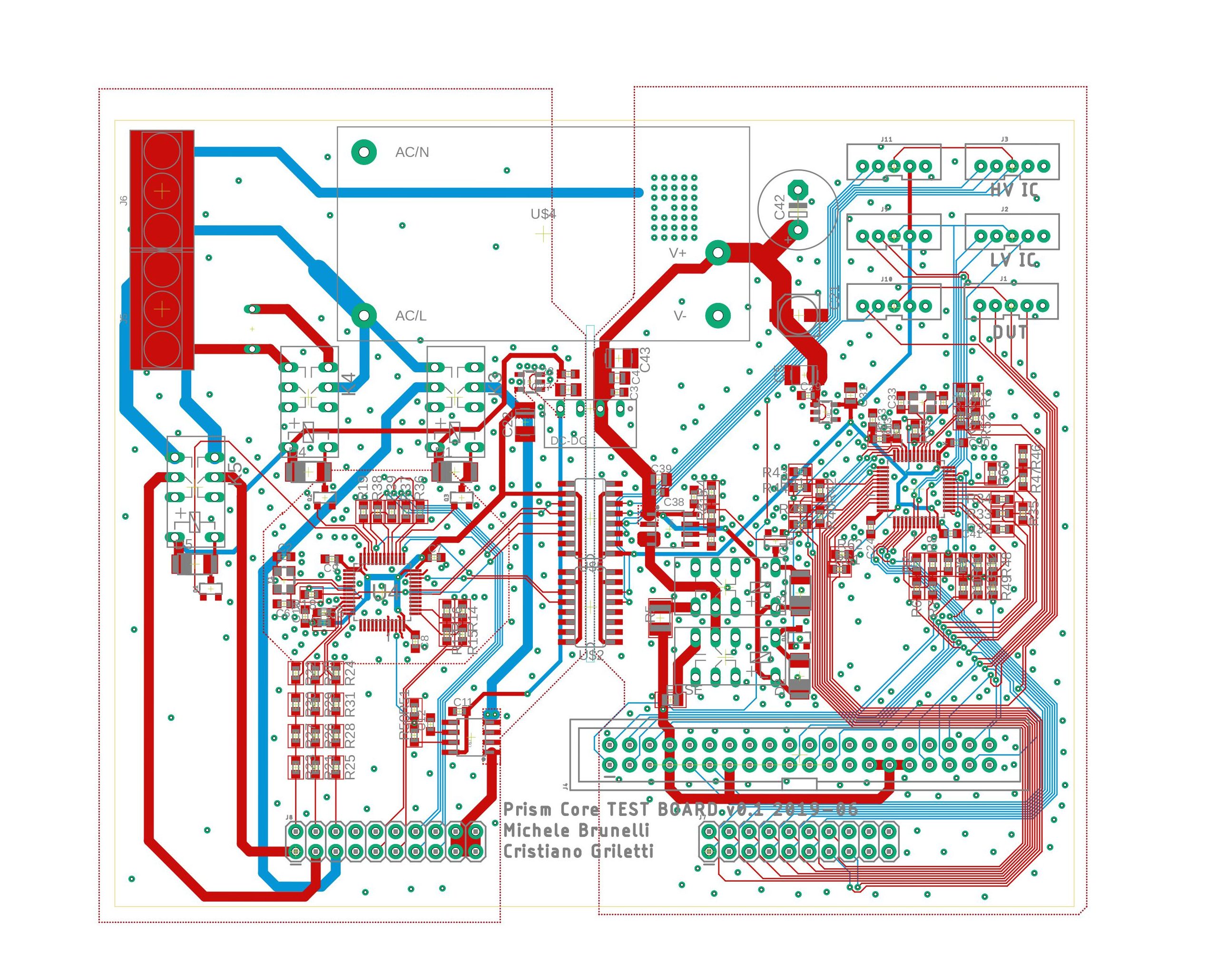
![]() It's clear that a good option would be to separate everything along the yellow line, leaving the High Voltage stuff on the bottom board and putting everything else on the top one. However, while designing this board I found that there was a lot of space left so I started including more and more stuff, like the STM32 and driving circuitry for the Pilot signal, so I ended up placing almost everything there:
It's clear that a good option would be to separate everything along the yellow line, leaving the High Voltage stuff on the bottom board and putting everything else on the top one. However, while designing this board I found that there was a lot of space left so I started including more and more stuff, like the STM32 and driving circuitry for the Pilot signal, so I ended up placing almost everything there:
![]()
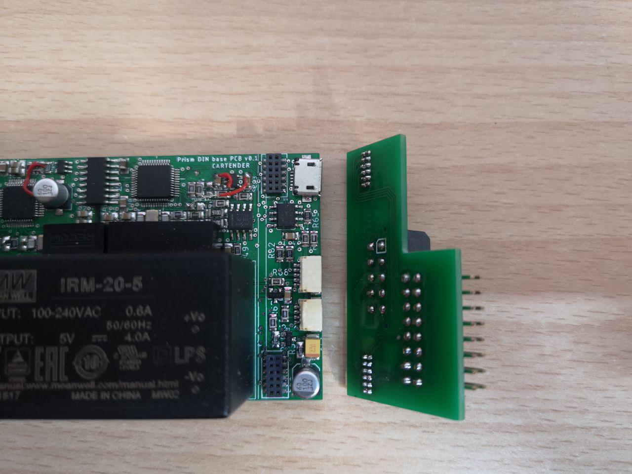
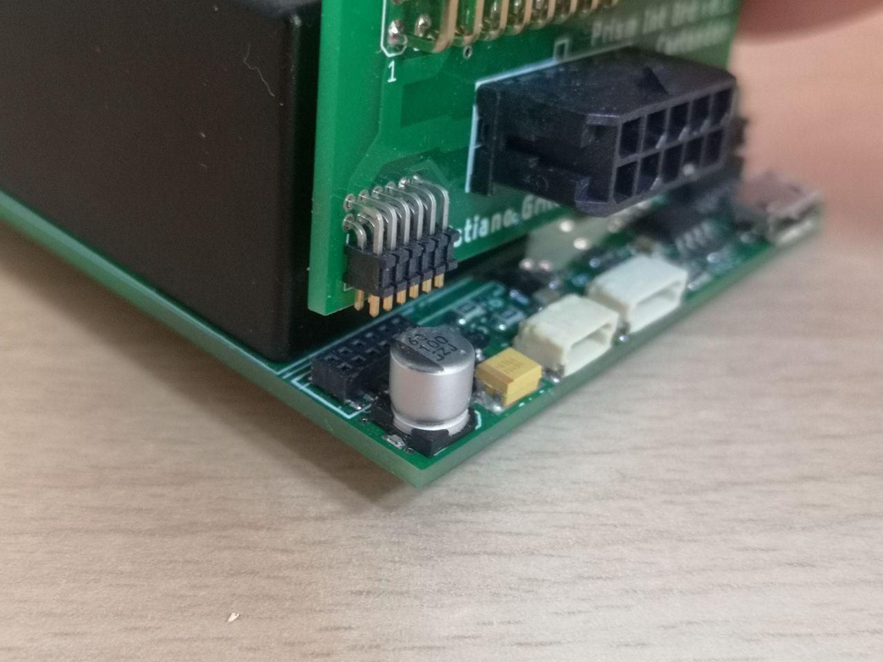
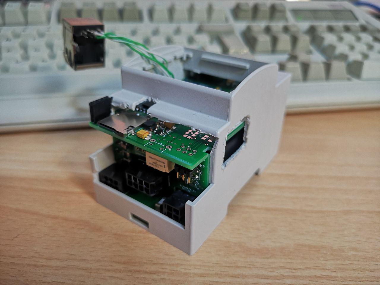
I also had to think of a way to connect the boards together. I've seen many manufacturers using flat cables or big connectors for similar applications in DIN boxes, but if you read the front cover article you'll know that I love using PCBs in weird ways. So I decided to use two vertical PCBs as "bridges" to connect the boards sides, as they fit perfectly in the DIN box slots:
![]()
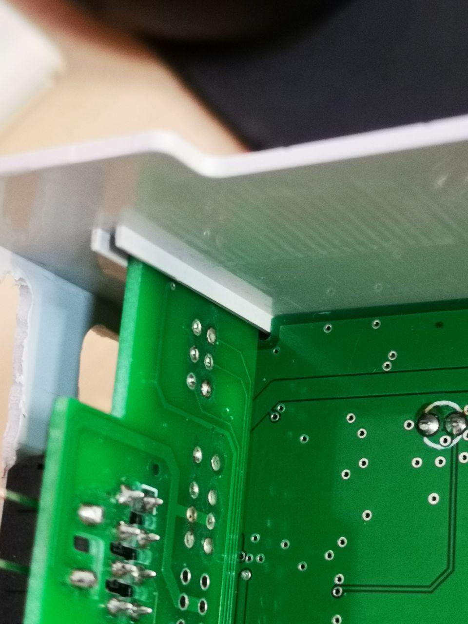
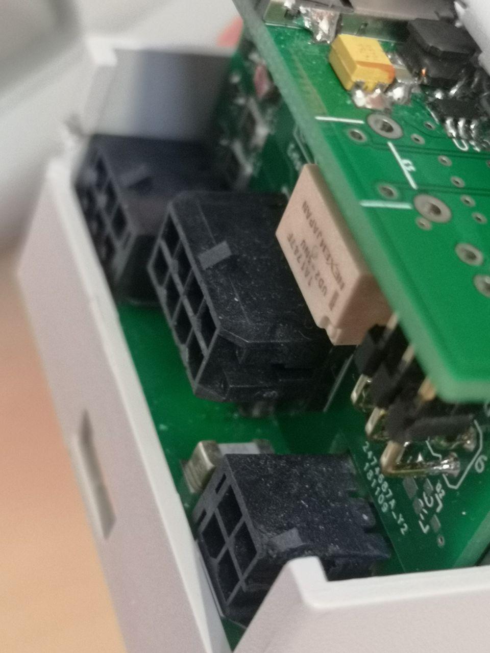
Oddly enough, the distance between this vertical board and the plastic shell perfectly fits a vertically mounted Molex connector like the ones I'm using on the bottom board, and everything lines up nicely:
![]() This vertical board also hosts the relays to drive the contactor and optocouplers to detect the high voltage on the contactors output. It's connected to the top and bottom boards with standard 90° 2.54mm pin strips, but due to size constraints I couldn't use matching female connectors so I had to solder them to the boards.
This vertical board also hosts the relays to drive the contactor and optocouplers to detect the high voltage on the contactors output. It's connected to the top and bottom boards with standard 90° 2.54mm pin strips, but due to size constraints I couldn't use matching female connectors so I had to solder them to the boards.On the other side I didn't have much space to fit vertical connectors, so I opted for the cute tiny SAMTEC CLP-106-02-F-D-P:
![]()
![]()
![]()
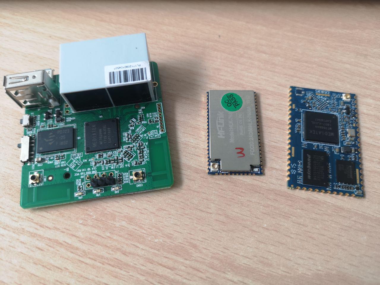
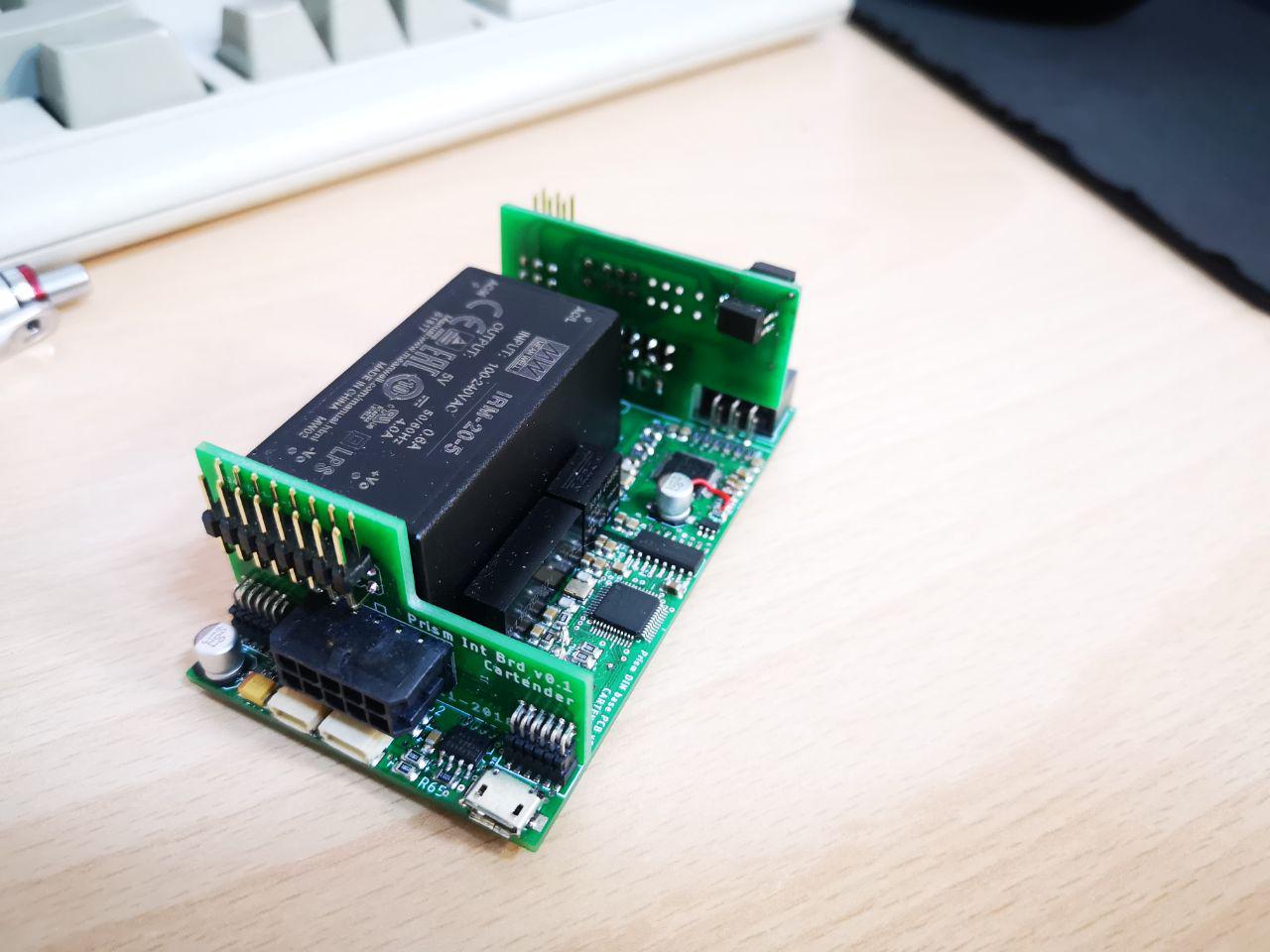
Everything fits nicely, and the only thing left to add is the Linux board. This design gives me a lot of flexibility, as I can easily replace the Linux module without having to mess around with other components. And owners can easily customize only this board, adding features like radio modules or other peripherals (i'm thinking about smartcards or TPMs for added security in critical applications). I started testing the concept with a GL-MT300N-V2 router, that is already marketed for makers - the product page proudly states "4 GPIOs for more DIY funs" as a selling point. The standard pin strips made it very easy to work with the board, and at that point I played around with the idea of using that router itself in the final product, so that everything's already working and certified:
![]() This would have been a bit expensive, also because I'd have to open up all the routers and mod them to add the serial port connection. So I decided to test some modules, and designed the first prototype to fit the SkyLabs SKW29, with a Mediatek MT7688AN chipset:
This would have been a bit expensive, also because I'd have to open up all the routers and mod them to add the serial port connection. So I decided to test some modules, and designed the first prototype to fit the SkyLabs SKW29, with a Mediatek MT7688AN chipset:![]()
![]() I'm pretty proud to say that almost everything worked on the first prototype! Thoroughly testing every part of the circuit in advance paid off, and I had to fix only three bodge wires for a missing power connection and two inverted pins on the Pilot circuit. The boards did fit well inside the DIN box, that I completely cut away to better see the internal spaces.
I'm pretty proud to say that almost everything worked on the first prototype! Thoroughly testing every part of the circuit in advance paid off, and I had to fix only three bodge wires for a missing power connection and two inverted pins on the Pilot circuit. The boards did fit well inside the DIN box, that I completely cut away to better see the internal spaces.![]()
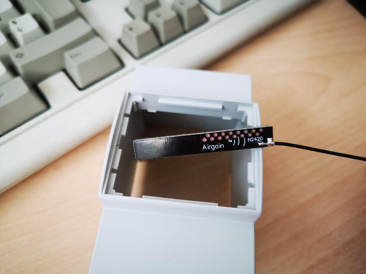
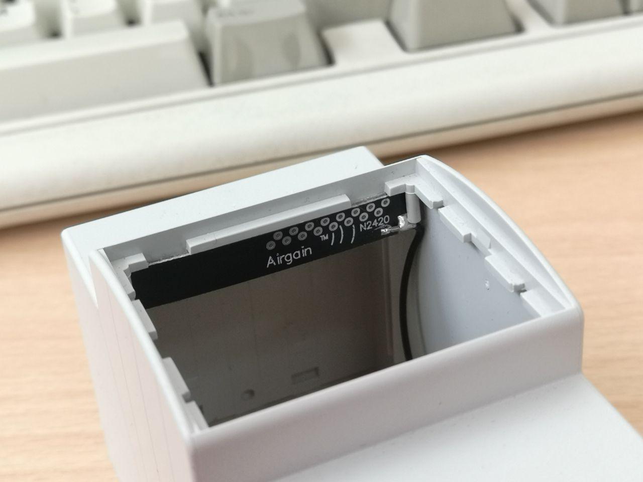
On a side note, the antenna I choose for the router module fits perfectly on the plastic slots inside the box:
![]()
![]()
While this prototype works great, there was still a lot of room for improvement, especially on the connectors selection. Molex MicroFit connectors are pretty expensive, and I'm using four of them; Samtec 90° fine pitched connectors are quite exotic and expensive too; the expansion connectors I used are too fine pitched and hard to manually crimp, and that would be ok for a commercial product but not for a DIY-oriented one (I made the same mistake on the 3310 WiFi project, but I didn't have other choices there due to space constraints).
The first improvement was to replace all the signal connectors with standard JST PHs, easy to crimp and widely available even with 2mm pin spacing. I kept the Molex MicroFits for the high voltage stuff, improving isolation on the PCB side with cutouts and protection resin, and decided to use only standard pin strips to connect the PCBs.
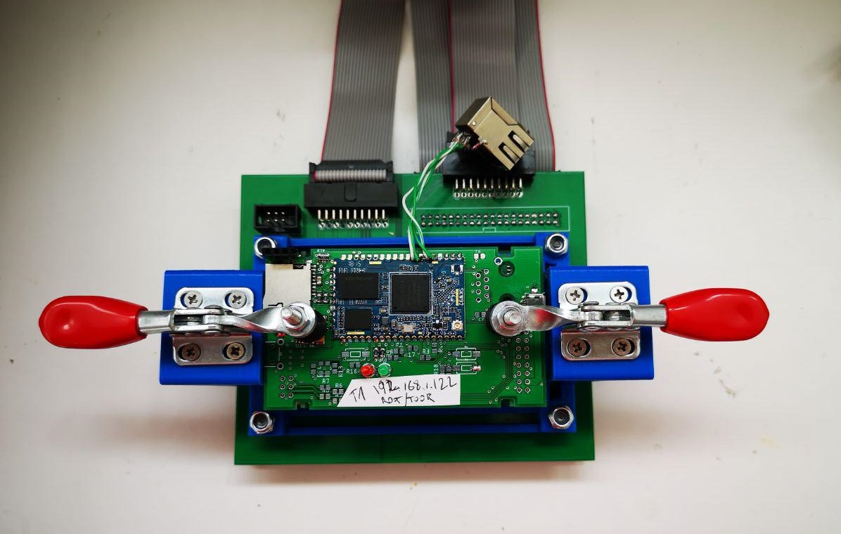
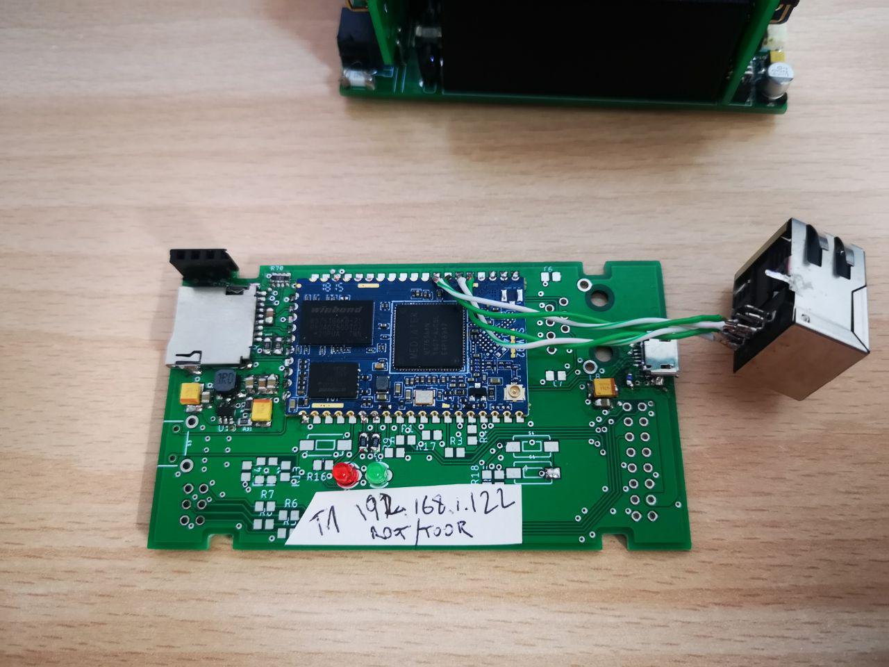
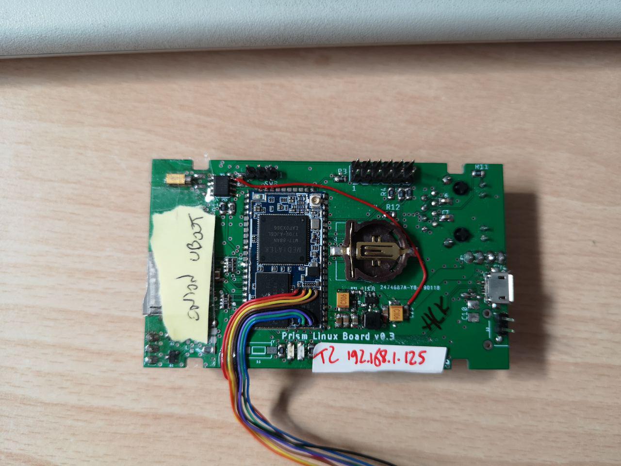
Since the HV and control electronics were pretty ironed out at this point, I started working on improvements for the Linux board. I moved from a SkyLabs SKW92 to a HiLink HLK-7688A module that is smaller, shielded and, it seemed, better supported. I also added a DS1307 RTC with its battery. Here it is:
![]()
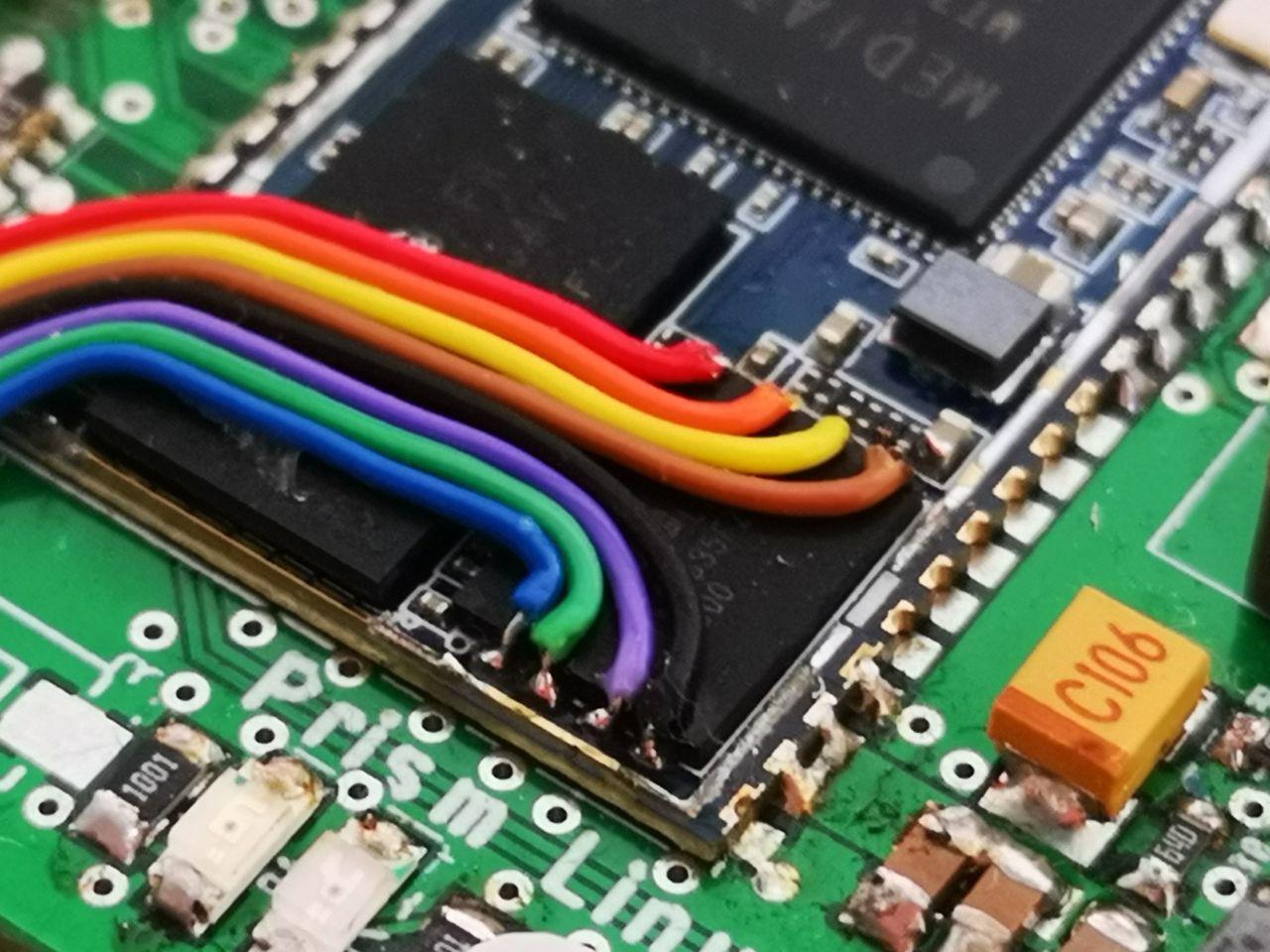
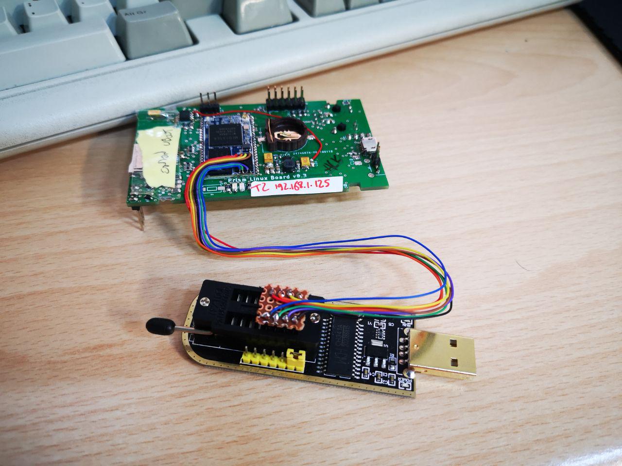
In that picture I removed the module shield because I was experimenting with UBOOT and of course I bricked the module many times in the process, so I had to solder wires to the flash to use an external programmer to restore the backups:
![]()
![]() On that picture you can also see the red wire I used to fix the power problem I had with the RTC, supplying 5V instead of 3.3V.
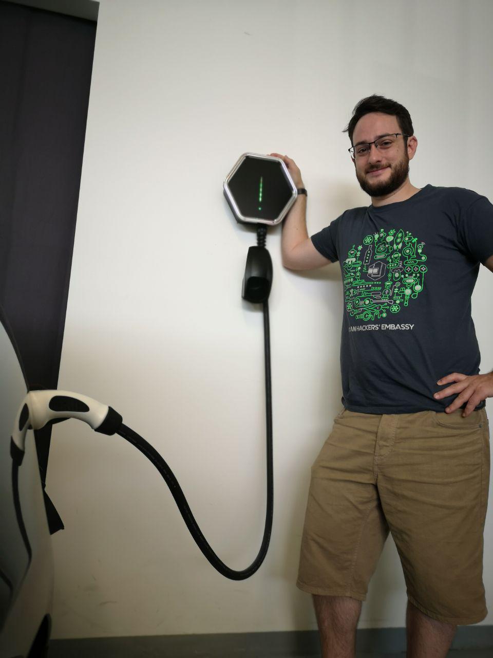
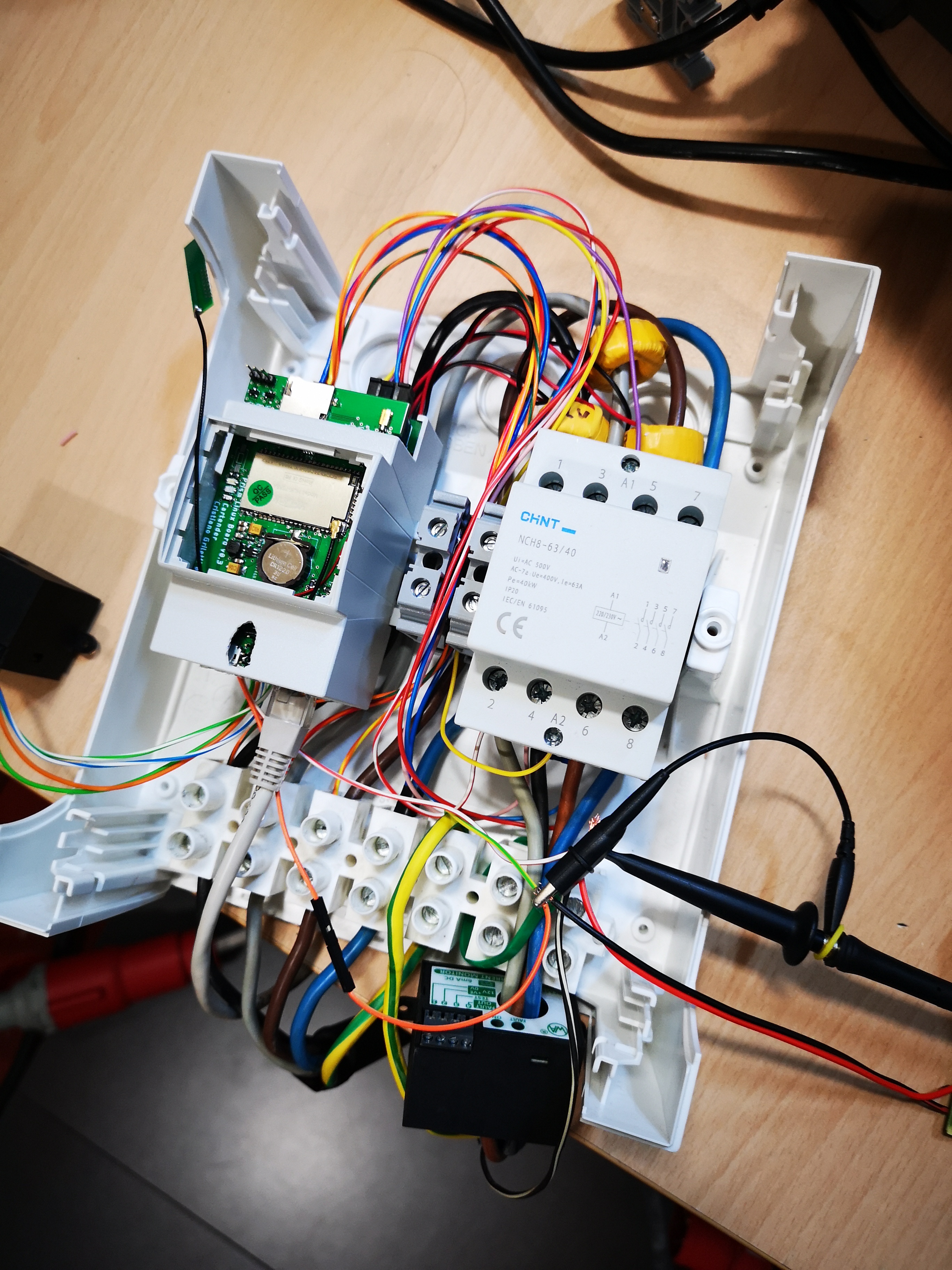
And here it is, happily charging a car! :)
On that picture you can also see the red wire I used to fix the power problem I had with the RTC, supplying 5V instead of 3.3V.
And here it is, happily charging a car! :)![]() I'm almost done designing the new revision of this part, but in the meanwhile you can find all the design files, the board templates for the enclosure and the cables diagrams on my github repo. The firmware for the base STM32 handling the charge process is here.
I'm almost done designing the new revision of this part, but in the meanwhile you can find all the design files, the board templates for the enclosure and the cables diagrams on my github repo. The firmware for the base STM32 handling the charge process is here. -
My 2 cents for Linux
09/24/2019 at 11:28 • 2 comments![Image result for tux chip linux]()
While I am definitely a hardware guy, I also really like to write software, either as the firmware for the devices I build or as quick hacks to improve my daily routines. I've always been a Windows guy because all electronics development software was only available for that platform until recently, and I have a love/hate relationship with Linux: I tried many times to use it as my main OS, but I always had to revert to windows for one reason or another (but mostly laziness, I must admit).
---------- more ----------I had the chance to "contribute" to the linux kernel development two times. The first time, about 6 years ago, I couldn't set a custom baudrate on a PL2303 USB-serial adapter. I found the problem in the devices kernel driver: they were basically comparing the requested baudrate with a fixed list of baudrates, and setting it to the closest if it's not among the predefined values. Then they proceed calculating and setting the clock divisors with a generic formula that should work with "any rate between 75 bps to 12M bps". That is pretty stupid, as it doesn't solve anything; if a users selects a wrong baudrate by mistake, they wouldn't be able to communicate either if we calculate the divisors with the formula or if we force some other baudrate on them. So why bother with a table, at least try to calculate the values and see what happens! That seemed pretty straightforward to me, so I naively tried to politely explain the problem to the driver maintainer. In the followup discussion the stubborn maintainer repeatedly refused to consider the proposal saying that the driver worked that way for the past 10 years; he probably didn't even look too much into the issue in the first place, or he would have noticed the problem. At that point I was very frustrated and gave up to go back to windows, but luckily Reinhard Max picked up my fight and finally convinced the maintainer that that was the way to go, resulting in this patch! The mailing list discussion is quite interesting, and I learnt a lot about the correct methods to report issues:
- clearly describe the problem and the software versions you're running
- compile and test any proposed patch (big problem if you're a novice and have to learn how to compile the kernel from scratch)
- have A LOT of patience to deal with maintainers, that to be fair are probably overwhelmed by requests
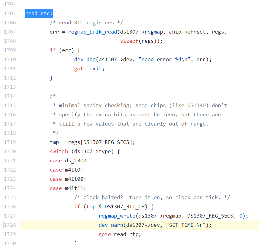
That helped me when I found an issue in the DS1307 RTC driver while developing Prism. In the first version of my linux board with that IC, I mistakenly connected the RTC supply to 3.3V instead of 5V. After enabling the RTC in the device tree and recompiling the image, I got an infinite loop at boot that completely locked me out of the system, being it a single-core CPU. The driver kept on printing "SET TIME!" on the serial port, so I looked for that string on all the files in my build folder. And there it was, at line 1728 of rtc-ds1307.c! With a nice "goto" on the next line, pointing at a label 23 lines above, generating an infinite loop if a bit is set.
![]()
This time I tried my best to make a good contribution, explaining the problem, making a patch and testing it (I learnt how to compile kernels in the meantime, also thanks to OpenWRTs great image builder). I basically checked the value of the problematic register, compared it to the 0xFF I was getting (impossible by the datasheet, and plausible in case of IC failure) and exited the loop gracefully.
And the maintainer basically put the blame on me because I should have used other unspecified methods to read time (I used the default stuff from OpenWrt) that wouldn't cause a boot lock despite infinite loops.
I politely replied again trying to explain the problem, and that a driver shouldn't cause an infinite loop anyway, and he actually listened to me, admitting that he was too quick to dismiss the issue! That made me super proud, but he didn't actually accept my patch and wrote a way better solution to fix the problem.
What's the lesson here? I was pretty disappointed by finding these kinds of bugs in Linux, I always imagined it to be better than that. It's running on trillions of computers, isn't it? But it's made by humans that most of the times don't get paid for the work they do, and depending on their expertise their code varies in quality, right? Well, I was reporting these bugs that I found during my "job", and the solutions I offered focused on solving my specific problem as efficiently as possible and weren't designed to fit the big picture: instead of spending days refactoring the code to fix the "goto" bad practice altogether (while possibly introducing more bugs), I just added a check for a specific type of failure and called it a day.
So I guess it's quite the opposite, a lot of the problems in Linux are due to (mostly paid) people pushing stuff to fix shit quickly and cheaply, and the good code is written by passionate persons taking the time to understand how every piece fits together... And anything in between. I'll do better next time, I promise!
I still have a lot to learn about Linux, but I was very lucky to meet a lot of great friends at hacker camps that can help me fill the gaps; among them one of the best developer I know, so good and expert in privacy that doesn't even want to be named (LOL), that is helping me with the development of Prism. Now I can sleep better knowing that the Linux part will be handled by a real Pro :)
-
RCM direct current sensing - how it's done
09/16/2019 at 18:24 • 0 comments![]()
This post is written by my friend (and now colleague/intern :) ) Michele.
Our target users for Prism are mostly hackers and passionate people playing around with EV technology; for this reason we strive to make Prism as safe as possible even for the most edge cases.
---------- more ----------An essential part of the safety system is the RCM, acronym for Residual Current Monitor. As the name suggests, this component has one simple job: measuring current leaks. And I'm sure everybody here already knows how an AC RCD/GFCI works, or you can find plenty of great articles to learn from. To sum it up, the RCM measures the current passing through the neutral and live wires inside it. In normal conditions, all the current passing through the live wire should return back via the neutral wire, "cancelling" each other. In case of irregular operation - like someone touching an exposed wire - we have some current flowing to earth and not returning through the neutral. In this case the RCD detects this difference and signal fault on its output, triggering a circuit breaker to stop this current path.
And this is pretty easy if you're just measuring AC currents - a simple current transformer can do the trick. But our electric cars also contain high voltage batteries, that can leak dangerous DC currents! This risk is considered by standards organizations, and IEC released the IEC 62752 and IEC 62955 standards to describe the requirements for "In-cable control and protection device for mode 2 charging of electric road vehicles" and "Residual direct current detecting device (RDC-DD) to be used for mode 3 charging of electric vehicles". A DC RCM is not required for domestic installations, but since our customers will probably charge DIY EV conversions with increased risks of DC leakage we decided to include this protection by default.
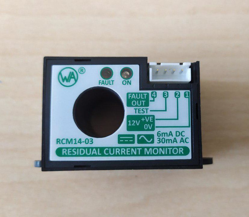
To comply with the standard we selected the RCM14 from Western Automation, a really nice and compact RCM that trips at 30mA AC or 6mA DC.
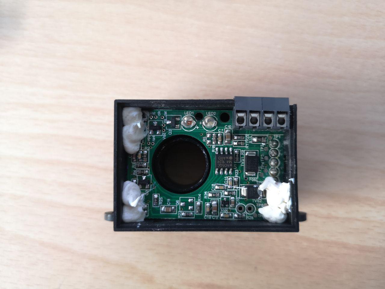
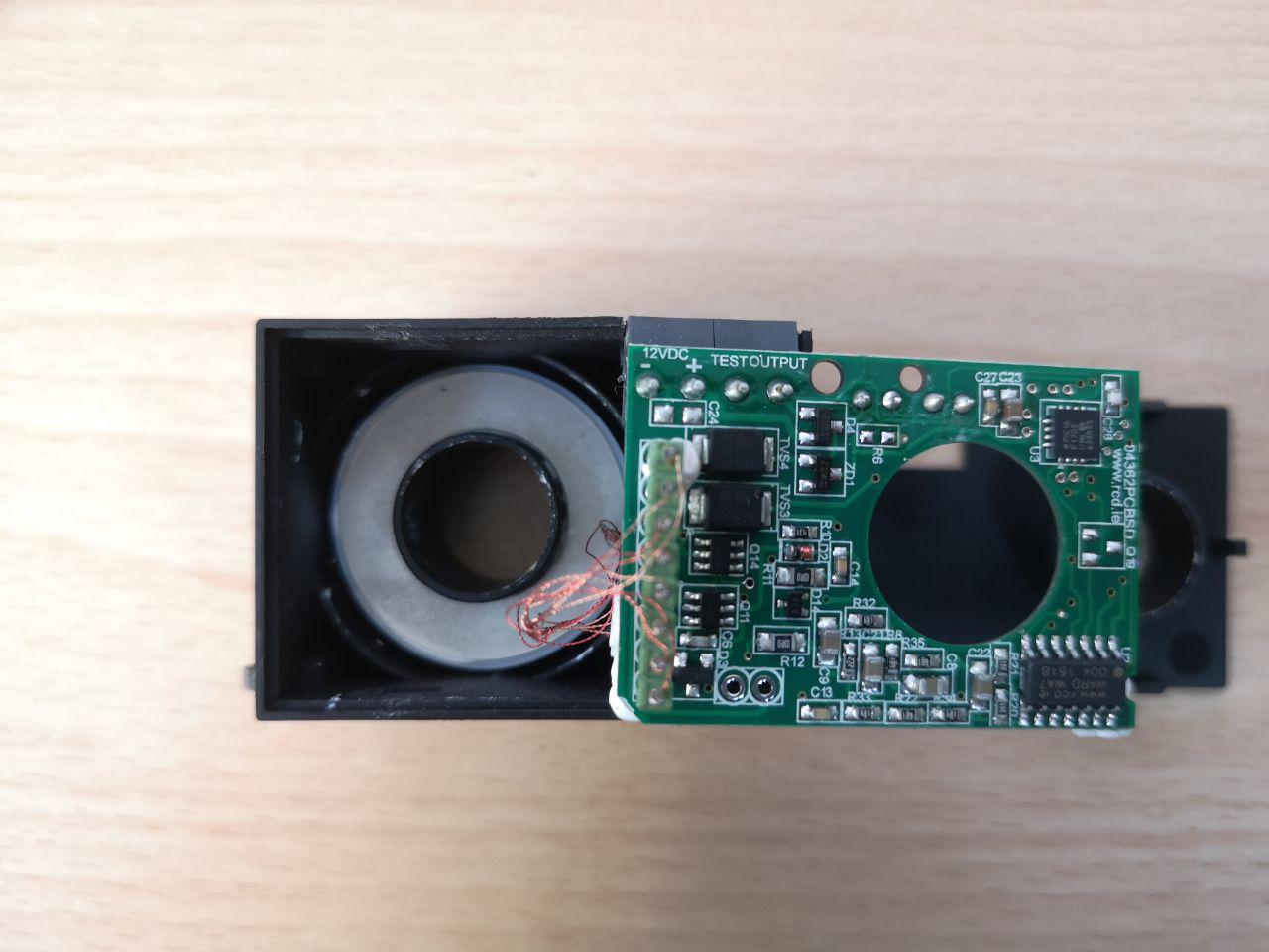
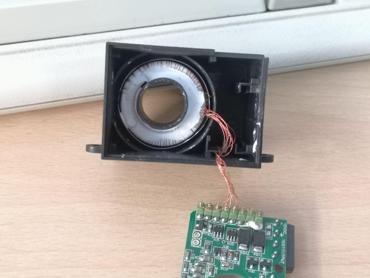
But how is it capable of detecting a direct current if it looks like a normal current transformer? Our guess was that they're using a hall sensor to measure that, but there's no trace of it inside:
![]()
![]()
![]()
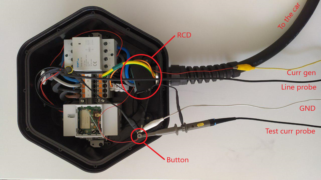
At that time Mastro Gippo was doing some performance testing on the RCM and the contactors. In his setup he ran a wire through the RCM, shorting a constant current generator through a switch. To measure intervention time, he connected one probe of the scope across the wire and the other probe to the contactor output.
![]() This test showed interesting results: the current through the wire (in blue) was not constant, it had a square wave component!
This test showed interesting results: the current through the wire (in blue) was not constant, it had a square wave component!![]()
This gave us a precious hint to understand how this works.
The Fluxgate technology
The principle behind this application is the fluxgate magnetometer, a device invented in the 1936 and used during WWII to detect submarines.
Here is a simple explanation on how it works:
Fancy, isn't it? But I want to know more about how this device works, so let's dig deeper.
This type of magnetometer takes advantage of a property called magnetic hysteresis. If we apply an alternating magnetic field to a ferromagnet and plot the resulting magnetic field and the magnetic flux on a graph, we get something like this:
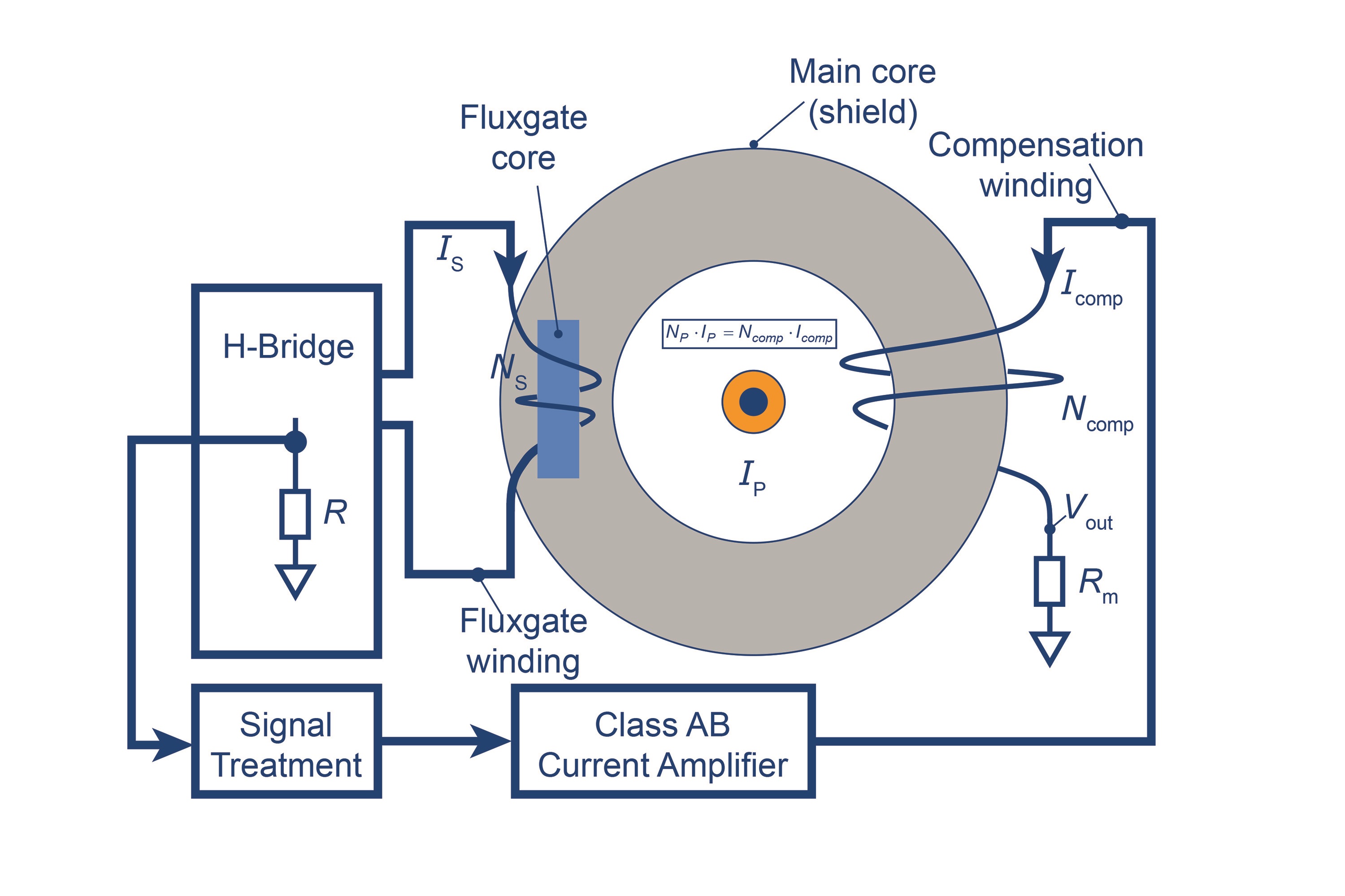
To measure this property we can take a ferromagnet, wrap two coils of conductive wire on it and apply a square wave to the primary coil (fluxgate winding in the picture below). The result is an alternating magnetic field or, from the secondary coil perspective (compensation winding in the picture), a square wave current. The hysteresis cycle is perfectly symmetric, so the resulting voltage is symmetric too.
![]()
This changes if there is a constant magnetic field B0 close to our setup. The cycle is the same, but instead of starting from the middle of the graph (B = 0) we start from B = B0. It's like having the same graph translated down by B0.
![]()
The cycle and therefore the voltage at the secondary is not symmetric anymore. We can measure this asymmetry and apply some math to get the value of the external magnetic field B0. This process is not simple, but you can learn some more details from this article. It involves harmonics and Fourier Series expansion!
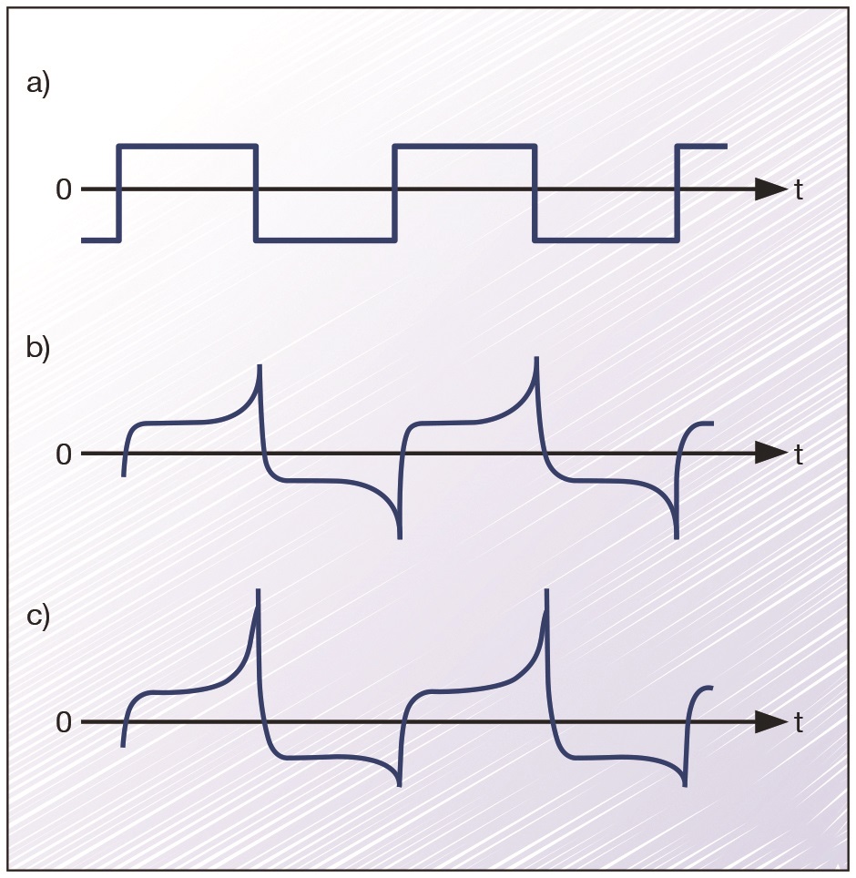
![]() Fluxgate drive waveform (a), and Fluxgate current in the absence (b) and presence (c) of an external magnetic field
Fluxgate drive waveform (a), and Fluxgate current in the absence (b) and presence (c) of an external magnetic fieldThat's it: a DC current across the wire through the RCM will distort the symmetry of the fluxgate circuit which will fire the RCM output if this current is high enough.
So why was the current measured by Mastro Gippo a square wave instead of constant? The overlapping wave is caused by the magnetic field induced in the magnetic core by the fluxgate primary coil. The alternating magnetic field causes an EMF - and thus a current - across our test wire.
Mystery solved!
But what about the tests? Well, the standards define precise intervention time requirements:
![]()
First we measure the net intervention time of the base circuit, from the moment the RCM signals a fault to the moment the contacts disconnect. All tests are performed in normal usage conditions, while charging a car; that's why the output voltage doesn't settle immediately (there are standards specifying exactly how quickly the voltage has to settle below a safe voltage, but that's the cars responsibility).
Worst case measured: 15,2ms.![]()
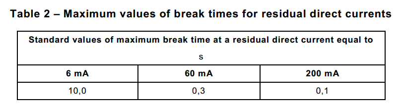
Now we can add the RCM to the equation and measure intervention times according to the table (notice how the square wave becomes less influential as the current directly applied to the wire increases):
Test1 – 6mA DC
Required intervention time: 10s
Worst case measured: 249ms![]()
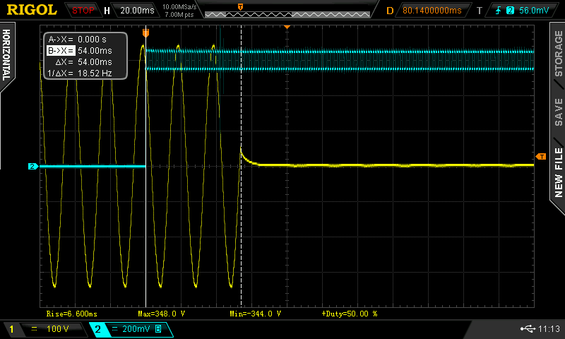
Test2 – 60mA DC
Required intervention time: 300ms
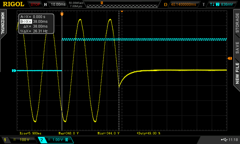
Worst case measured: 54ms![]() Test3 – 200mA DC
Test3 – 200mA DC
Required intervention time: 100ms
Worst case measured: 38ms![]()
All tests passed with flying colors! Stay safe :)