-
What's implemented
08/20/2014 at 11:40 • 0 commentsYou can see the progress in the quarterfinal video:
Works:
- 1st button - backlight control
- 2nd button - 16 modes of spectrum and VU meter: https://cdn.hackaday.io/images/8052571408534158067.png
- 3rd button - 8 different symbols to draw spectrum bars
- 4th button - 3 different algorithms to draw spectrum: linear, linear with small values boosted, non-linear
- option jumper - vertical VU mode:
Missing:
- serial interface
- vertical VU not finished
-
The stress of quarterfinals
08/20/2014 at 11:25 • 0 commentsA check-list of quarterfinal:
- The video (and a link to the video) no more than 2 minutes long on YouTube -
- 5 Project Logs
- The system design documents: schematic - https://github.com/CrazyChip/spectrum/blob/master/schematic/sa.pdf and the block diagram of the system - https://cdn.hackaday.io/images/3729271408312529258.png
- Licenses - everything under GPLv3
-
The hardware on my table
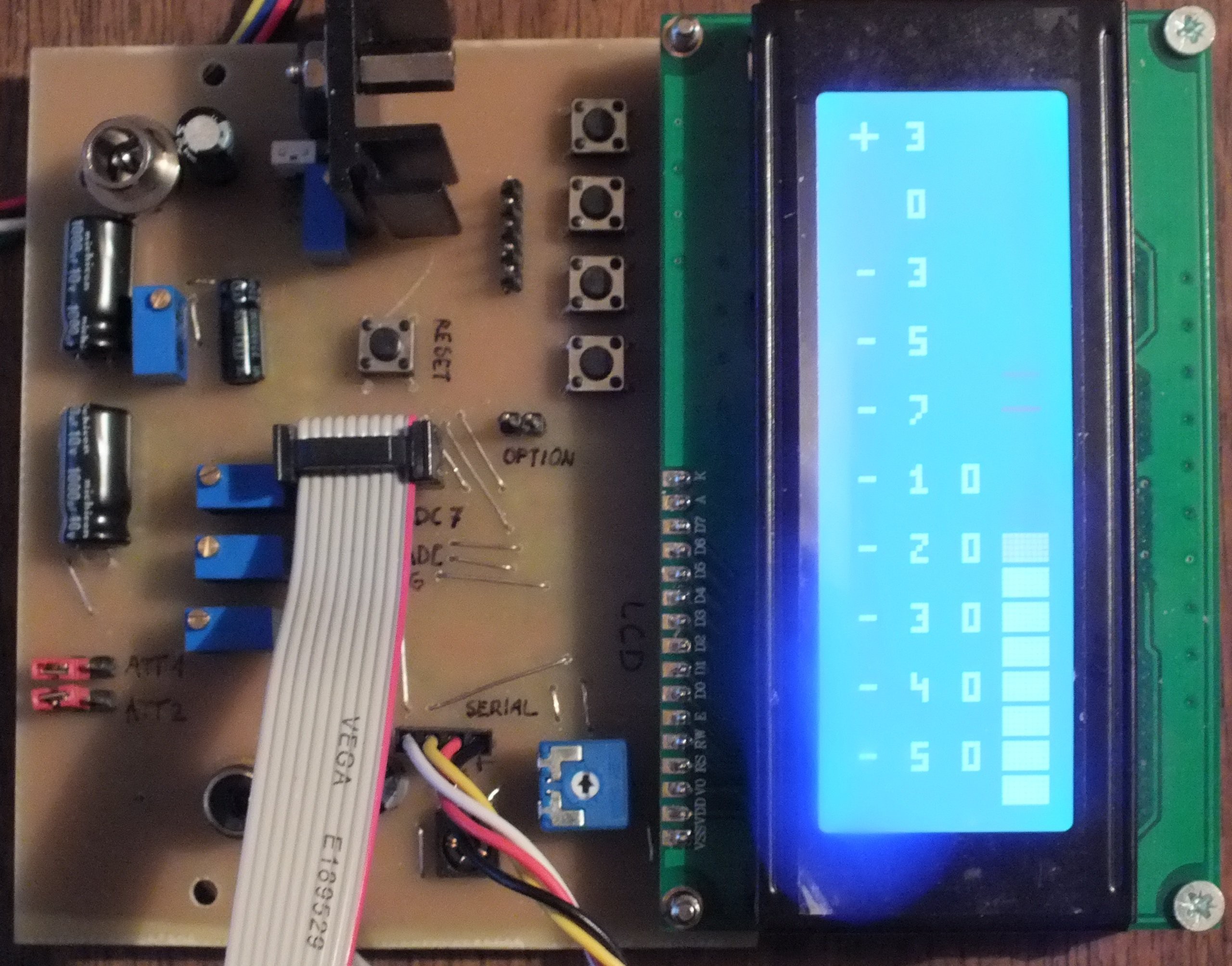
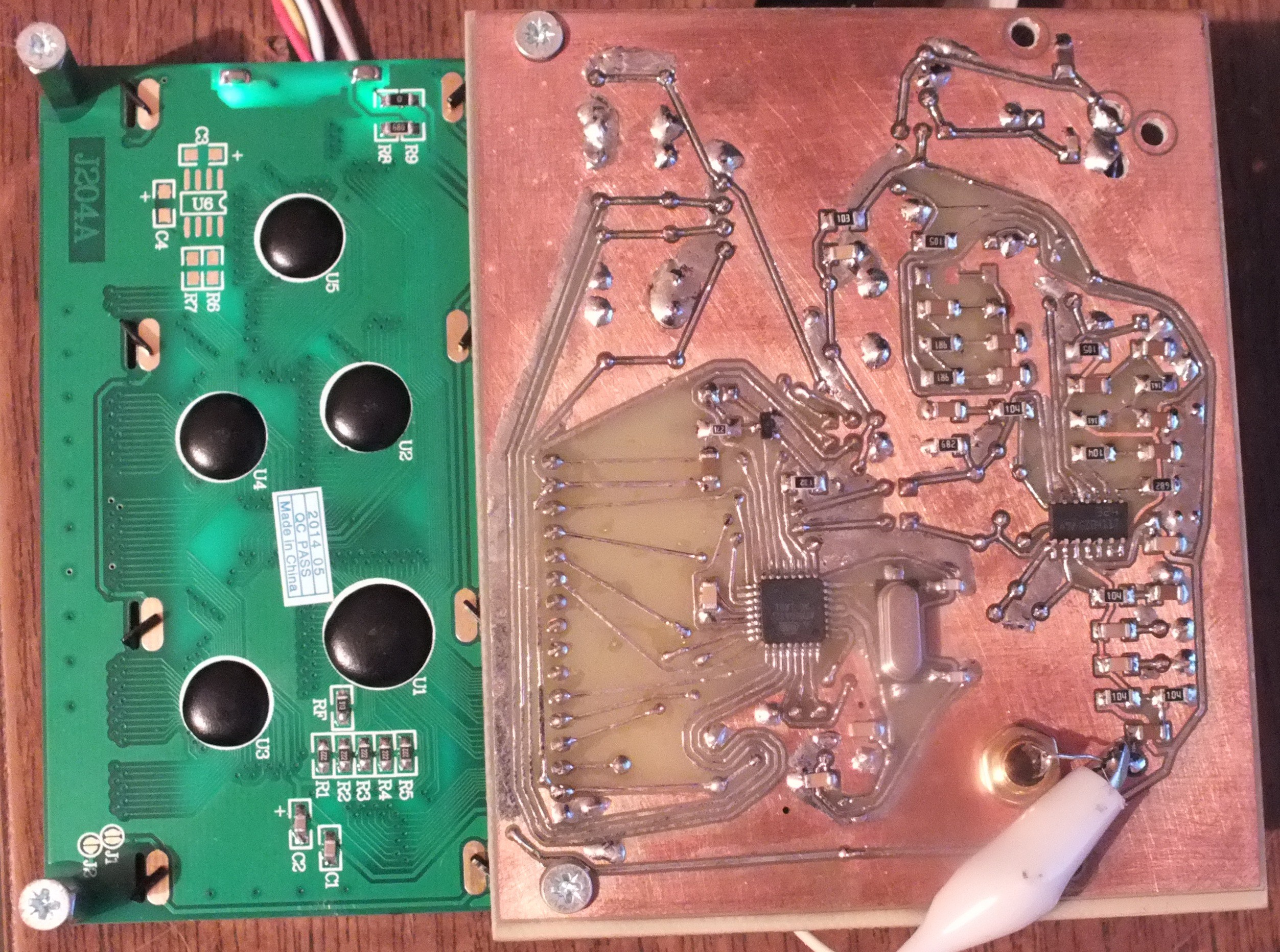
08/10/2014 at 13:27 • 0 commentsI soldered all the parts. The layout of the board is terrible but it works.
Some notes:
- LCD connector is soldered upside down due one-sided PCB. The final version will be soldered on another side of the PCB.
- Trimmers are placed randomly. Not easy to find which does what. Too many trimmers and jumpers. I plan to simplify the input filters and reduce the number of these jump&trim.
- Optional (and different) connectors for audio input (e.g. 3.5mm socket) and power (e.g. small screw terminal block) would be convenient.
- Bad footprint of power connector.
- USB->serial chip on board (e.g. PL2303) would help with the external connection
So, looks like a list of several small improvements for the next version of the PCB :)
-
Block diagram
07/29/2014 at 09:16 • 0 commentsBlock diagram added to show possible connections of the external devices
![]()
-
Kicad project
07/22/2014 at 20:05 • 0 commentsKicad files committed to GitHub
https://github.com/CrazyChip/spectrum
Schematic in PDF also included:
https://github.com/CrazyChip/spectrum/blob/master/schematic/sa.pdf
One-sided PCB is traced with Toporouter for prototype only.
A smaller two-sided PCB is planned after testing the prototype.
Youtube video shows a very early prototype implemented on Arduino using 20x4 character LCD.
Test signal is generated with Matlab (background music is not used as a signal).
-
Input filters
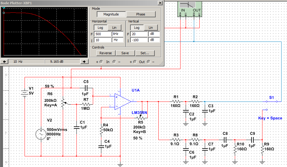
07/22/2014 at 13:54 • 0 commentsDesign stage: two low-pass filters - 1kHz and 16kHz - simulated on Multisim.
![]()
 CrazyChip


