 Eric Hertz
Have an interesting toggle-switch... pretty high quality, made in the USA, wound-up in my collection probably more than 20 years ago [I'm pretty sure I remember the day/person], and... it's still available new at regular suppliers. [This is the kinda quality design we're talking about].
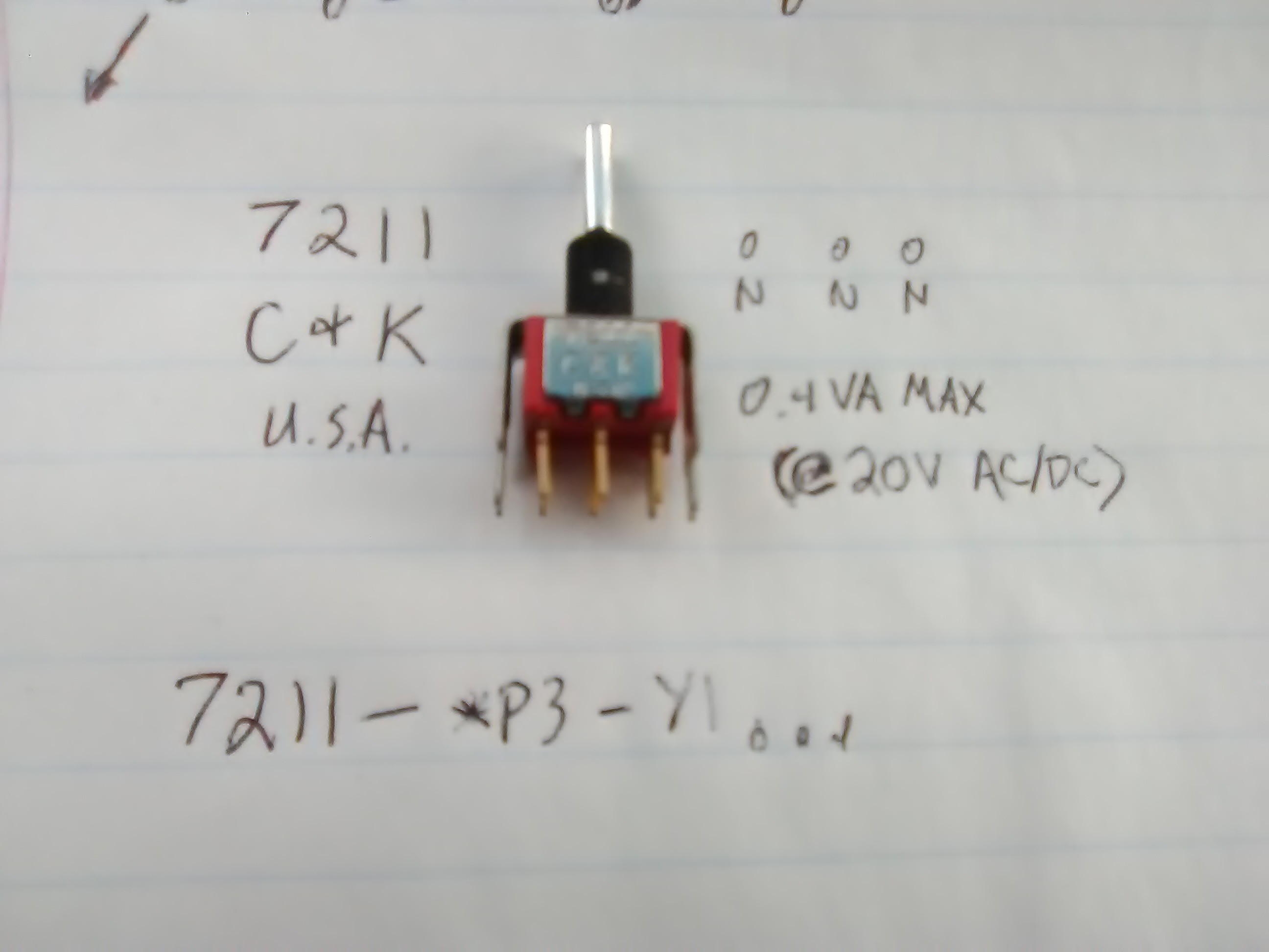
C & K 7211.
Two odd things I never noticed about it in my previous uses, guess it didn't matter there:
A) On-On-On (DPDT, three positions, so what's with three Ons?!)
B) [Relevant to current project] "0.4VA MAX"
First-off, if VA means what I think it means, then this switch is no-go for my project. [And sure-enough, it would seem that way].
I had a bit of difficulty finding a decent explanation of this rating, so here's the best reference I found:
http://www.aeroelectric.com/articles/Switch_Ratings.pdf
Briefly: there are two common contact platings, gold and silver. Gold's used for low-power [logic], silver for high-power.
Silver oxidizes, so arcs caused by high-power switching burns off that oxidation. It's by-design! So silver-contacts aren't so great for low-power/non-arcing switching.
Meanwhile, such arcing would burn off the gold-plating on low-power contacts, and you'd be left with tin or copper [or something] contacts which make poorer contact than silver, and also oxidize and such.
So there you have it.
And, from the sounds of things, 0.4 VA MAX at <28V [20V AC or DC, per my datasheet] is pretty much standard for gold contacts...
And, yes, that does seem to be a measly 20mA at 20V = 0.4V*A = 0.4W. But it's a little more complicated than Watts, what with AC, RMS, peaks, etc. Or with DC and inductive loads [motors, or even long wires] and Capacitive loads [with large inrush currents, *during* switch-bounce!].
So, I guess the answer for my project is that, sure, this switch, if it had silver contacts, would handle 5A @250V [AC]... I thought it seemed pretty heavy-duty... And it'd probably do the job of switching 40VDC unlikely-max 3A [most-often a fraction] for a while even with bare copper or tin.. but probably not an ideal solution.
BTW look into that document, also, for info on derating for DC circuits [no zero-crossing = longer arcs] it's something like x Amps @ 120VAC -> x Amps @ 14VDC!
----
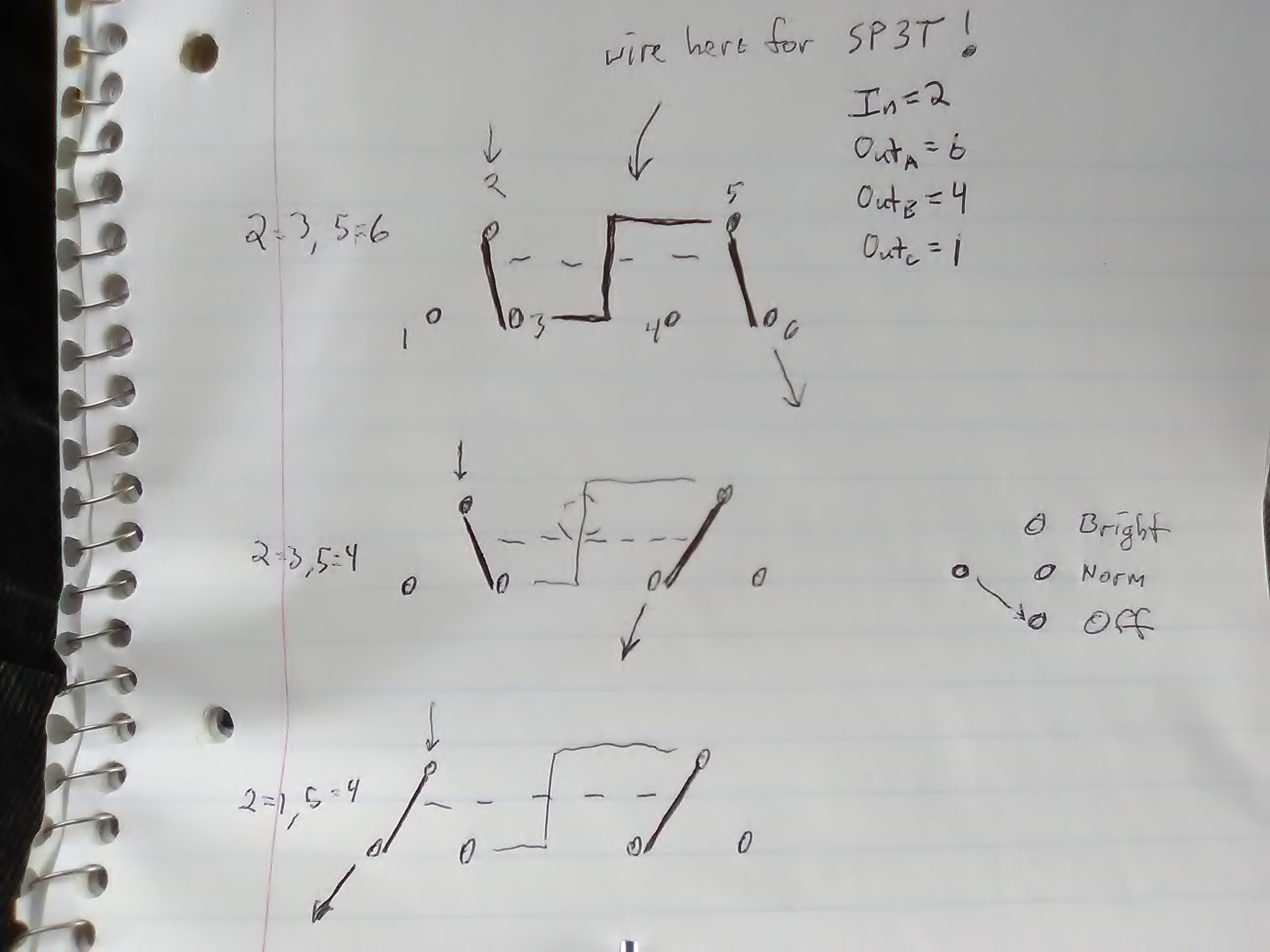
Oh, and finally, On-On-On, that's also nicely-covered in there. Basically it's like a typical three-position DPDT switch, but the middle position puts it in a weird-to-me state where the two poles are in opposite positions [What?!].
I once used these guys to drive/reverse the motors in a wired toy-car [hahaha 0.4VA my a**]. It worked... but now I see the middle-on was actually *braking* the motor [shorting its winding via one of the power rails]. Hadn't noticed. But, could be handy.
And, finally, they can be wired as a SP3T switch... cool!
which, also, makes for Off-On-On as a possibility [e.g. Off, Slow, Fast, or Off, Dim, Bright]
Whoda-thunk? Certainly wouldn'ta thought to look for such a switch, expecting it to be somewhat common!
Discussions
Become a Hackaday.io Member
Create an account to leave a comment. Already have an account? Log In.
Mouser has the datasheet which has an explanation of the on on on showing which terminals are connected in each position: https://mouser.com/datasheet/2/60/7000toggle-1315363.pdf
Are you sure? yes | no
indeed! Thanks for looking that up.
Imagine an electronic component still manufactured 20+ years!
Are you sure? yes | no
First page of search results. No suprise some components are in production for a long time. If there's a market for it and it addresses the requirements, why not?
Are you sure? yes | no