Eric Hertz
-
Your goop ruined my vias!
05/21/2020 at 08:00 • 3 commentsThis was sitting as a draft, a bit outdated; the printer now works [except for a few dead nozzles], but I'll write about that adventure later....
----
been trying to get an old printer running... it's a portable doodad which probably cost some executive a small fortune back in '91. But it's got a sticker on it for $3.50, I'm guessing an old buddy grabbed it from a thriftstore back before he decided guitars were better at picking up chicks than robots, and gave everything to me... I held onto the things that could plausibly one day be useful to <i>someone</i>.
This printer I never planned to find a use for, and actually put almost immediately in a box marked "To Donate" [to a thriftstore]. I'd done quite a bit of research buying my desktop photo-quality printer, I'd planned to hold onto for decadeS, and invested nearly $300 to do-so. I didn't even have a drivers' license for another fifteen years after, so I really saw no need for a portable inkjet... Sufficed to say, this printer's been in *my* storage for nearing 20 years... but these days I actually have a use [if not a need] for a *portable* printer...
so, cool-beans!
This thing's actually EXTREMELY well-documented... right down to schematics *and* functional descriptions of the subcircuits. And the service manual's even kinda funny in some places. Its ink cartridges are well-documented, and even still available nearly 30 years later; which actually isn't a huge surprise, because at one time they actually made multiple printers, over several years, even from different brands, which used the same cartridges.
[This thing shoots out droplets at <b>12 Meters Per Second!!!</b> I wonder how/if that could be used?]
So... this thing might be a useful tool for some time, if not, frankly, a piece of test equipment which again might be useful for quite some time.
Here're some thoughts, in the "hacker" realm... old printers like these were *designed* to be compatible with even older printers... plausibly all the way back to the days when one might literally log on to a system with only a keyboard and [dot-matrix? Teletype?] printer... no monitor!
Simple commands can be used to print one line [maybe even one character?] at a time. E.G. in linux: 'echo "hello" > /dev/lp0' And maybe even one /character/ at a time E.G.2 'echo -n "a" >/dev/lp0'. Nevermind the fact they'll work with *countless* machines of the era, without special drivers!
Now... imagine how friggin' useful such a thing could be in *this* era... e.g. attached to an arduino... true, it's a little more difficult than using printf [or cout?] statements, because it has a parallel, rather'n serial, interface. But only slightly. in fact, serial to parallel adapters existed for exactly that purpose, and even modifying printf to output parallel isn't particularly difficult. Oh, sure... debug-info may be best-suited to a console/terminal window, but having a physical printout of whatever you want at your fingertips?! How is it this ain't "a thing"?!
I dunno what newer printers do, but older ones like this were actually capable of *both* "text-only" <i>and</i> graphics... and that was no small feat on their part. In fact, it was so difficult, printers of the time had processors *on par* with the computers' CPUs of the time, just to handle e.g. rendering inbuilt fonts... Similarly; modems, and even some [e.g. Commodore] floppy drives were full-on computers in themselves, again, on-par with the systems that used them... because those seemingly-simple tasks--many of which we've exiled to "obsolete," such as converting a single byte of ASCII input into Hundreds of pixels on a piece of paper--were once handled by the devices themselves, rather than by the computer. In a way, many older peripherals are *way* smarter than the newer, seemingly more sophisticated ones, which require the *computer* and drivers to do all the work. [See also "winmodems," wavetable MIDI, and "framebuffer console"]...
So, yahknow... as a 1337 Haxor, I kinda like making use of such things' abilities [hey, there's a "Print Screen" button on most keyboards that did/does!]
...
Anyways...
This printer is non-functional, presently... Its dysfunction looks to be mostly power-related. It takes a 6V-9.5V input and breaks that out to a 5V output, a *switched* 5V, 14.4V, and ~20-22.5V. Yeah, two boost converters from the era when switching supplies used BJT rather'n MOSFETs. Apparently this means using BJTs which were *barely* realized, *just* before MOSFETs took over. The 22.5V boost converter's BJT has a saturation-voltage [VCE-sat] less than half a volt [was it 0.03V?] at several amps... and... well... apparently that's uncommon... to even be specified in datasheets! [I later found one locally that claimed "low saturation voltage" of 1.2V! At fewer amps!]
Anyhow, that *uncommon* BJT let out smoke... and somehow I mistook it for another on the board, which happens to be far more common and a *mostly-compatible* cross-reference replacement available at my nearby store... but. $7.50?! I wouldn't feel right--rather, I'd never live it down--spending that on a lowly transistor, unless it was *exactly* what I needed, especially in an era when the stock is probably as old as the store and still sitting there [read: decent supply, no demand... sad, really... but not at all surprised, what with so many past-buddies switching from electronics to guitars, or XBoxes]. So I checked the relevant specs and found a suitable replacement equally as old for ~$3, which is admittedly still a lot for *one* BJT, *BUT* *BUT* available immediately, and *NUMEROUS* other justifications. [Thank you, Fry's... PLEASE stick around!].
But, it turned out the one I thought blew smoke was *not* the one that did.., and the one that did... well, frankly, is darn-near a freak of nature... so at 5 minutes to closing time I ran in and grabbed darn near every seemingly-plausibly suitable replacement under $3bux [I'da spent $7.50 for a direct replacement, at this point, but this was rare; VCE-SAT=0.03V@4A?! B J T ?!]...
So, I fought this for a while... threw in the closest-match.... again, sat-v=1.2 vs. 0.03[?] is a *huge* difference... but I figured it *might* work, since the switching supply relies on a feedback loop...
....
So, several *several* hours later...
It seems the switcher-chip is resetting due to an undervoltage/brownout/"short-circuit" condition... yet nothing, even the new transistor, seems at fault....
But get this: the feedback voltage at the switcher-chip is 0V. What?!
Even if the switcher-chip was dead, the feedback voltage should've been some fraction of the supply voltage [6-9.5V], a fraction giving ~1.2V... yet it was 0V-0.03V.
WAIT, WHAT?
So, I start probing around... and, mind-you, this is *hours* of troubleshooting later... and I discover that the feedback pin is *not* connected to the feedback voltage!
So, I probe around some more... and the feedback *voltage* is at a topside-via, and the feedback *input* [~0V] is at the bottom-side of that same via. Yet, the two are not connected!
It seems a big-ass electrolytic capacitor, which spilled its guts [and I replaced], leaked goop *through* this via, and ate up the through-hole plating!
Well, shit. I bypassed that via, and suddenly I have stable [boosted] voltages! No more "undervoltage"/"brownouts," steady boosted voltages... yet, get this... the printer is acting *exactly* the same!
So... I guess that electrolyte goop eats copper?! *Numerous* vias filled with that same black sludge...
WEE!
---
Again, days [weeks?] after writing this, the printer is running! I'll get around to that write-up later. Oh, and... yes, single-character printing is a thing! And so is reverse linefeed! I've got big plans, and a simplistic proof-of-concept that's fun to watch. More later...
-
Projects!
05/06/2020 at 19:48 • 5 commentsbeen working on my computer... for months... Long friggin' story involving trying to put it in a sturdy housing so as not to damage anything... and friggin' destroyed the mobo in the process.
Thankfully, I remembered I had a Raspberry Pi Zero I only turned on once... and, I managed to get that working. Then I powered up the display before powering up the Pi, and my stupid DC barrel plug shorted out something through the HDMI cable. No more HDMI output. But, the activity indicator on the Pi was still blinking(!). So I wired up the composite output, and finally got my old composite LCD running... and it booted!
But, barely legible.
So, long ago I found a destroyed portable DVD player... the screen looked OK and oddly the board had labelled testpoints for all the LCD signals. Eventually got it running off the Pi's "Display Parallel Interface"
Then I *finally* got to my original goal of packing it into a sturdy housing... two or three months in.
Then the original original goal of setting up a working system I can actually use for projects...
Which means backing up four previous dev-systems' drives to this one, and slowly merging everything into one directory structure... which has been a weeks-long process, as well. But, once that's done, I'll finally not have to carry around four old hard drives and try to remember which one has what I'm looking for, etc.
So, midway through the process I changed a setting so I could legibly fit two terminal windows... and X broke. Really.
Thankfully, I've been doing a lot of intermediate backups, so it only took a day to figure out which files were modified [aside from the slew of reorganizing I'd done prior], and put them back the way they were. [Note: be *very* careful using the Pi configuration buttons for "small screens" combined with the "Desktop Pager"! It seems one of them changed some settings for/to a display manager which wasn't installed?!]
Anyhow, *finally* I've got almost all my files from decades[!] of previous systems all in one location that I can finally get to my original original original plan to actually work on some projects; revisiting old ones, building on them, starting new ones with my old dev-environment/libraries/etc.
And, another original original original goal of having all my photos [and music] accessible [and sortable] from one location.
Whew! MONTHS.
-
Sad Scopey
04/24/2020 at 06:50 • 2 commentsPreface: I've done a lotta diagnoses/troubleshooting since shooting this vid. I've got some pretty solid theories and a lot of interesting and confirming observations *after* this vid was filmed...
Key factors:
I'm running it off a cheapo car inverter, which appears to output a bipolar square-wave.
The "reversing" of the trace seems to occur when the inverter pulse rises, when it falls, it reverses again [back to normal].
This seems confirmed by the fact that when I load the inverter more [e.g. turning up the scale illumination lights] the width of the "reversal" increases; thus, the inverter is changing its pulse-width to compensate for the load.
This is further confirmed by the fact that when a probe is floating, it picks up Sharp Spikes at each edge of the reversal.
Interestingly, everything acts *almost* normal when the engine's running; the output voltage, as measured by a multimeter on AC, is roughly the same [around 119V] but the PWM[?] output duty-cycle varies, causing the "reversal" to lengthen or shrink.
Despite roughly the same measured output voltage of the inverter, the input-voltage [engine running=~14V, engine off=~11.5V after long wires] also seems to effect voltages internal to the 'scope: when the engine's *not* running, the 'scope screen seems shifted up and left, the "reversal" is large. When the engine's running, things seem *almost* normal, with a *slight* "rreversal"
Also, interestingly, when switched to digital mode, obviously, the "reversal" *can't* happen, as the samples won't reverse in index-numbers. Instead, it shows as a varying sinusoidal-ish voltage, even when the input is set to GND.
This suggests to me that the 'scope's internal grounding may not be adequate for cases like this where the input power is non-sinusoidal. There may be some inadequate power-filtration in different locations; e.g. the digital circuitry may be well-regulated, but the ADC's connection to the analog circuitry may be less-so. It wouldn't be apparent with a sine-wave power-supply input, because filtration to the analog measurement circuitry may be aimed at 60Hz. Yet a square-wave filtered *to* 60Hz would result in a 60Hz wave. I dunno, exactly.
I do know I like this 'scope a lot, so I may ponder a switching power-supply upgrade... There may be some caveats; some functions seem to look at the power source zero-crossings. Especially, e.g. the "Line trigger."
There also seem to be *multiple* AC taps off the transformer, so I've yet to determine if high-voltage stuff [like the CRT anodes] are derived from DC or the AC input.
In the now... it *might* work well-enough on this inverter while the engine's running to do the measurements I set-out to do [rough-estimate timings for an LCD], if I keep in mind the present functional-oddities.
-
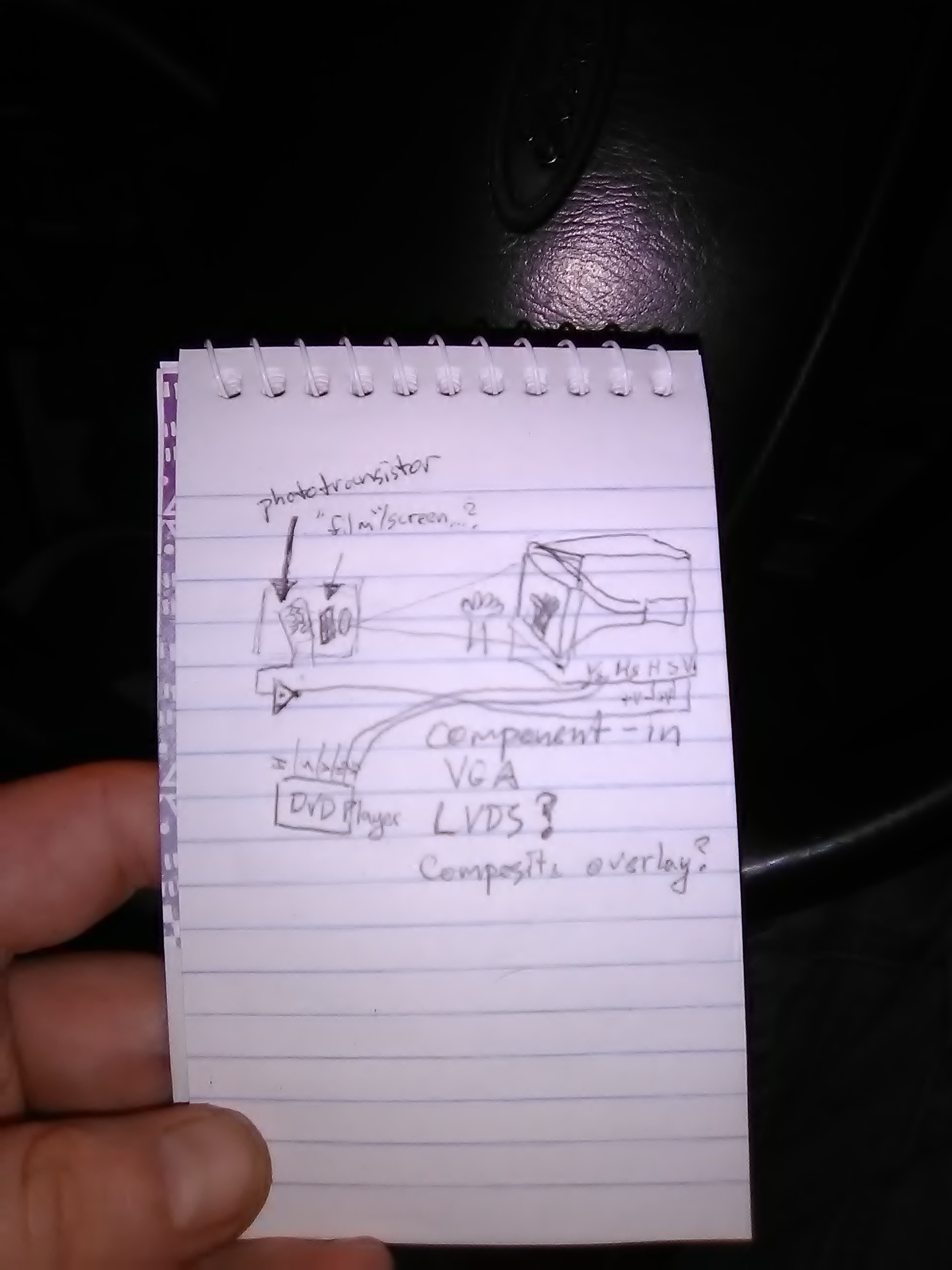
Turn your tv into a shadow camera
02/28/2020 at 02:04 • 0 comments![]()
sorta thing coulda been in MIMMs' books, Boy's Life, Popular Electronics, etc... Hard to goog, though.
Heh, wire up Hue and Sat, and a tiny bit more circuitry on Value/Intensity, and yah got a shadow-puppet blue/green-screen from the DVD!
Ah, CRT only... duh. *maybe* STN LCDs.
Also, record in realtime with yer vcr ;)
Inspired by:
https://hackaday.com/2020/02/27/recording-video-in-the-era-of-crts-the-video-camera-tube
Apparently, there is a scanner made from picture tubes [rather'n camera tubes] "Flying Spot Scanner" [see wikipedia].
-
Ferrofluid generator
02/05/2020 at 23:10 • 4 commentscapillary action - via plant illness
----
A ferrofluid siphon using capillary action, reservoir at the bottom, a siphon tube U-shaped [upside-down] to a receiving tank higher up; cap-action fills the tube, a magnet is exposed under the receiving tank to draw fluid out of the tube into the higher tank. When full, the magnet is blocked, a valve is opened to a separate pipe between the two tanks, with intermediate turbine.
Make electricity, profit. copyright me, 2-3-2020
-
Blue LED fades to teal/blue-green?!
01/12/2020 at 02:21 • 12 commentsUPDATES At bottom!
I NEED TO KNOW MORE!
This is a $1 Car->USB-power adapter. When powered, the LED is a piercing blue, but when power is removed, the capacitor discharges, I'm almost certain I see the blue LED CHANGE COLOR as it dims, from a piercing/pure blue to a "warm" blue-green/teal.
How can this be?! Isn't the wavelength dependent on the material?
If this LED were supplied with the same average voltage/current, but applied instantaneously via PWM, would it glow blue or teal? Is its color a factor of instantaneous voltage/current, or something to do with "warming up" like a filament bulb? Or is this just an illusion?
----
UPDATE;
In this second vid we have the blue->greenish LED now exposed without shining throug translucent housing, and another identical device which to my eyes does not green-shift at all. Oddly, the camera [and/or my phone-screen?] shows a distinct greenshift for that one. The original greenshifting one does, still, appear to my eyes to be doing-so.
I've a vague idea regarding a brief dropout of the switching regulator when power's removed that could cause a brief voltage-spike causing a green-shift that maybe latches until the power drains completely[?], but doesn't increase in brightness since it doesn't recharge the capacitor[?] More on that in comments, below.
Thanks for the thoughts, y'all! This is intriguing, maybe I'll get more sciencey about it!
-----
UPDATE 2
This article is mostly about white LEDs, but mentions wavelength-shift due to PWM duty-cycle [and concluding due to heat]. Could be relevant-ish, plausibly.
![]()
https://www.digikey.com/en/articles/techzone/2014/feb/led-color-shift-under-pwm-dimming
Though, that shift [toward blue, with decreasing duty-cycle/heat] is tiny compared to what I see.
I tried some experiments with a DVD as a prism of sorts. Hard to capture with the camera, but I'm surprised how wide the "spectral width", as to my eye it clearly looks to cover the whole range from green to blue. There's even yellow and red [though dim]. I really thought LEDs were quite a bit more narrow in their spectra.
Still pondering.
Also, still haven't found much regarding peak-wavelength vs. current, *except* in overcurrent conditions.
-
DASH STILL OPEN
12/23/2019 at 11:09 • 0 commentsheh
I decided I don't like LED lights on my xmas tree, so invested in regular ol' bulbs.... which needs either 120VAC or a lot of rewiring. Since the dash is still open, I tapped off the wiring to my repaired lighter-outlet. I'd, previously, run wire to the back for 12V... but it was powered by a dangling lighter-plug which has since been repurposed, so the wiring's run, but ends were cut.
It's taken quite a bit of brain-rewiring to get to the point where I'm using 120VAC extension-cords for wiring 12VDC, but, seriously, $1 gets yah a plug, three sockets, and 6ft of wire. Nevermind those plugs actually stay in the sockets [unlike lighter-plugs].
Not advised. But, functional.
And, every socket needed gives two spares. I mean how can yah beat it?
So now that nice warm glow of multicolored incandescents. I'm really fond of that blue. Much nicer, especially in a chilly van.
Remember when blue T1-3/4 LEDs came out? They were so dim you could barely see them in daylight at 30mA, and $6 a piece when they first appeared in the Mouser catalog! I was so thrilled I bought several, and somehow got so fixated on keeping stocked I never really noticed that the light from blue leds is, frankly, kinda ugly. Maybe it's the narrow spectrum?
But for xmas lights, there's something special about the blue bulbs. I dunno what it is, they're much darker than the other colors, but the bulb itself glows, and yet somehow that yellowish glow still shines through, but only directly at the filament.
I dunno, maybe just nostalgia, but lights in winter were always about making long cold nights not only brighter but also warmer.
I had some "warm white" LEDs on the tree, first. They seemed nice alone [*especially* in comparison to the cool-white], but beside the multicolor incandescents they have a very weird feel, almost ghostly. It feels like they're ejecting dust rather than emitting light.
---
LOL
And only *just now* it occurs to me I coulda left the inverter up front and actually ran those extension cords at 120VAC. Wow, brain. Wow.
-
Dash STILL open...
12/07/2019 at 19:30 • 0 commentsWouldn'tcha know it, the brand-new heater-fan switch is already failing!
Yesterday in the full-on position it was running about half-speed, which is actually faster than the other settings, and if I jiggled the knob just-right it would do full-speed.
Today, no full-speed. Oddly, I'd been thinking it'd be nice to change those resistors such that the distribution was more logical, specifically I wanted a setting close to 50%: e.g. before the new switch-fail, its speed settings seemed around 10%, 15%, 20%, and 100%. 100's too fast, sometimes, but 20's too slow.
So, was thinking different resistors to make it more like 10%, 20%, 50%, 100%.
Then, the next day, after thinking this, the new switch[?] started failing, giving me basically 50% where 100% used to be.
No joke.
Weird failure.
50%'s nice, though. So, I'm not particularly complaining, but it leaves some thoughts, aside from the obvious, which I'll ignore for the sake of science. [Especially being that this is easily the third time the heating system's failed-to-/almost/-desired-functionality within a day of my thinking it].
So, main concern: if it's running at, say, 50% where it was 100%, and 50% is not an option with the available resistors [presumably, the replacement fan motor has a lower winding-resistance than the original], that must mean there's resistance [or voltage-drop] somewhere in the 100% path. This resistance is new, AND jiggling the switch did, for a while, give nearer 100%, as well. So, logically, this resistance must be in the switch. No?
So, as we found with the last switch, even a tiny resistance in the contacts [as I couldn't tell much difference from 100% fan-blowage] was enough to produce so much heat as to melt the switch's plastic.
So, then, an even bigger resistance should cause even more heat, no?
P=VI, V=IR, P=IRI=I^2*R... hmm, maybe.
I dunno. And no guess as to what'd cause said resistance, anyhow... near-perfectly-distributed oxidation across a sliding/rotating switch-wiper's path? [Or on the wiper itself?]
Well, through what'd appear to be sheer dumb-luck, I now have that 50% fan-blowage and recirculation without AC running, just as I'd planned on implementing but didn't actually implement.
What when I want 100%, or AC, again? I dunno. The third case was bad-luck, I'd rather not recall it, though repair turned out to be quite cheaper than I expected, which, after two weeks in the cold, was quite nice "luck" indeed. 50-50, I guess.
-
Dash still open
11/30/2019 at 03:47 • 0 commentsfixed the lighter-outlet. Kinda proud-ish of how it turned out, but that'll likely never be seen, and I guess that'd be a good thing, meaning it got the job done. Still, it wound-up easily two full days' work. Two hours' wages [and a few hours searching?] Prb coulda replaced it with a higher quality new one. Or, yahknow, $5 at walmart.
AC is weird, still with a wire dangling out the hood and through the door to indicate when the pump's on [almost never]. Boggles the mind, defies the manual.
Next problem with Recirc: it sucks all the heat away from the feet! So, am debating putting a reverse-switch on the fan [50A DPDT?!] Will prb need a [big] relay, instead. And, I dunno if squirrel-cage fans [nevermind the duct-work] will really allow for reverse.
See, the prb with *not* using recirc is due to exhaust-intake while parked. So, it's kinda important for heat... or get a propane heater after payday. Or go south.
Radio Aux-in is great, but some-idiot used a short and delicate wire "temporarily." And, it makes a pretty decent 4G antenna in some orientations. So, shielded is the plan, and I've a ton of old inter-pcb wires from old VCRs. oddly, like CD-ROM audio cables, it's all left/right and a single shield. Guess L/R crosstalk is better than [short] ground-loops? Sure, why not. Also, presently, picks up the FM audio signal, a bit. I'm guessing shielded [insteada twisted-pair with ground] might help. Though still debating the best grounding scheme... one end unconnected? Oy! So, "temporary," until who knows when. Oh, also the brilliant idea to use RCA jacks... 'cause there's plenty of space for another huge hole. Gonna be ridiculously-placed, though functional.
And blower-switch seems OK, I even found a knob in my collection which *exactly* fit... and then lost it.
Weeee!
-
ISA PnP, now that's a hack!
11/06/2019 at 16:33 • 6 commentsMeh... wrote this a while-back, realized I got some details wrong, intended to fix 'em, but ah well. The jist's there.
-----
Always been a running-background-thought in the ol' noggin... how can ISA plug-and-play function on a bus which, by-design, requires each device to have a dedicated address?
A bus-transaction, simplified, consists of:
1) output the device-address
2) set-up the data-bus
(Hi-Z for read, or data to write)
3) strobe the /ReadData or /WriteData pin
Note that the order may vary, slightly, but is important! E.G. once that /WD signal comes through, the data and address *must* already be set-up, and remain for a while thereafter, otherwise you may write the wrong data and/or write the right data at the wrong address[es!]. Also note, there's no "non-address", every address, including 0x0000 and 0xffff [which may result from e.g. *not* explicitly setting an address, which can't actually be done], may have a device or memory attached.
Challenges:
A) Bus accesses are handled via hardware, with a very specific protocol. So, no bit-banging of certain pins, even if, in a typical access, that pin is only paid attention to while another is active.
B) Similarly, pnp devices should work in [older] systems which are not designed for it [the OS will configure the cards]. So, e.g. no turning output-only pins [like /RD, or Address bits] into inputs, or input-only pins like interrupts into outputs, etc. because older hardware just wasn't designed to do that.
C) There are some other signals, e.g. to allow the processor to release the bus to other "co-processors" such as an FPU or DMA controller. I suppose it might've been plausible to do pin-repurposing by e.g. a slight modification/upgrade to one of these, or even, e.g. releasing the bus to a new device [like an ISA card designed as a PnP-"host"], but, realistically, by the time PnP was becoming a thing, FPUs and DMA controllers were long-since embedded in the CPU and bridge chip. Further, the I/O logic buffers [or, more importantly, input-only or output-only logic buffers] for each pin on the ISA bus would've been in the bridge-chip on newer systems [or dedicated discrete logic on e.g. a PC/XT], between the FPU/DMA/CPU and ISA bus. So, again, changing the direction of a bus-buffer pin which was designed to be one-way [e.g. /RD, or INT] would not be possible even when the CPU releases the bus. So a theoretical "PnP-host" add-on card still wouldn't be able to e.g. turn /RD at the bridge into an input, nor, maybe, even Hi-Z. Thus, it'd still be driven by the bridge, even while the hypothetical PnP-host card attempts to do the same even, again, if the CPU were to release its control of the bus.
So, basically what I'm getting at is that the only way to access an ISA card is via a well-defined protocol which basically precludes any sort of pin-repurposing, bit-banging, etc.
[I'm sure there are more challenges, but I'm on a roll]
So, then, how can one configure a PnP device whose address has yet to be configured? How do you tell it you're talking to it?
Sure, it could just *listen* to every transaction, to/from every address, but how can it know [how/when to] respond or act upon whatever it "hears"?
And, further, how could this work in a system with *several* such devices. How can one be configured differently from the next? They don't even have the ability to respond, certainly can't talk directly to each other, and the system doesn't even know they're there!
And, further-still, in a system with *several more* non-PnP [nor even PnP-aware] devices which could literally be located at *any* address, and no defined protocol for identifying themselves, how are we to avoid conflict *during* configuration?
So, then, one might think "well, obviously, the first step is to at least get their attention," and that means some sort of signal sent via normal ISA bus transaction... and... whatever signal that may be, it can't cause havoc with other devices...
And, basically, as simplistic as it could be, they decided on a single common address for all PnP cards' configuration-registers. [Listen-only, so-far].
How'd they get away with *not* interfering with other non-PnP devices that might use that address?
[And, remember, the world of PC-compatibles is *much* larger and *much* more diverse than a mere home/office/gaming-rig... we're talking research and industry, CNC machines, etc. many with *very* custom ISA cards, maybe even one-of-a-kind. That company's heating system could exist at that same address!]
So how do they guarantee not interfering with heating systems? They don't. Simply.
They chose an address which happens to usually be used for another--at that point in time long-defined--purpose... Then set up a PnP-configuration protocol that, should that other non-PnP device exist [which it usually does], won't cause trouble with that particular device at that particular [conflicting] address.
So, they chose to use the parallel-port's status-register address for ISA-PnP configuration. Again, that means: every ISA-PnP card *and* the parallel port share the same address, initially/at-boot. And, here, by "share," I don't mean somehow each bus-transaction gets somehow distributed to the appropriate device. I mean that *all* these devices receive and process *all* transactions at that shared address.
This works-ish because *usually* A) the only non-PnP devices that *usually* use that address are parallel ports, B) the parallel port status-register is *usually* read-only [so, since wired as-such, a Write-access will have no effect on the parallel port], C) this PnP configuration-register, located on every ISA-PnP device, is *write-only*
... aside ...
Z) [I suppose] even if the parallel-port's status-register is Read/Write--e.g. a newer port design may write the status-register to configure newer modes like ECP--usually the printer/zip-drive/scanner driver is loaded long after ISA-PnP configuration, and thus the random junk left in the parallel-port's status[Read]/configuration[Write] register will most-likely be overwritten with the desired configuration later.
Again, there's a lot of presumption, here! Here's hoping said drivers don't rely on an expected boot-default configuration and/or use Read/Modify/Write! Or, maybe, the ISA-PnP system loads default values back to the parallel-port's status/configuration register when complete. Though, knowing a tiny bit about ECP, which basically treats the parallel port like a bus [with transaction protocols, like ISA or IDE, rather'n essentially bit-banged like old-school parports], it seems plausible certain random parallel-port configuration settings--set during the PnP-configuration scheme--could initiate transactions with parallel-attached devices, possibly leaving them in weird/unknown states! This is an aside, and I'm betting was probably considered in this choice of address.
But, another consideration goes for custom cards... hacking a parallel-port circuit is relatively easy, consisting mostly of 7400-series latches and buffers. E.G. original parallel cards were unidirectional, the data-pins output-only. Converting one of these cards to bidirectional required little more than cutting and rewiring the trace leading to the data-latch's /OutputEnable pin, thus allowing the data-latch to remove its data from the output pins so they could be driven by the device. [This was made extremely easy because the data pins had a read-back buffer attached already, for things like read-modify-write of the data in the output latch.] Now, doing a similar modification to the status-register would be nearly as simple. Piggybacking a 74374 latch onto the status-register latch chip would be an easy way to add an additional 8 outputs to the parallel port. In consideration of the amount of circuitry necessary to interface with the ISA bus [address decoders, etc], it seems almost likely such "hacks" would've been somewhat common practice for e.g. one-off industrial/heating/lighting controllers [nevermind hobbiests] where rewriting the software is no longer an option. And, now, upon upgrading to Win95, replacing the motherboard or flashing the BIOS with one that's PnP-aware, or installing an additional [now PnP] serial port, etc. there's a lengthy process during boot, and any time in the device-manager, flipping relays at speeds which could be damaging, and unknown values-written--and unchanged until the custom software is [re]loaded--running motors past limit-switches, and so-forth. I'm betting there were many affected who had no idea what was responsible.
Further, I'm pretty certain there existed some devices which intentionally used the parallel-port's register-interface, and likely extended it a bit [like the hypothetical one-off card described earlier], such as, maybe, GPIB cards with printers attached. So that the typical DOS print routines could be used with a much more sophisticated bus. In such a case, that read-only status-register would be a perfect place to add a configuration-register e.g. for the printer's GPIB address.
Suffice to say, the choice of address for writing the configuration-register seems a bit funky to me. though it may be one of the best-available choices.
[Note, also, the thought crossed my mind to use a *memory* address, rather than I/O; writing random values to an otherwise not-yet-used RAM location should have no effect on anything. There are several potential hurdles, here. A) the configuration process might occur at any time [even after the OS is loaded, as in Win9x's Detect-hardware, or a DOS driver for a PnP card], so finding an always-non-allocated memory address... well, that pretty much does-in that idea. B) in the era of fast RAM, it's entirely likely memory-accesses to actual RAM are intercepted by the bridge-chips, directed to the faster SIMMs and *not* directed to the slower ISA bus [also], as would've always been the case in older systems where every bus transaction was identical. C) cache could make it even more difficult! [Though, I think that can be disabled]. [But, then, it must be a pretty sophisticated routing system, as some memory-locations are explicitly used by the I/O system, such as the VGA frame-buffer... hmmm... is the original 640K *always* limited to ISA speeds?!]
... end aside ...
Anyhow, any write-transaction at that address gets all of the ISA-PnP cards' attentions.
From there, there's a "key" sent to, again, all of the ISA-PnP cards; a specific sequence of bytes sent to that same address. This confirms to the cards [all of them] that the system wants to start configuring them.
But, now, how does it configure *only one* card? [And, actually, "card" is inappropriate, as multi-function cards need multiple configurations].
So we need a bit more background. Yes, each card [or function?] has a unique [UNIQUE] identifier, including a 32-bit manufacturer ID, and a 32-bit unique ID [so, say you have two identical cards, they can be separately-identified].
Alright, but now how you gonna select the first one to configure? Test every single possible ID of the 2million-squared? Nah, booting would take forever.
So, yes, more background; there is an address *also* for read-back. BUT: this one's at a different location. Otherwise, reading-back from the shared parallel-port status-register and PnP configuration-register address *will* get a response from the parallel-port [when installed, which was *usually*], which would cause bus-contention with the PnP cards' also responding.
But Wait! The parallel-ports other registers are all R/W, so we can't use them! And there could be *anything* at *any* address!
So, they've got a *range* of addresses to choose from, for read-back. But, no, there's not yet a way to set a unique read-back address for each PnP device. It gets crazier.
After the "key" unlocks configuration-mode on *all* the devices, it first searches for available devices, and requests their IDs. In that request, it tells the devices which address to respond at.
Again, two problems: there may already be another non-PnP device there, and *all* PnP devices receive the same request-to-identify. Thus, multiple devices *will* all respond simultaneously on the same data bus at the same time. Contention-much?
This is by-design. (Wow!)
So, first, the system can detect whether a non-PnP device responds, because it's expecting responses in a very specific pattern. [More on that later]. If it detects data outside that pattern, then it knows a non-PnP device exists there, then retransmits the "ID request" telling the PnP devices [all of them, still] to respond at a different address. Repeat until an open address is found.
[And, I guess, no worries of damaging buffer-outputs when all the PnP devices drive the data bus at the same time as the non-PnP device?]
OK, now what?
Pattern, contention... right, so, this is as far as I've gotten in-detail, skimming the rest. So take the following with a grain of salt:
The "specific pattern" consists of, essentially, each ID-bit being sent one-at-a-time through the lowest data bit, each ID bit is requested sequentially. That means, for the first request, if bit0 of any card's ID is '1' then they simultaneously output that to the bus. When that's the case, any card whose ID's bit0 is '0' drops-out for the remaining sequence. Thus, the data-bus is driven by *all* ISA-PnP devices whose ID-bit0=1.
Now, I'm pretty sure I read that there's an open-collector scenario in here... not exactly sure how. And, actually, I vaguely recall something about the devices' encoding the ID-bit0 differently [maybe 0b01 for '0' and 0b10 for '1'?] But, again, if the data bus reads anything other than those two expected values, then the system knows there's a non-PnP device there, and starts over at a new address.
Where am I going with this? I wanted to breeze through these details because I wanted to make some point...
Oh yeah, after each ID bit is transmitted, and the lower-IDed devices "drop-out" then the remaining devices respond with 0x55 and 0xAA. I think, first, this identifies that, indeed, even if all cards' ID-bit is '0', that it should continue. This, too, helps to verify that there's not a non-PnP device at the response-address.
Then it does the process, again, for ID-bit1, and so-forth. After all 64 ID bits shift through [and 8 CRC bits], all but one device have "dropped out," and its ID is now known. It drops-out entirely, and the process repeats for the next device, and the next.
OK... now where was I going with all this?
Dunno.
It's a clever technique to add functionality to a bus not originally designed for such a task, the "upgrade" can be done entirely in software by any PC, needn't even require BIOS support.
Maybe "now that's a hack."
Maybe I'll find a PnP [8-bit?] card to throw at #Improbable AVR -> 8088 substitution for PC/XT .
today's assorted project ramble "grab-bag"
Assorted project-ideas/brainstorms/achievements, etc. Likely to contain thoughts that'd be better-organized into other project-pages