Eric Hertz
-
While Dash Open
11/03/2019 at 10:53 • 0 commentsFrom the last log, it started with a burnt heater-fan speed switch, yeah, it was gnarly.
The housing around the contacts/terminals crumbled out while exploring the damage.
I had bought that [the third] two winters ago, a cheap push-pull SPST on/off 20A switch, rather than the 4-position rotary-switch designed for the job. I wired it up so Off was the lowest speed-setting, which places three resistors in series with the motor and ground. On, then, was the highest speed, bypassing those resistors, wiring the motor straight to ground.
I almost, this time, bought a slightly higher-quality SPDT toggle-switch, 35A this time, which'd'a given three speeds... but, it would still be switching directly between essentially-off [low-speed] and full-speed... inductive arcing, much?
So I started thinking. Per chance, a few logs back i'd done some research on switch-contact-ratings, for another reason entirely, and one of the resounding factors in such ratings is *inductive loads*... like motors, which can cause arcing during switching that'll destroy the contacts' conductivity... so much a concern that, say, a 5A 120VAC switch is downrated to 5A at 14VDC (fourteen!). It's kinda a big concern!
Now, I dun have with me an ammeter capable of measuring the current-draw of my blower-motor... its fuse is 50A, and it just destroyed a 20A switch. And that after what looked to be a slightly-higher-quality-but-similar switch a couple years back, and *that* was a replacement for [I assume] the original factory-installed switch. Yesterday's purchase is *at least* the fourth.
So, more thinking... yahknow, they could reduce quite a bit of contact arcing, in this shorted-series-resistor arrangement, by using make-before-break switching... and that'd be comparatively trivial to do in... A Rotary Switch. [Like the original].
So, I coughed up the extra $17 for an aftermarket switch intended to replace the switch designed for the task, on a whim that said design mighta considered make-before-break, the intended current-draw, and likely more I hadn't'a thoughta... *and* on the whim that said aftermarketers followed-suit...
Well, sure-enough they did. It's actually more elegantly-simple, yet more fully-functional, than make-before-break; because we have tap-points at each resistor, they merely short the resistors that would otherwise be bypassed to ground.
So, like, the lowest speed-setting no contacts are shorted, all the resistors are in series to ground. The next speed-setting shorts the first tap-point to ground through the switch... But, of course, the resistors are near the motor *and* grounded there, and the switch and its ground are several feet away, so it's more like a small resistance in parallel to that first [small-resistance] resistor. Now the higher current through the motor has two paths, reducing the strain on the switch-contacts [and wires].
Then the same for the next speed-setting, now there are three paths for the even higher current.
It's a strange blend of cheap, lazy, and yet highly-effective in a way that regular "high quality" general-purpose switch-designs would be hard-pressed to mimic.
Take it a step further, the actual process of physically engaging contacts can wear them [and the bearing-surfaces, etc.] out, especially considering the surface-area necessary for such loads, but in this design each contact only makes/breaks once over the entire range!
Definitely worth the extra $17 for the learning-experience, alone. I can't vouch for the quality of this particular implementation, yet... Before I had the make-before-break idea, I was pretty turned-off at its being housed in plastic, being that overheated plastic was the problem at least twice before... OTOH, with the potential for much-larger contact-area, and the seeming solid single piece of formed metal all the way from the connectors to the wiper [rather'n, say, a connector riveted to the contacts], there's not nearly as much room for resistance to create heat in the first place. So, I guess we'll see.
---
And some updates on "Other while-dash-open ideas include" [from the last log]:
* 12V banana plugs, ferchrissakes.
* [Maybe 5V and-or built-in USB? + switch!]
* Heater only does recirc with AC running, by stupid design. Add AC cut-off switch
-- Actually, I fought this all day... eventually running an indicator light off the A/C compressor's clutch, and seeing nary a blink. Then hours of research trying to find a phantom relay and phantom schematics... turns out, the User's Manual says, A/C is *enabled* in most modes [including recirc and defrost], but only comes on when the ambient temperature is above "around" 43deg F... [sheesh, was it *that* cold all day?!] And, I *finally* found a schematic, which clearly shows the circuit, *including* the clutch, which is, actually, powered through the dash-switch, not a relay from some unknown pin on the computer... the other schematics showed only the switch signal [via intermediate sensors/cut-offs] going to the computer, no clutch to be found. Apparently the computer uses knowledge of the clutch's engagement [rather than knowledge of the switch/sensor-state] to adjust idle-speed, etc. [rather than turn on/off the clutch]. The new schematic actually explains this, *and* shows the clutch. Sheesh. After *hours* of deduction and research.
--Days later, surely it's been hotter than 43deg a few times... so far I've only seen the indicator-light blink briefly when I start the engine while recirc is on. For this season, that's great. Means I'm not cooling the warm cabin air [and using extra gas to do-so] before reheating it. Maximal heating. But, by-design, that method is also supposed to be used with defrost; cooling the air first causes condensation, which drips outside. It's a dehumidifier, by design. So, I haven't really needed dehumidification, so far, but it would seem it's not an option in the current state of things [which is weird, because just a week before installing the A/C clutch indicator, it was so dry I was getting zapped!]. Seems ridiculous to be even thinking about A/C these days, nevermind never having had it prior, nor expecting I ever would have it... but, apparently it can be something to consider, even in winter. So, I guess, there's something not-quite-right with my A/C system, but it's *mostly* favorable for now.
* Aux Lighter-outlet melted-to-short. replace!
-- Looked into this a bit, too. Shitty SHITTY design. I'm sorry. 20A has to go through a rounded-head held in place with a spring that tries to push the entire plug out, and they mount that contact on meltable plastic?! No, it gets worse. That contact is riveted to the connector, that rivet compresses two housings which has the ground-shell compressed [via meltable insulator, and a positive rivet] to the ground-connector. Positive contact melts through insulator, [luckily] shorts to ground-shell [blowing fuse], and the whole system basically self-destructs. If it went just a tiny bit differently, positive and ground wires would be exposed through various pieces of dangling metal and likely fall on any number of electronics behind the dash. Two bolts and a PCB-material washer should['ve] fix[ed]` the problem permanently.
* Surely more... blanking.
* Oh, stereo power-source selector-switch!
* Also might look into cleaning duct-work.
-- It's a start, anyhow!
* Still... surely more...?
-
AUX in!
10/31/2019 at 08:36 • 0 commentsHeater fan switch has been getting so hot as to fill the place with burnt-electronic-smell... it was probably bound to happen, the biggest switch I could find that day was 20A and the blower-fuse is 50(!)A. Also, inductive-loads, arcing, etc...
So ripped out the dashboard-cover at some late hour, and leaving it 'till payday for a better switch.
[Note to self: heat-selector-switch controls blower-relay, speed-switch *directly* switches in and out series resistors with plausibly 30A blower motor. This is the third failed switch. Maybe turn heat *off* before adjusting speed.]
[Also, obviously, thoughts on relays or even PWM.]
----
Meanwhile, a few long-running project-ideas for while the dash is open...
Hacked the cheap FM/AM-only stereo for AUX-in, can finally play my own tunes [and GPS directions]! [Yes, I have an FM transmitter. It sucks, and my phone's *really low* max volume made it far worse.]
Stereo was a bit quirky, I think it's Class-D, and apparently that means the two identical large-ish caps near the [speaker] connections *aren't* for the speakers. None of the chips have datasheets, wiring is crazy [rear speakers not implemented, so they ran front-right - signal trace to rear-right +, first, shorted that with rear-right -, then fed that to front-right - via two parallel 0-ohm resistors, and such-like.
Ultimately found two parallel traces with large series surface-mount caps originating under the tuner-circuitry's shield heading to unknown chip which is connected to both the presumed processor and the presumed amp, presumably for things like equalization.
Oddly, it has four parallel traces leaving it through four of the same series caps, to the amp. Prb also handles r/l and f/r balance... if f/r was implemented. But why bother with wiring caps to unused outputs? Or maybe it's differential, hmmmm... plausibly isolating amp power/gnd from the rest... hmmm...
Also oddly, amp looks identical [sans different markings] to the other chip with the big caps... am thinking it's for power.
So, it was a crap-shoot, but I tombstoned the caps and wired up the phone and, yep!
Managed *just enough* space for a dpdt switch [on-on-on, weeeeeeee!], and dangling a headphone plug, 'till I'm up near storage again.
LOTS of debate about how to shield... ultimately the sun was going down, losing light to work by, so decided on two twisted-pairs of wire for each r/l signal pair. All "shields" tied together at the chip's ground, but at the switch they're N/C.
The aux input is split kinda like a mini-plug to rca cable, each signal "shielded" with a twist, then the shields tied together at both ends [one at mini-plug, one at the switch] then a single ground-wire down to that same point on the chip. Trying to prevent r/l crosstalk...
But, sure-enough, with no source connected to aux, and volume-maxed it definitely picks up the radio... not sure if it's a shielding issue, or inside the switch, or...
But *WAAAAY* better than that FM transmitter, which was too quiet, staticky, and picked-up ignition-firing, and even worse when the phone was charging.
On that note, not sure what to do about charging simultaneously... definite ground-loop-ish issue, seems to pick up the dc converter's switching[?]
---
Other while-dash-open ideas include:
12V banana plugs, ferchrissakes.
[Maybe 5V and-or built-in USB? + switch!]
Heater only does recirc with AC running, by stupid design. Add AC cut-off switch
Aux Lighter-outlet melted-to-short. replace!
Surely more... blanking.
Oh, stereo power-source selector-switch!
Also might look into cleaning duct-work.
Still... surely more...?
-
toggle switch VA ratings, and On-On-On
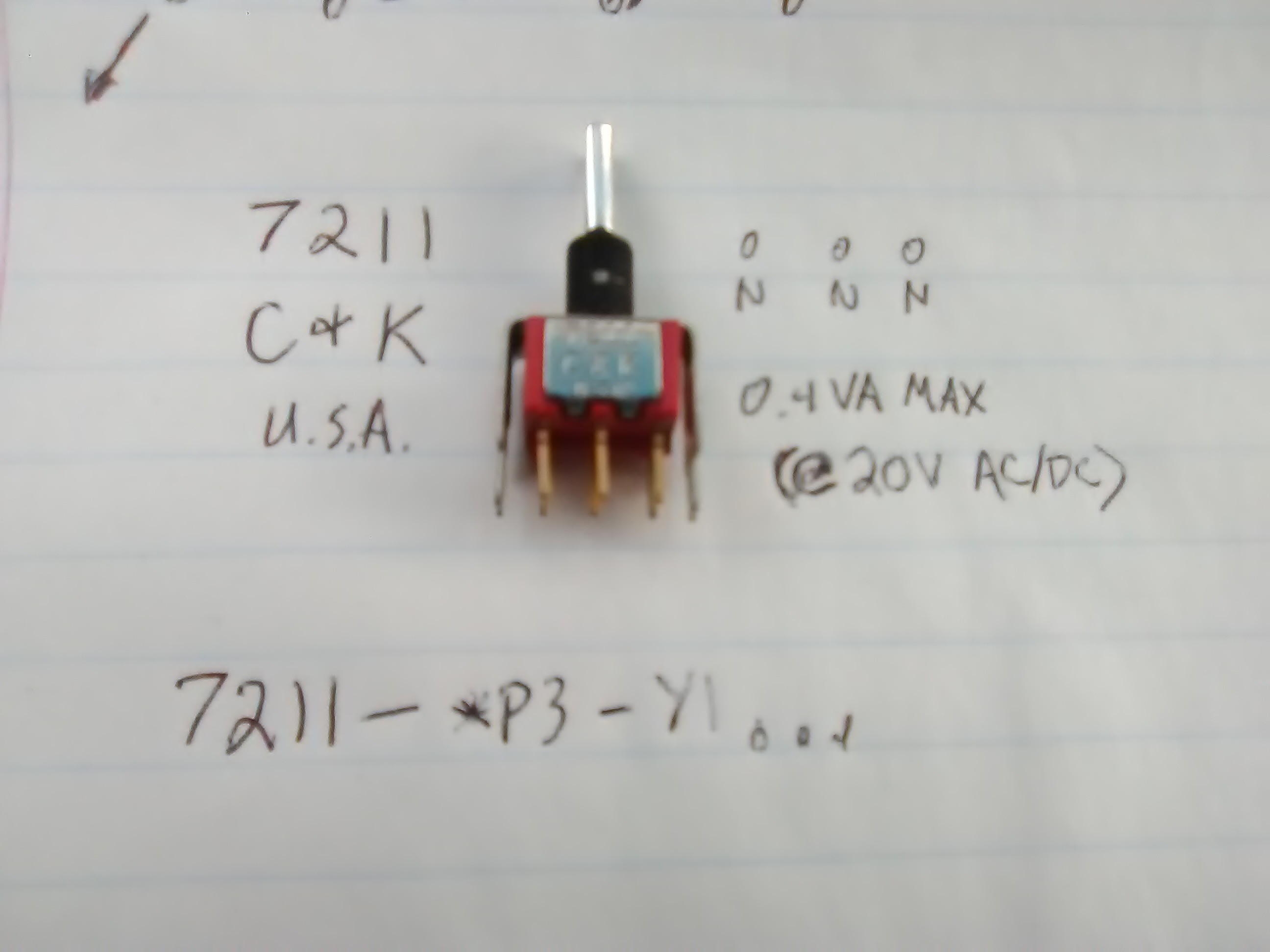
10/25/2019 at 19:22 • 3 commentsHave an interesting toggle-switch... pretty high quality, made in the USA, wound-up in my collection probably more than 20 years ago [I'm pretty sure I remember the day/person], and... it's still available new at regular suppliers. [This is the kinda quality design we're talking about].
![]()
C & K 7211.
Two odd things I never noticed about it in my previous uses, guess it didn't matter there:
A) On-On-On (DPDT, three positions, so what's with three Ons?!)
B) [Relevant to current project] "0.4VA MAX"
First-off, if VA means what I think it means, then this switch is no-go for my project. [And sure-enough, it would seem that way].
I had a bit of difficulty finding a decent explanation of this rating, so here's the best reference I found:
http://www.aeroelectric.com/articles/Switch_Ratings.pdf
Briefly: there are two common contact platings, gold and silver. Gold's used for low-power [logic], silver for high-power.
Silver oxidizes, so arcs caused by high-power switching burns off that oxidation. It's by-design! So silver-contacts aren't so great for low-power/non-arcing switching.
Meanwhile, such arcing would burn off the gold-plating on low-power contacts, and you'd be left with tin or copper [or something] contacts which make poorer contact than silver, and also oxidize and such.
So there you have it.
And, from the sounds of things, 0.4 VA MAX at <28V [20V AC or DC, per my datasheet] is pretty much standard for gold contacts...
And, yes, that does seem to be a measly 20mA at 20V = 0.4V*A = 0.4W. But it's a little more complicated than Watts, what with AC, RMS, peaks, etc. Or with DC and inductive loads [motors, or even long wires] and Capacitive loads [with large inrush currents, *during* switch-bounce!].
So, I guess the answer for my project is that, sure, this switch, if it had silver contacts, would handle 5A @250V [AC]... I thought it seemed pretty heavy-duty... And it'd probably do the job of switching 40VDC unlikely-max 3A [most-often a fraction] for a while even with bare copper or tin.. but probably not an ideal solution.
BTW look into that document, also, for info on derating for DC circuits [no zero-crossing = longer arcs] it's something like x Amps @ 120VAC -> x Amps @ 14VDC!
----
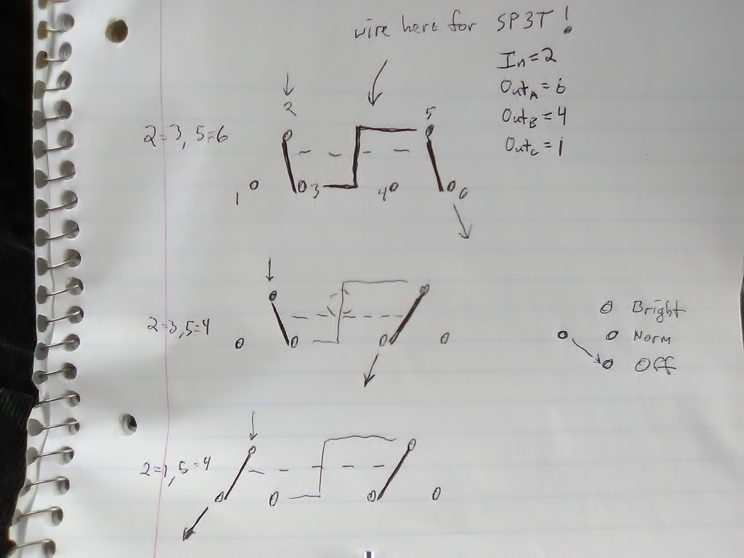
Oh, and finally, On-On-On, that's also nicely-covered in there. Basically it's like a typical three-position DPDT switch, but the middle position puts it in a weird-to-me state where the two poles are in opposite positions [What?!].
![]()
I once used these guys to drive/reverse the motors in a wired toy-car [hahaha 0.4VA my a**]. It worked... but now I see the middle-on was actually *braking* the motor [shorting its winding via one of the power rails]. Hadn't noticed. But, could be handy.
And, finally, they can be wired as a SP3T switch... cool!
which, also, makes for Off-On-On as a possibility [e.g. Off, Slow, Fast, or Off, Dim, Bright]
Whoda-thunk? Certainly wouldn'ta thought to look for such a switch, expecting it to be somewhat common!
-
Low voltage power distribution pt.2
10/24/2019 at 22:42 • 3 commentsOK, I think the conclusion is the renowned star-topology power-distribution idea, oft recommended in PCB design and system cabinets, is not really such a great idea if you've a floor-to-ceiling system cabinet and attempt to run power wires neatly.
Or, in this particular case, also not a great idea.
Which brings us back to the fancy thing [aka main selling-point, to me] about the DC converters I'm using: they've got isolated-outputs.
Thus:
A) all the voltage-converters can be powered by a single voltage source [a largish/heavyish bank of series batteries]
B) they can be located anywhere in the system [I'd like to keep the power-system as a single self-contained unit in the overall system. In part because this power-system is multi-purpose; this *particular* setup/use just happens to be the most complex]
C) as long as I run *one* device [rather, "endpoint"] off each converter, there's no concern of "ground" [or other power] "loops" [which, as detailed previously, can be quite a bit more gnarly than the audio-nuts' much-loathed "hum"]
The last point is key to the latest ramblings.
I'll drive the computer off a 15V supply, with a local 5V converter [am actually thinking two; a separate one for USB-powered devices, even though one 5V 6.8A converter should be plenty for both]. [These from scrapped car-usb-chargers rated for both 12 and 24V vehicle systems]. The computer is somewhat mobile, thus the 10ft power cable.
Then hard drives [e.g. backup, large/mass-storage, music, software installers, etc.] can be connected as-needed, minimizing cabling and power-consumption. Each of my IDE-to-USB converter-systems ultimately require 12V going directly to the drive [thus it should be pretty close to 12V, and somewhat stable]. Some have internal 5V converters, others do not. One has a 120V AC power-supply, that will be removed. I'll throw 12V-to-5V car-adapters in, as-needed. Thus, the drives will run off an *isolated* 12V output, again preventing drive/load-current from travelling/"looping" through the USB cables to/from the computer. Then, I'll do the "star" to these guys, as-needed, but keeping them close to the power-bank.
[Which suggests a wise choice may be a long-cord USB hub nearby... to-ponder].
I think that'll do it. There may be some looping between the 12V supply and the various drives through *two* USB cables... I guess these things we just don't worry about. [Seems odd to me]. Again, say one drive is sleeping, the other full-tilt, ~0A and 2A, say the power cables are two feet , even with beefy wire that could be 0.2V difference between "common" at one and at the other, now there's a third path between 'em through the USB cables, the system won't be happy with 0.2V between two different points in the "common" [nor 5V!!! COME BACK TO THIS] circuit, thus the running drive's load-current will actually be split between its main power cable and through the USB cables back down the sleeping drive's power cable. This still seems bad to me, and again, this setup is now hardly different than the ol' two-drive IDE setup in a full-tower PC. Weird.
"Come back to this": we have *another* problem, potentially, in the 5V system... were the drives' 5V coming from the same source endpoint [like common], we'd have the same issues with 5V as with common, since USB also carries 5V.
But, no, it may be even worse, now, as we have two separate converters essentially *fighting* each other *through* the USB cable!
Imagine one is trying to output 5.01V, the other 5.02V. And, again, imagine one drive runs at 2A, the other sleeps at ~0A... Seems *likely* one converter, plausibly the far one, will take the brunt of the load. Also seems plausible, in the opposite case, one converter will *sink* current, which most are not designed for.
...So, what...? Cut the 5V path in the USB system, maybe...? Fine, maybe even some hubs have diodes on the 5V line... Alternatively, run all drives off a single 5V converter [not ideal, more wires, bigger disconnects] [shit, this *also* applies to my two-converter system at the computer!]...
and again, what about common?
[I should probably note that a properly-designed USB device probably will take great pains in *not* driving VBUS with another 5V source... but I've seen countless designs where that's not the case. A typical example is a "bus-powered" 2.5in hdd enclosure, which uses two USB connectors [or USB and PS/2, in the early years] at the host-side for power, thus shorting VBUS on two ports... or, even more fun, when the signal connector is connected to the motherboard and the power-only connector is connected to a powered-hub, etc.! Thus, it's kinda hard to *rely* on a device's being properly-implemented when designing a system which might [likely] connect to devices which aren't... Weee! Of course, in my case, it's probably not a bad idea just to 'fix' any I might use regularly... and maybe a simple M-F connector with the VBUS not connected, for those I don't. Still, what about that ground? Nobody cares/d about noisy motor-current going through ribbon cables?!]
-
Low voltage power distribution?
10/22/2019 at 23:00 • 8 comments...is the best search term I've come up with, and still no relevant info...
So here's the deal: say I've got a multi-voltage DC power-supply ~10ft away from my equipment... the equipment consists of a [single-board] computer and various peripherals, all powered from that same supply.
Now, say the computer runs off 5V, it's connected to a hard disk which runs off 5V and 12V, and it's connected to the computer via USB.
Forget "ground loops", here we're talking *several* factors which could affect data, or even inject weird/negative voltages where they don't belong.
There's the obvious loop on the ground, around 25ft [10ft from the power supply to the computer, 10ft from the supply to the drive, 5ft between the drive and computer]. But, again, who cares about the audio-nuts' much-loathed "ground-loop" "hum" in a digital system?
Forget that for a second, let's look at the devices. The computer uses 3A max, but varies dramatically depending on CPU load. The hard disk's 5V is used only for digital stuff [I'm presuming], whereas the 12V is used for motors. Let's look only at the 5V system for now, and also presume that the disk's 5V load stays relatively small and somewhat constant.
Now, again, looking at the "ground" [or maybe more appropriately "common"] signal from *just* the perspective of the 5V loads, there will be different voltage-drops on those 10ft cables to the compy and drive. Say the drive uses half an amp at 5V, and say there's 1ohm in its 10ft connection to "common"... that leaves the drive's "common" [at the drive] at +0.5V relative to the power supply.
Now say the compy is asleep, and drawing only 0.1A, its "common" rests at 0.1V WRT the supply. Compy and disk are attached via 5ft USB cable; their "commons" also.
What happens, now? A USB cable, with its comparatively-thin wires [unless both sides' shields are connected to common, which is often the case], say 1ohm, has 0.4V across its common wire... it *should* not carry current [except in the case of a USB-powered device, but that's another matter], but V=IR, I=V/R=0.4/1=0.4A.
That's nearly *all* of the disk's circuitry current, travelling not through the disk's power wiring, but through the USB cable and back to the power-supply through compy's power cable.
Now, obviously this can't be the case... because those calcs rely on compy's common carrying 0.1A, and our result is that it's carrying 0.5A, etc. So, some balance must be achieved.
Let's assume, for a moment, somehow that balances to 0 current through the USB's common. [Note that I can't quite visualize how, in consideration of such scenario].
Now, consider the transients; a load changes suddenly, maybe compy's awakened to draw 2A, it will take time for the system to balance out, again. There will be a moment, however brief, where current [plausibly a lot] will flow through the USB cable's common. A surge of current [nevermind the voltage difference] through a long wire parallel to several others which are coupled inductively... a transformer, sending a surge of current through data lines.
Now, sure, maybe CRC-errors will result in data retransmission... but this is looking kinda ugly already, and we haven't even considered the 12V system of noisy power-hungry motors, etc. sharing that same "common," nor other large/varying loads such as a USB-powered DVD drive deriving its power through compy's power cables. Further, we haven't considered nearly identical effects on the 5V "loop," nor external interference/"hum" commonly-associated with "ground" loops [that could just-as-well occur on a 5V loop].
So far we have reasonable potential for data-voltages that, at least, aren't within high/low voltage tolerances for data transmission. It's also plausible such signals may *exceed* input-specs. I.E. If the drive's 5V circuitry's "common" is at 0.4V higher than compy's, and it outputs a 5V data signal, compy will see a 5.4V input. And the reverse, compy might output a 0V data signal, which will be -0.4V into the drive's circuitry.
And all this is only in consideration of *inter*-system data communication. What about the effects of a 5V digital circuit's *power rails* fluctuating so dramatically?
And, of course, there's plenty of room for our 5V source wires to also drop those same voltages due to the same length and wire-resistance... 0.5V on the drive's circuitry's "common" *and* 0.5V on its 5V wires, resulting in only 4V for the circuitry. [This is where remote-voltage-sense is appropriate, but can't do that with multiple endpoints!]
These values may seem extreme, but we are talking *amps* of current, non-negligible load fluctuations, and long wires.
It's almost a wonder a typical full-tower PC can even keep things straight with various drives and multiple endpoints, floppy and IDE cables with interconnected commons looping all over the place, motor-currents [however briefly] surging through ribbon cables with alternating data wires.
I'm a bit baffled as to how to best go about powering these devices. Almost thinking it best to just send 12V to each and have a local 5V regulator. But even still the long "common" wires, USB cables, voltage offsets, etc.
Oh, and I meant to go further into thoughts on the overall "balance" of the system. I'm almost certain it involves current through the USB cable's power wires, maybe even a lot, even in steady-state. Am somewhat convinced it may wind-up that the two long power cables both carry pretty much the same current, regardless of the endpoints' different needs. Then the USB cable must handle that balancing, so compy running full-tilt at 3A while the disk is sleeping means 1.5A through a measly usb-cable? And, further, reversed in direction... 1.5A *leaving* compy's "common," through the USB cable, *to* the device... I'm not liking this.
-
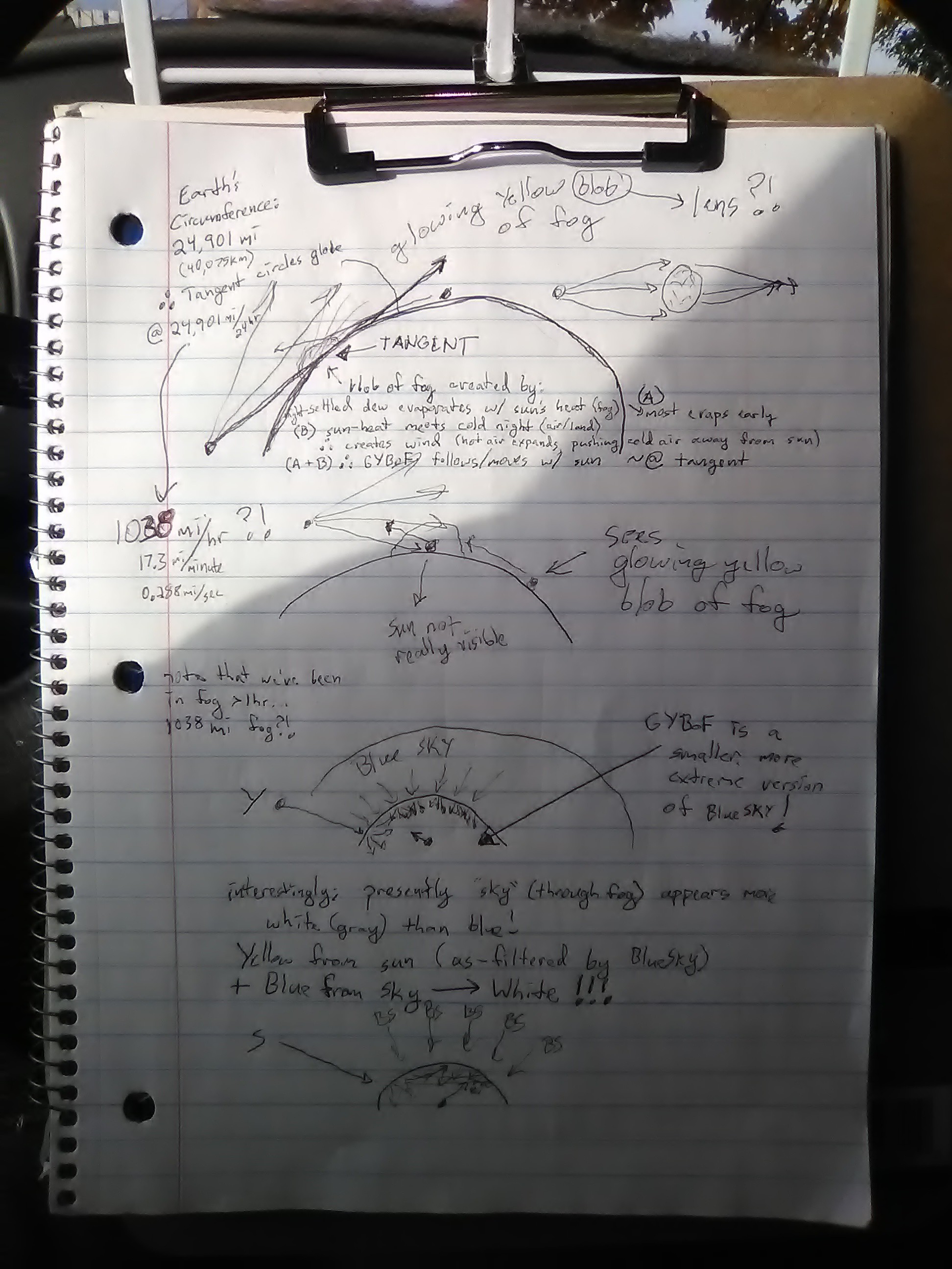
Why doesn't wind reach 1038mph?
10/09/2019 at 15:50 • 9 commentsweird thought:
A) wind is caused by hot-air meeting cool air. Presumably, the less-dense hot air pushes the denser cooler air.
B) the sun reaches the surface of the earth each morning, at a rate of 1038mi/hr
C) the night-air is cooler than that which is heated by the sun
Then: there should be a constant east-west wind following the sun's reaching the planet's surface, at 1038mph!
Flat Earthers Unite!
![]()
(Arising from thoughts on why pre-sunrise the sky was clear, but during sunrise we were engulfed in fog)
-
dummy-load power recovery 3
09/23/2019 at 21:25 • 0 commentsdecided to try paralleling the load-recovery "source" voltage with the batteries. There's a bit to consider.
For one thing, we've got a flyback inductor releasing power back to the input. At a 0.6A@5V dummy-load, that's 3W... But, of course, the, say 90%-efficient, converter needing loading is driven from a 40V battery-source, and thus the current going into that converter is much less than going out. 3.3W, 40V in, 3W, 5V out, so, roughly 0.6/8, less than 100mA.
So, now, we charge up an inductor from its 5V output at, say, 1A [because we need a 0.6A average load, but some of the time will be spent with the inductor discharging]. Now, when discharging the inductor we need to dump 1A as quickly as possible. But it's discharging back into the converter's input, which is far less than 1A, more like 100mA.
So, the thought, then, is to dump the majority of that current into charging a capacitor, then since the converter's input-range is 36-75V, that capacitor can charge to 75V. But, of course, this isn't free-energy, so once the capacitor's charged-up, it will begin to discharge, during that whole process dumping roughly 2.4W [assuming my circuit is 80% efficient] into the converter. But the converter needs 3.3W, so the inductor/capacitor obviously can't power the converter continuously. Once the cap discharges to 40V, the batteries take over.
Meanwhile, the inductor's being charged back up to 1A, and the cycle will repeat.
Now, all those numbers are rough guesses, and I've never designed something like this before, so it's coming on time to simulate. [And I don't have a clue how to calculate the necessary inductor/capacitor requirements] Like... how do I assure the cap doesn't exceed 75V, but that all our input power also goes out? Or, worse, how can this whole thing be properly-timed such that our inductor-charging and discharging times work, as well as the capacitor discharge time?
so, I thought an easy test would begin with falstad's simulator, best thing I could find for simulating the 3.3W converter input is an ideal voltage-controlled current source. P=VI, right? Nah, I=P/V, and it *really* wants to try V=0. So, now I've a bit to learn about the tools.
Ultimately, the point of the project, which led to this tangent, is to have a reliable and long-term power-source for my computer, among other things, so continuing down this tangent is a bit chicken/egg. That simulation's going to take some time to setup, meaning some time on the computer, which needs power. The 0.6A minimum load, realistically, is probably not a necessary concern to get this thing running.
-
Minimum load recovery pt.2
09/19/2019 at 21:48 • 0 commentsDon't put the load-recovery circuit in series with the input.
Quick estimates, assuming the DC converter's 90% efficient and the load-recovery converter is 80% efficient look pretty great. We can turn our 0.6A@5V=3W minimum load into only 0.93W load on the batteries!
But putting the load-recovery circuit in series with the batteries... well, here's a quick thought to get er goin': 80% of 3W is 2.4W. And a 90% efficient DC converter will draw 3.33W to make that 3W [to then make that 2.4W].
So now we have a 2.4W source in series with our 40V's worth of batteries... and the sum total is 3.33W, meaning the batteries are only outputting 0.93W! Great!
But P=VI, and since the sources are in series the current through our 40V batteries [at 0.93W] is the same as the current through our load-recovery voltage-source [at 2.4W]. Again, P=VI, I is constant for both sources, P is comparatively huge from our load-recovery voltage-source, so then V of that voltage-source must also be comparatively huge... to the tune of 103V, on top of the 40V. These DC converters have a wide input range, but nowhere near *that* wide.
So, parallel's probably the way to go, but it seems a bit risky to directly-parallel DC-converter outputs [again, the battery packs are 3.7V with a 5V boost converter]. And then it seems a bit goofy to insert e.g. diodes or resistors... they'll add to the losses we're trying to recover [and likely still, even when the real load is on and the dummy load disabled]. But, may still be worth considering.
...
And, it's kinda an interesting circuit I've come up with to do this... essentially a boost-converter whose feedback node is on the opposite side, measuring/maintaining input *current* rather'n output voltage [or current]. For my first attempt at a homebrew DC-converter, this'd be a doozy!
-
Minimum load recovery
09/15/2019 at 05:53 • 2 commentsThoughts on a switching dummy load, for a DC-converter, which redirects power back to the input.
At a minimum load of 0.6A, we're talking 20.4W just to power the thing with no useful load attached!
These are floating-output converters with a wide input voltage range, which, I'm pretty sure, means, if done right, the outputs can actually be placed in series with the input.
No, we're not talking free-energy, here... we're talking recovery of otherwise burnt energy.
Though, I've also pondered this same output-in-series-with-input to maintain the minimum input voltage while, say, half the series batteries are removed from the circuit for charging.
Weird world.
Oh, and this dummy-load would also decrease as the actual load increases.
----
And then *really* vague thoughts on using a similar technique, and the scaling necessary, to replace resistors in many general cases. Please send me some moolah and some credit if you steal this idea!
today's assorted project ramble "grab-bag"
Assorted project-ideas/brainstorms/achievements, etc. Likely to contain thoughts that'd be better-organized into other project-pages