"I should put a 12V lighter-outlet in this thing..."
Waitaminute.... one of the main points is that there are some things I don't want on a randomly-self-ejecting nor easily-bumped power plug.
[Of course, that'd've been easily resolved with in-dash banana jacks, which somehow hadn't occurred to me until weeks into this project]
And, of course this bright idea came from... "how should I connect [the thing that needs a reliable power connection]?"
But I think I have come to some pretty decent design-plans, many of which differ dramatically from my original goals.
E.G. I was planning to have two 5V 6A outputs, one for running my itty bitty computer, another for [USB, mostly] peripherals. But now I'm thinking of one 12V 6A run to the computer and two 5V6A dc-converters inside. Then I'll also have 12V available for peripherals, and only one long cable. And the 12V source has sense-lines, so 12ft later 12V should still be pretty clean.
Now debating cabling... am kinda low-budget and mostly trying to work with things nearby... Am thinking ethernet cable with pairs combined at each end for power, and sense lines on another twisted pair. Debating the fourth pair. And something about twisted-power-pairs [nevermind three pairs in parallel tied together at the ends] doesn't seem right to me... inductance? And large, plausibly somewhat largely-varying, currents in opposite directions through a 12ft transformer?
Meh... even though the AWG/Current tables are "very very conservative", a 0.5A per wire rating is nowhere near the 2A that'd be on each, if I used 3... so, some reality-check... 2.5ohms/100ft is 0.25ohms at 10ft [doubled, current out and return]... if I used a single wire for each, that'd be a 3V drop! So, even with three wires, each, still a volt. I guess not so bad, but still those other concerns. [And where's 12W of heat go? And, yeah, most ethernet cable is pretty stiff...]. But 4 beefy wires seems goofy, where yah gonna find two beefy and two thin in a bundle?
...
Then again, use beefy-enough wire, and is *remote*-sense really necessary?
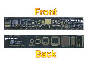
Hard to tell what's all on it from the tiny picture, but handy tool, potential business-card, and just a tiny bit more design effort and a pair of tinsnips, or a utility-knife and table-edge, or snap-perforation, could make it quite useful for prototyping, as well.
It really seems to me there must be ways to make transistors with household supplies/tools... yahknow, without a microscope or nasty chemicals or special oven or, most importantly, pre-fab semiconductor-materials like silicon wafers. Here's where my research led...
Metal rectifiers consist of washer-like discs of different metals, ...copper (with an oxidelayer to provide the rectification) ... interspersed with aluminium discs (which were often of a larger size, to provide cooling).
The principle of operation of a metal rectifier is related to modern semiconductor rectifiers (Schottky diodes and p–n diodes), but somewhat more complex. copper oxide [is a] semiconductor, in practice doped by impurities during manufacture
"In the history of semiconductor physics, Cu2O is one of the most studied materials, and many experimental semiconductor applications have been demonstrated first in this material:
Shockley's research team initially attempted to build a working FET, by trying to modulate the conductivity of a semiconductor, but they were unsuccessful, mainly due to problems with the surface states, the dangling bond, and the germanium and copper compound materials. In the course of trying to understand the mysterious reasons behind their failure to build a working FET, this led them to instead invent the bipolar point-contact and junction transistors.
Hah! So mosfets were the goal in the first-place! Then failing that, the bjt was born as essentially a mistake... then twentyish years later the technology existed for the *original* goal.
The problem with the realization of a working metal-insulator-semiconductor (MIS) field-effect transistor (FET) is the interface between the semiconductor and the insulating dielectric. This was obviously also the case with the experiments on the semiconductor cuprous oxide (Cu2OCu2O), which was historically used as a rectifier. John Bardeen (double Nobel prize winner in Physics) found that this problem is caused by interface states at the insulator/semiconductor interface which hinder the penetration of the electric field into the semiconductor thus preventing the modulation of a mobile charge layer (conducting channel) near the surface necessary for the field effect transistor. In the course of the experimental investigation of this problem with conducting probes on the semiconductor surface (germanium), Bardeen together with Brattain serenpitously discovered the bipolar transistor effect which led to the realization of the point contact bipolar transistor and later the junction bipolar transistor. Very few insulator/semiconductor interfaces have low enough interface state densities to be suited for a field effect transistor. Only in 1960 the first operating MISFET was demonstrated by John Atalla and Dawson Kahng. This FET, a metal-oxide-semicondoctor field effect transistor (MOSFET), used a specially prepared film on silicon () to obtain an interface with very low interface state density.
Visit his site, look around for parts 2 and 3, in which he develops electrolytic diodes with baking powder, aluminum foil, copper, and water, and uses them to decode a 7-seg display!
Then search for "electrolytic transistor" and prepare to brainstorm.
Also, check this out, creating audio from electrochemical reactions:
ok, so now there's 40V worth of batteries in series... that's 8 batteries need charging. And, in the last post I explained many hurdles.
Check this... the DC converters require 36V-min [74 max]... so 40V gives just enough clearance such that my 12V car system can bypass and charge three at a time, leaving 5 totalling 25V + 12V from the car = 37V to keep my loads powered while charging.
That comes at a slight penalty; now there's not quite as much available maximum power [max current is 2A, but now the voltage has dropped while charging]. Probably not a big deal, really... how often is 37V*2A=74W not going to be enough?
But, more frustratingly, it means a full charge requires three cycles, 3 batteries each, twice, and two in the last cycle.
[Hmm, I haven't yet pondered whether they can all be charged simultaneously if the system's not powering a load... 5V 8*2=16A might be a bit to consider].
OK, anyhow, the idea is simply use a double-pole/double-throw relay for each battery to switch it out of series for the circuit and into parallel for charging, and a diode on the 12V source and another on the last battery in the group handles bypassing.
Now, if I use that same logic with Even Moar Batteries, we can cut it down to two charging cycles. e.g. 60V cut in half + 12V = 42V > 36V. Now I only need two diodes [less power dissipation], and can charge the whole thing faster, six batts at a time... and I happen to have two 12V->5V 6.8A 'lighter' adapters, which can each charge three of these. And, of course, more runtime, and more max power when not charging.
[maybe 10's more reasonable? 25+12=37, although that might require bigger caps, again, hmm... maybe 14! Heck, 74/5=... sure, 15, why not?]
[BTW, this is getting a bit ridiculous, originally I just planned for rechargeable power for/attached-to a few things like a portable DVD player and TV [4G is expensive, yo!] and the little computer my buddy @Starhawk built me, oh and maybe a reliable power-source for my external backup-hard-drive... and then maybe for my electronics-projects when coding [e.g. #Floppy-bird is still in the noggin'], and then my electronics-projects which needn't coding [e.g. #Incandescent RAM is bubbling up again], and then, maybe the soldering-iron... and... well, it's starting to make a heck of a lot of sense to keep all that power centralized, I see, now, rather'n having a dozen devices each with its own battery[pack], especially since most are not likely to be used simultaneously].
Now, we still have the problems when I might bump the power-cord outta the lighter-plug, of: batteries which are charging take a quarter-second to turn-on for a load, combined-with: now there's switching time for the relays to put them back in series. So, back to a big ol' cap... two, maybe. But, check this: because our charging-bypass-voltage [12V] is lower than the total voltage of the bypassed batteries, charging the capacitor to the battery-voltage from 12V will *be* the load which will turn on the batteries. So, now, we needn't wait for the capacitor voltage to drop *before* the batteries know to turn on. Thus.... faster start-up. Of course, counteracted a bit by switching relays. But ah well. Besides, now we're talking 12 [maybe one less per charging-bank] relays, anyhow... 's not like we hadn't reached ridiculous-territory long ago.
[Of course, a reasonable electronics-hacker surely would just install banana plugs in the dashboard and be done with flaky connectors altogether! But there's always portability and dead starter-batts as good reason for this project]
Relays, yep... break-before-make, yo! [I may reconsider mosfets... but *four* vs one relay?]
The not-so-easy part of using all these usb-batteries in series is charging. That's most of half a spiral notebook...
These aren't simply batteries, they're batteries with a built-in charge-controller on the input and boost converter on the output. [4 terminals!]
If you thought charging regular batteries in series was difficult or prone to over-charging one while undercharging another, I challenge you to consider what happens with two series charge-controllers when one battery completes its cycle before another. Where's all that series current gonna go? What's gonna keep it dropping 5V?
Then, to make matters more complex, I really woulda preferred being able run the load off the car-power/batt/alternator *while* charging. No prob, the USB-batts have a 'bypass' mode, putting the input 5V on the output while charging [except, they actually disabled that feature, probably due to current-handling ability either on the charging/output circuit, or in consideration someone might try to charge it and an attached phone at 4A from a 2A port, so you gotta take ground from the input-terminal for both input and output]. And... in series, that means needing separate 5V supplies, put in series, to charge and handle the loads of the now charging batteries in series. Whew!
But, more difficult is switching from charging to output... [e.g. if i bump the car-plug] the batteries are actually 3.75V, the output is 5V, that means a boost-converter at the output. It takes about a quarter-second to turn on. That means a quarter-second "blackout" when the car power is unplugged. At 5V 2A I calculated needing a 0.1Farad power-cap to prevent blackout.
But then it gets even more complicated! The batteries switch to output-mode by detecting a current-draw... if a big ol' cap was put in parallel to the batt when it's off, the *cap* will handle the current-draw until it reaches 3.75V, or slightly lower, then some current will be drawn from the batt, telling it to switch on, then another quarter-second until it's outputting 5V. But, as far as I can tell, it's not 3.75V *direct* from the batt, but 3.75V through a high-value resistor. Then the cap voltage may well drop quite a bit lower than 3.75V by the time the 5V switches on. WHEW!
I've come up with countless possible solutions for charging, outputting while charging, and outputting without brownout when external power's disconnected, mostly relying on switching them from series-for-output to parallel-for-charging. [That's a lot of switches/relays/fets, and considerations regarding make-before-break, or vice-versa. And the extra time switching.] I've also pondered a few gnarly-hacks, like using two daisy-chained *non*-floating DC-converters [which allegedly don't like sinking current, but *might* actually be capable, since they have both high-side and low-side mosfets, a feedback path, and PWM-control].
Oh yeah, it gets even better! ... erm, what was it...?
...
Then these floating-output converters came my way... So, dig this... I can "boot" the system from 8x5V batteries, 40V. Then, because the 40V->5V converters' outputs are isolated, and because the batts can charge and output [bypass] at the same time, the 5V from the floating-output converter can be used to charge one of the batts *and* maintain the 40V source it needs in order to create that 5V in the first place!
It's not free-energy, of course, the power going into charging that batt will be coming from the other batts [at 1/7th the charge, each]. But, now, again, because the system itself is floating [entirely battery-powered] I can *also* bypass two [maybe three] [and possibly also charge] batteries by powering *anywhere* in the battery-chain from the car.
So, now, 3/7ths of the charge-power is coming from my alternator, 4/7ths from 4 other batteries, which, after, can be fully-charged by depleting the recently-charged batteries by 1/7th charge... or something, here's where it gets a little vague. But, the interesting bit to continue pondering is that the system can be used to charge itself... as yet another tool in the charging-solution... and, doing-so, now we only need a single 10,000uF [40V] capacitor to prevent brownout, even for 40V 2A [?!]. And much much more!
So, it's no longer about using the car to power everything, then having a battery-backup/UPS sorta thing, but now about having a completely portable power-supply which can also be charged while in use.
....
Oh, that other thing... what was it? Oh yeah, the other issue with using these like a backup-battery was trying to *remove* that power-up time, altogether... Then, e.g. a simple diode could direct power as-needed. E.G. with 10V's worth of batteries, through a diode to the load's positive rail, which can also be directly connected to 12V.... then there's no load on the batts when powered externally, then if I bump the 12V lighter-plug, it'd start immediately drawing current from the 10V battery-supply. Great idea with normal batts, more difficult with start-up-times and brownouts. So, then, the idea became how to keep the batteries "on" even though the load is coming from the car...
Wherein I designed my very first 555 circuit [oh, sure, I've *used* 'em, but never *designed* one from the standpoint of understanding how that mysterious 8-pin black-box functions. BTW look at ST's datasheet, best I found, showing the internal structure using a two-point voltage-divider with three 5k resistors, two comparators, a RS-latch, and an NPN transistor. That coupled with info on which RS-latch inputs take priority makes designing with the thing almost intuitive!]. This circuit was designed to first prevent flow from the 12V source, when initially powered, thus turning on the batteries, then, once the batteries are on, the 12V source is switched-in... a few seconds later the 12V source is switched-off, until current is detected to be flowing from the battery [which might be a little while, and unpredictably, depending on the load, since it would output 10V through a diode, which means the capacitor would have to discharge from 12 to 9.4V first]. Then, after current's detected to be flowing from the battery, it'll switch back to the 12V source again for a few seconds. Thus, the battery wouldn't go into 'sleep,' as a minimal amount of current would be drawn periodically to keep it awake. Hey, how does one measure a positive current-flow [through a diode]? A comparator! And lo and behold that's exactly what's at several inputs of the once-mysterious-to-me 555. Weee! Oh, and, since it uses cutting the current-flow from the external source to keep-awake, it inherently handles the case where I might bump the external source outta its socket.
But, that, keep-awake, is not necessary with the new system, since its purpose is to run the load off a comparatively-huge battery-bank at all times, which just happens to be incrementally-chargeable while in-use. 80W, 2hr... 40W 4hr, and so-on should be plenty for most my needs.
Been working quite a bit, for weeks now, on trying to figure out the best way to make-use of a literal stack of USB battery-packs I got for a steal...
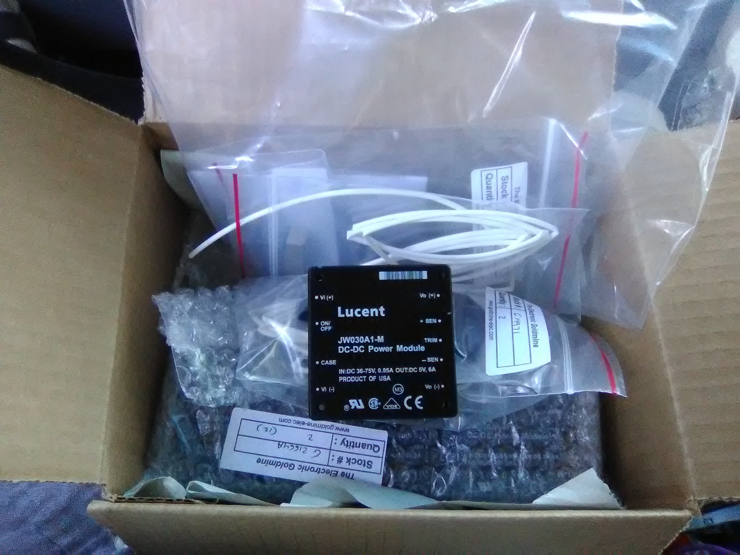
I haven't the energy to go into the details of half a spiral-notebook's worth of thoughts, right now, but the basic conclusion is to put them all in series for 40V 2A [80W for two hours!] And use a bunch of DC-DC converters to make it basically a multipurpose portable power-supply. I lucked[?] on a steal for 12 floating/isolated-output 5V 6A buck-converters for the cost of a couple meals at a drive-thru. No joke. These ain't yer no-name-brand modules, either, we're talking any one of these would easily be worth what I paid for all of them, even used. We're talking the sorta devices used to power servers with multiple redundant slide-out power supplies each attached to a dedicated UPS. We're talking... surplus is awesome.
Did I mention isolated-outputs? That means you can put all the inputs in parallel [40V] and the outputs in any series configuration you can think of. And they're [slightly] adjustable, so three in series, set to 4V will give 12V@6A.
So, wow!
Wasn't exactly planning to put *all* may battery-packs "in one basket," but this could be quite the tool.
----
Today I was diggin' the radio... rare I wanna keep listening to the same station for two+ songs after I park...
Occurred to me it wouldn't be difficult to tap into the "accessories" wire from the key-switch, and run the stereo [and more] off the new power-bank.
 Eric Hertz