-
[NEWS] Jetson Nano and Arduino Code
12/21/2019 at 09:29 • 2 commentsHere are some news of the project, for now IMU calibration is paused, I have been mainly working to set ROS on the SBC.
SBC
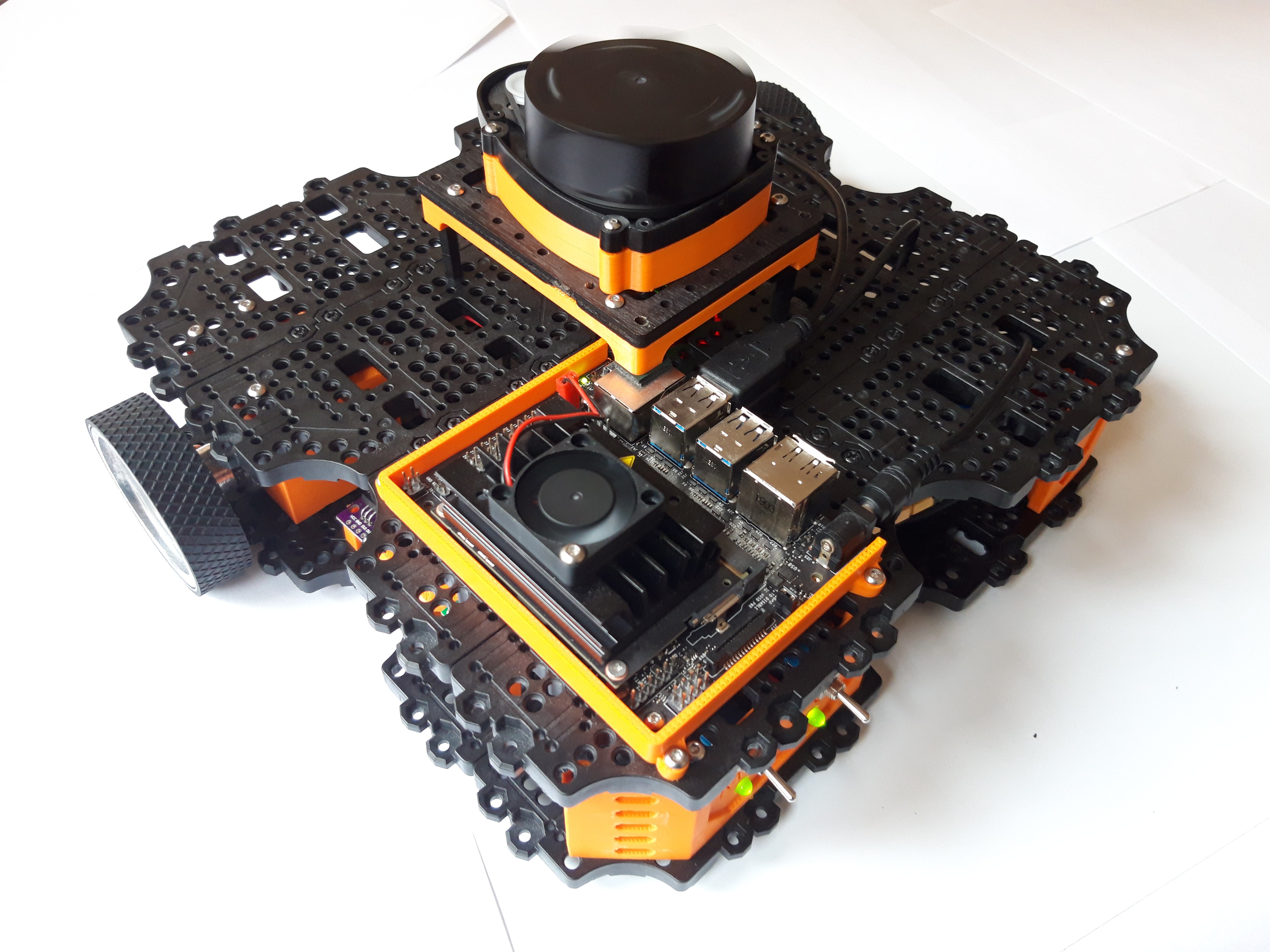
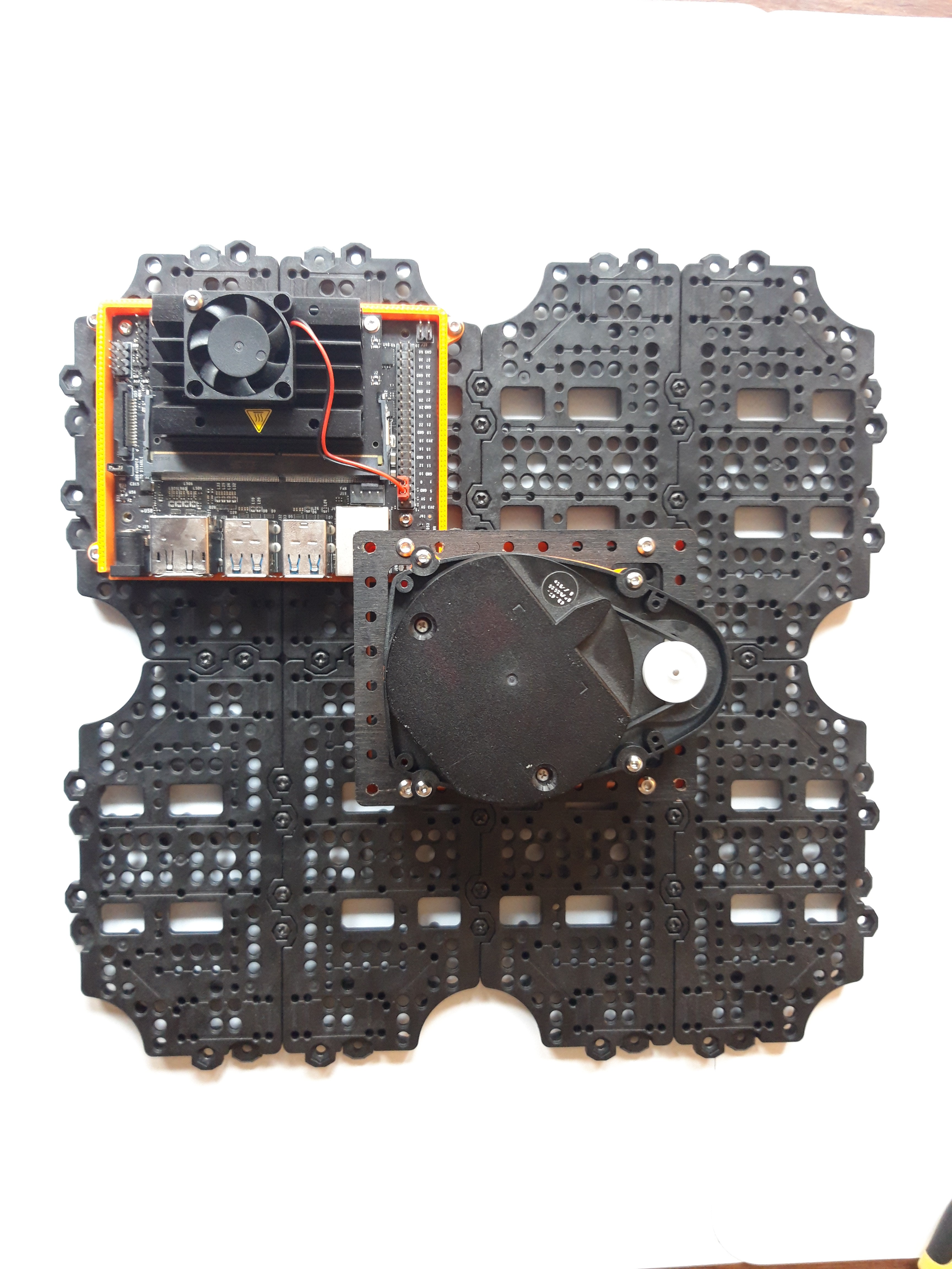
The one I chose is the popular Jetson Nano from Nvidia, which offers a powerful CPU/GPU in a small form factor. It doesn't include WIFI chip by default, so you need to choose one, mine is something like TPLink WN822N, I am totally not able to know if it's a choice or not. The Jetson is mounted on the upper plate.
Jetson Nano comes with a specific OS based on Ubuntu 18.04, it includes precompiled libraries using the onboard GPU. I installed ROS on it and set the rosserial communication with the Arduino Due.

LIDAR
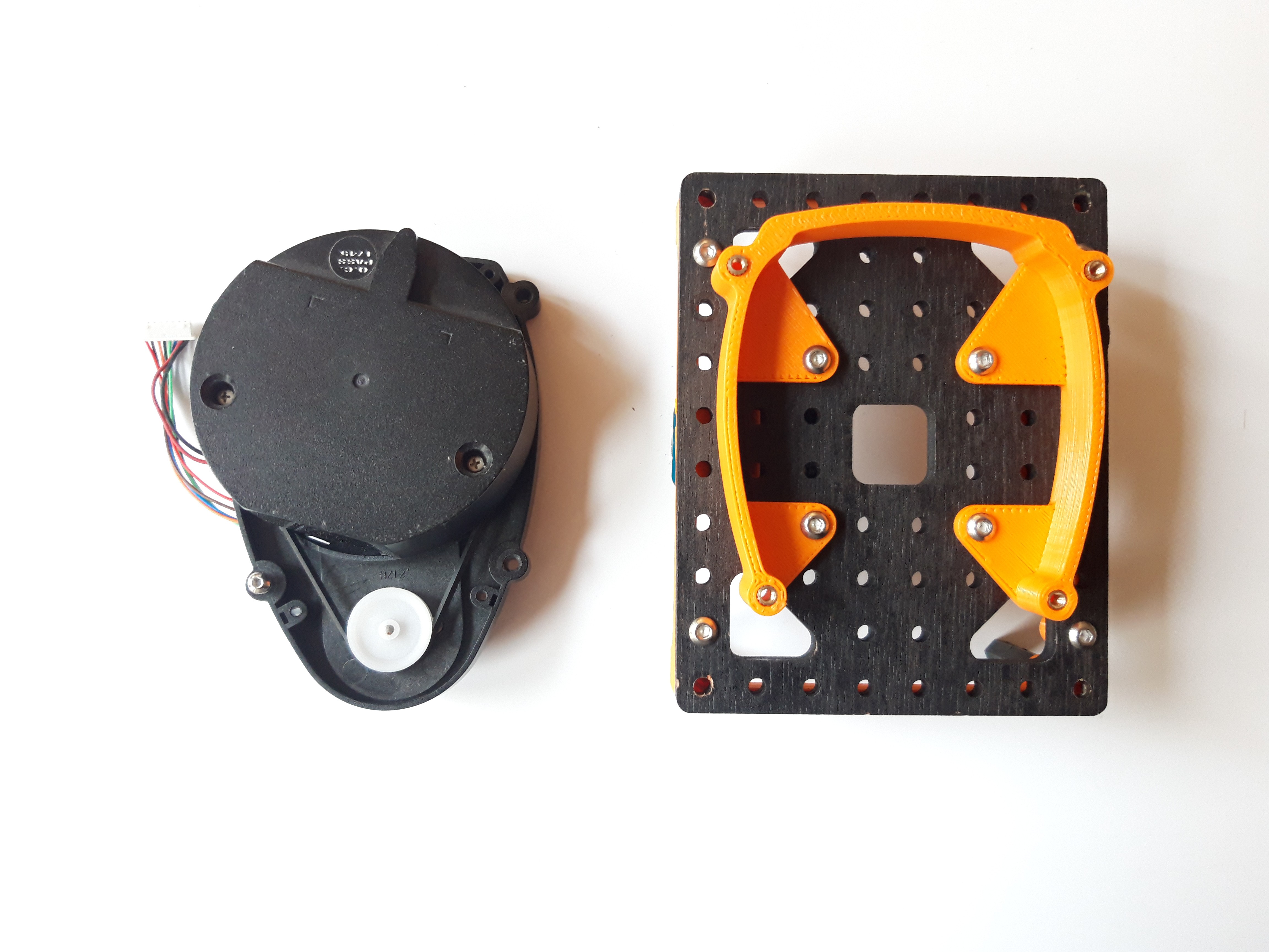
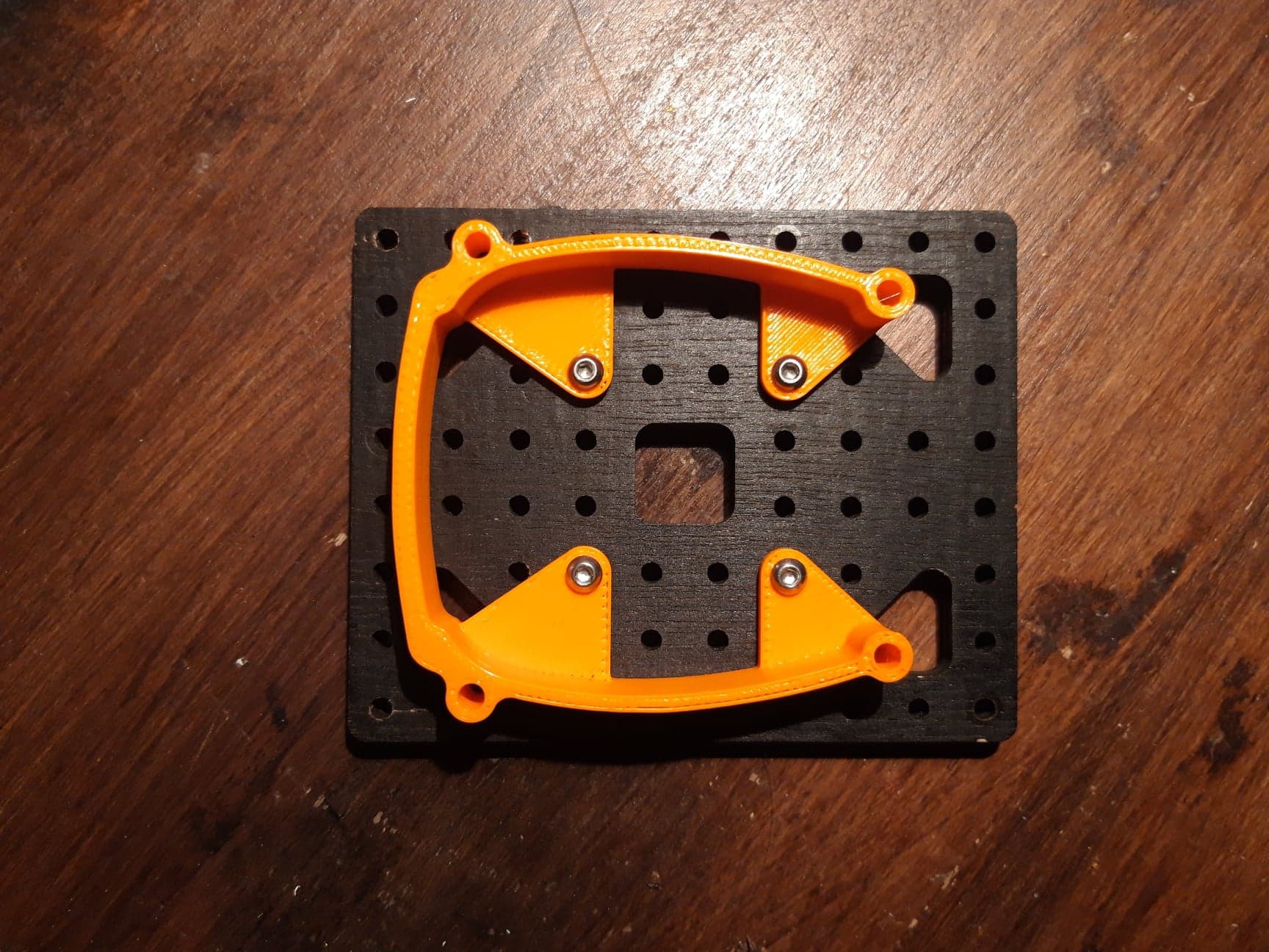
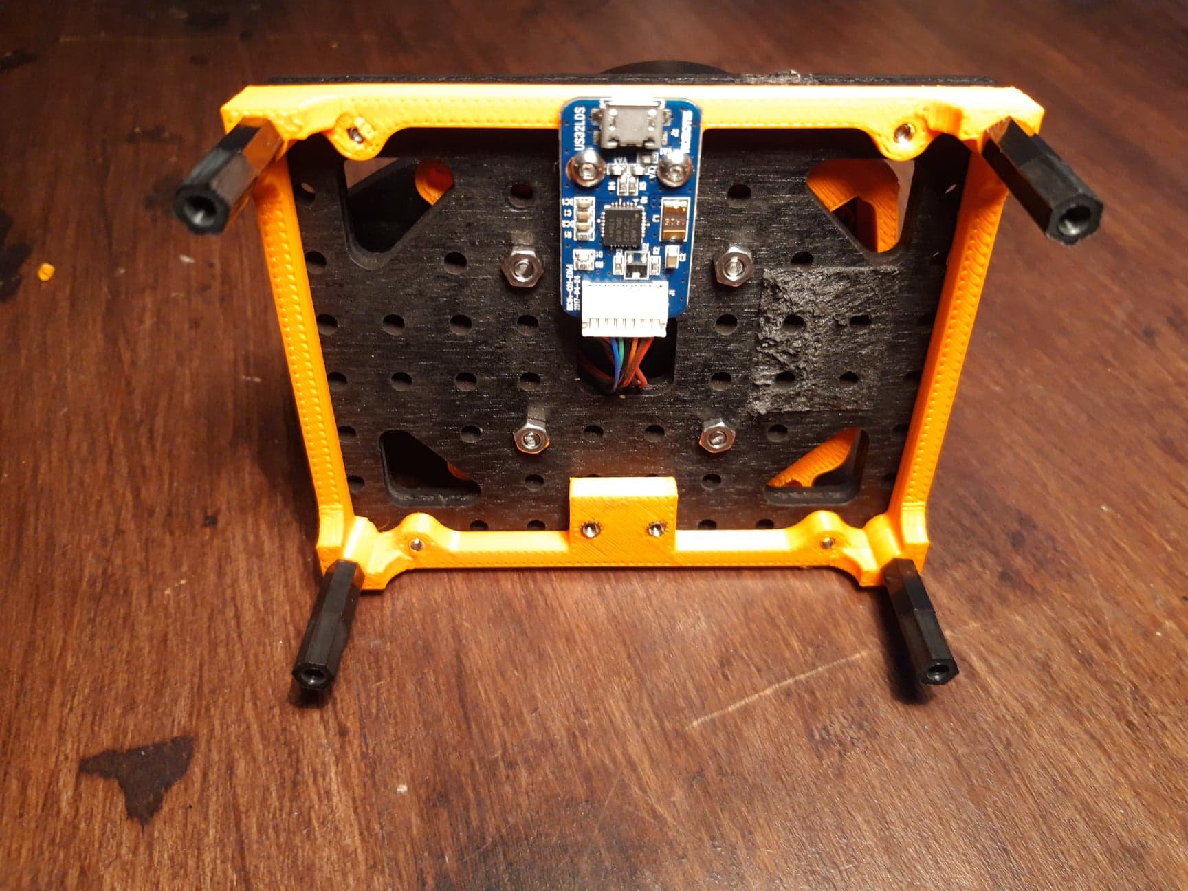
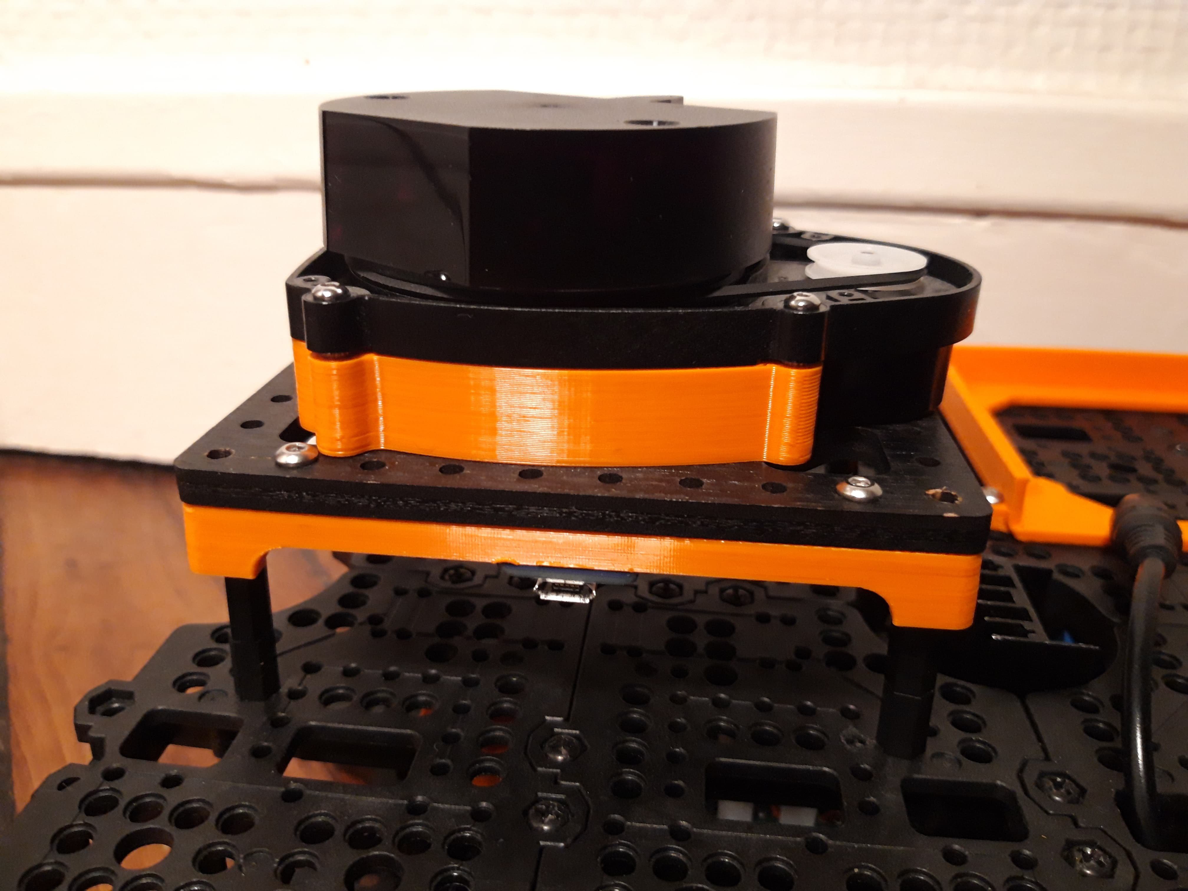
The LIDAR is the LDS01, it is the same that the original TurtleBot3. It is mounted centered on top of the upper plate with a specially designed 3D part (available in project resources). In comparison with the RPLIDAR A2, it seems to have a lower range.

Arduino CodeThe Arduino core script running on DUE is now available on github. For now it includes:
- velocity commands subscriber
- kinematic that transform velocity in body frame to wheel rate
- rate controller based on PID (described in previous log)
- odometry publisher
Some extra libraries are still needed to compile the code and will be added soon.
-
IMU processing (part 2)
11/03/2019 at 17:45 • 0 commentsIntroduction
As detailed in IMU Processing - part 1, the calibration method for accelerometers was not sufficient to guarantee a good precision. Indeed error reached up to 0.15g error on some axis, that corresponds to 8.5deg.
Spherical model calibration
The goal of the calibration is to shape a sphere from a distorted one namely the uncalibrated measures of the accelerometer when rotated around its 3 axes.
As we look to shape a sphere, we need the maths detailed in this paper: https://jekel.me/2015/Least-Squares-Sphere-Fit/. Because we are not confident with only a few measures (that correspond to the number of unknown parameters to calibrate), we need to surdetermined our system with a lot of measures using Least Square.
They are several ways to solve it:
- Singular Value Decomposition: described here that compute the pseudo inverse matrix formed by our surdetermined system that then give the unknown parameters. This method is 'lighter' enough to run on microcontroller, and gives good results
- Optimization Solver: minimize the criterion defined by the raw points to match the sphere model by varying sphere equation parameter. There are many ways to solve optimization problem, and the only ones I found that are well documented require a lot of integration to run on micro controller.
Advanced model calibration
After digging the web, I finally landed on a more advanced error model for MEMS sensors. This model also takes into account axis misalignment and axis non orthogonality, more info on the paper. Luckily the method has been implemented as well, more detail on the next paragraph.
Integration approach
Finally i decided to not perform the sensor calibration onboard, instead raw values will be processed on a computer running solvers. The obtained results will be then used by the microcontroller (Arduino Due in my case).
The calibration workflow is currently not frozen, but here are some ideas:
- get the calibration results and directly compile the code (the simplest one, and currently used)
- try to fetch a results file located on SBC at ROS node startup (unsure how it is possible from the ucontroller)
- dynamically send raw data and fetch results on demand through a ROS service for example (way more longer to implement)
As told before an excellent integration work of the selected method as been done by albertopretto on this github repo. It relies on the Ceres solver, the Google open source solver (used in SLAM cartographer). The implementation only cover gyro and accelero, I decided to use the sphere model to calibrate magnetometer and solve the least square problem with Ceres.
-
Mechanical design (part 2)
09/21/2019 at 21:41 • 0 commentsFirst Layer
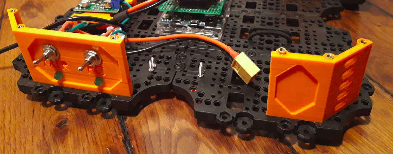
Switches holder
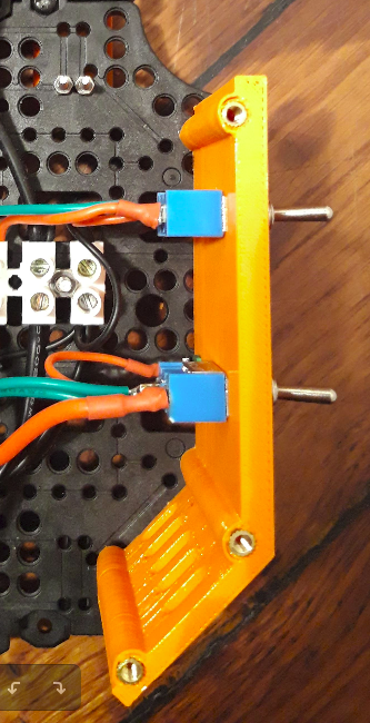
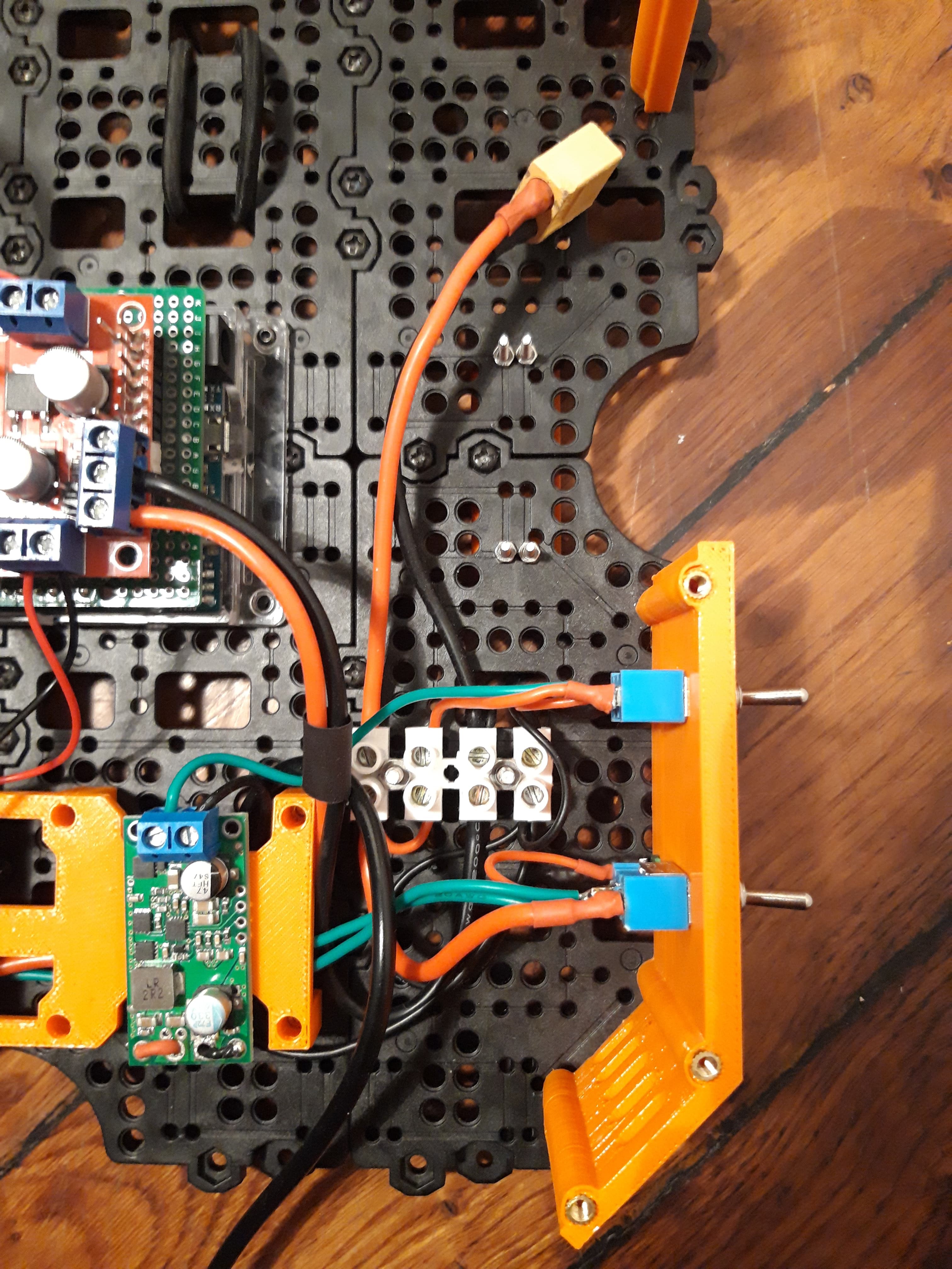
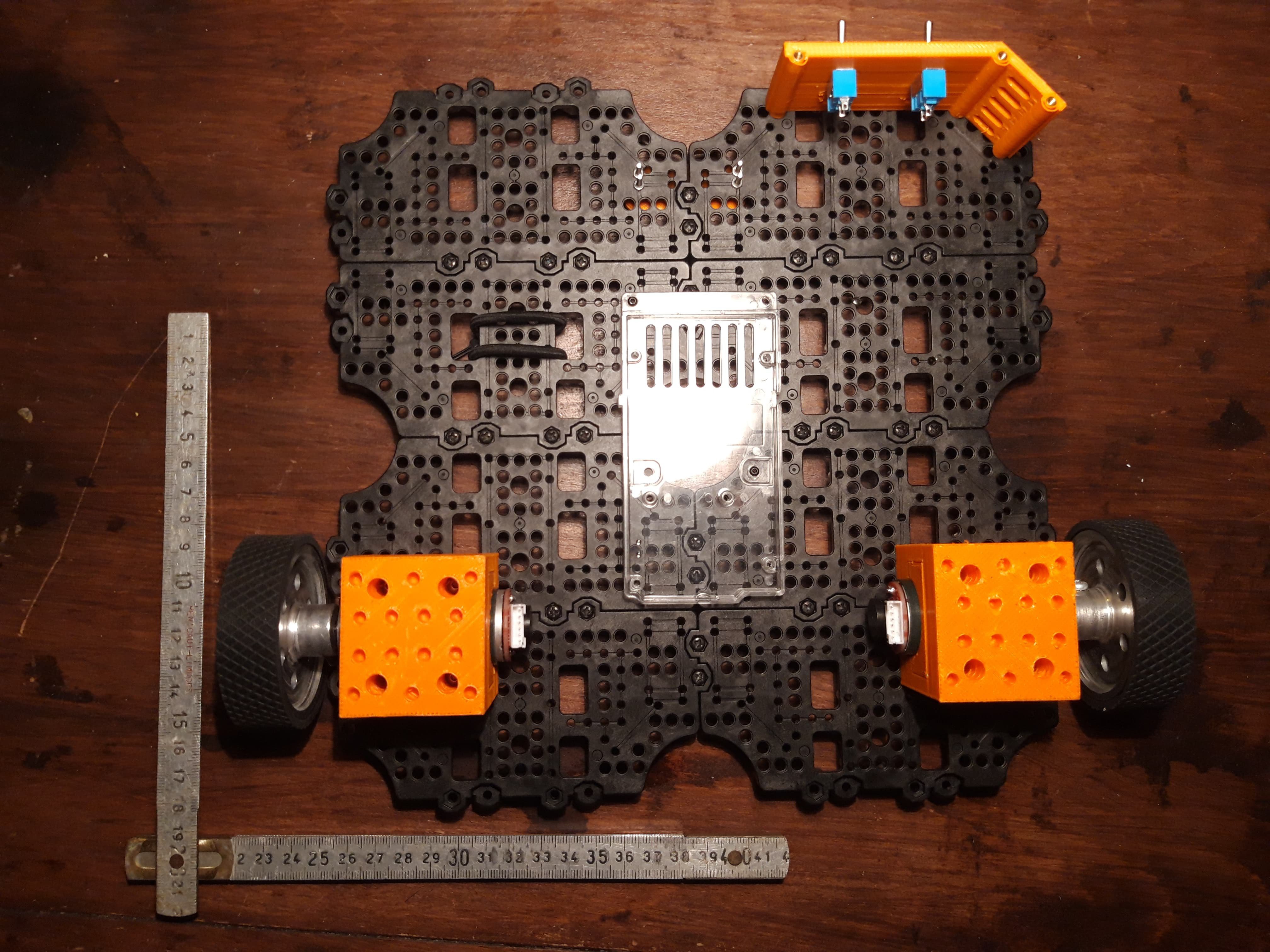
I use two switches, one to power the SBC and another one to power motor. They come with they respective LED that indicates which device is on.
The plate that hold them also serves as spacer to support the upper plate. A symmetrical plate without switches and narrower to allow battery passage completes the structure.


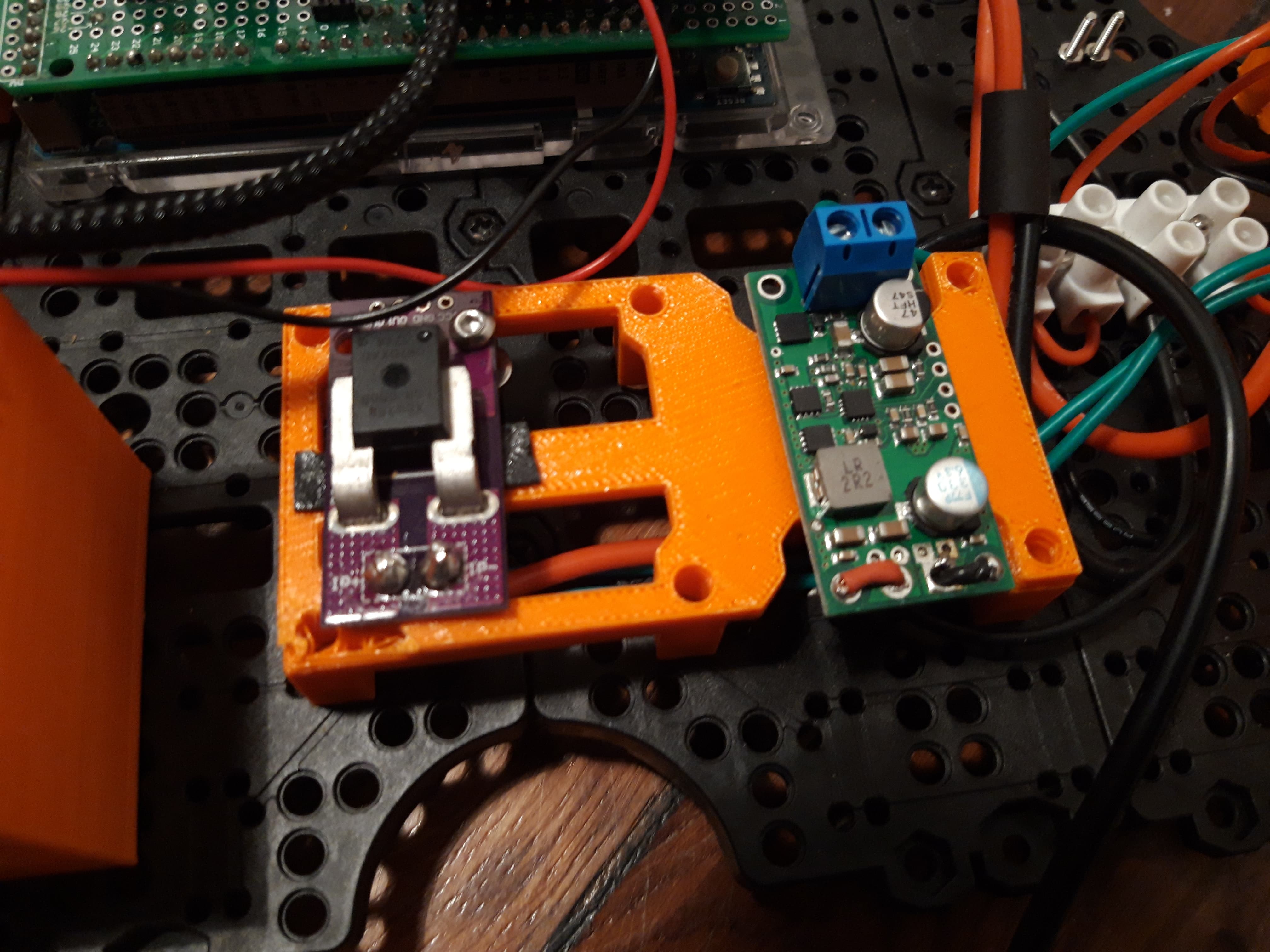
Electronic boards holder
Electronic boards are kept slightly elevated from the first layer thanks to a 3D printed 'table'. This part allows cables to pass under and reduces the 'messy aspect' near switches and battery.

Double sided tape is used to maintain boards. You can find the CJM CU 758 current sensor and the 5V pololu regulator.
Others
Basics 'bornier' are used to dispatch power.

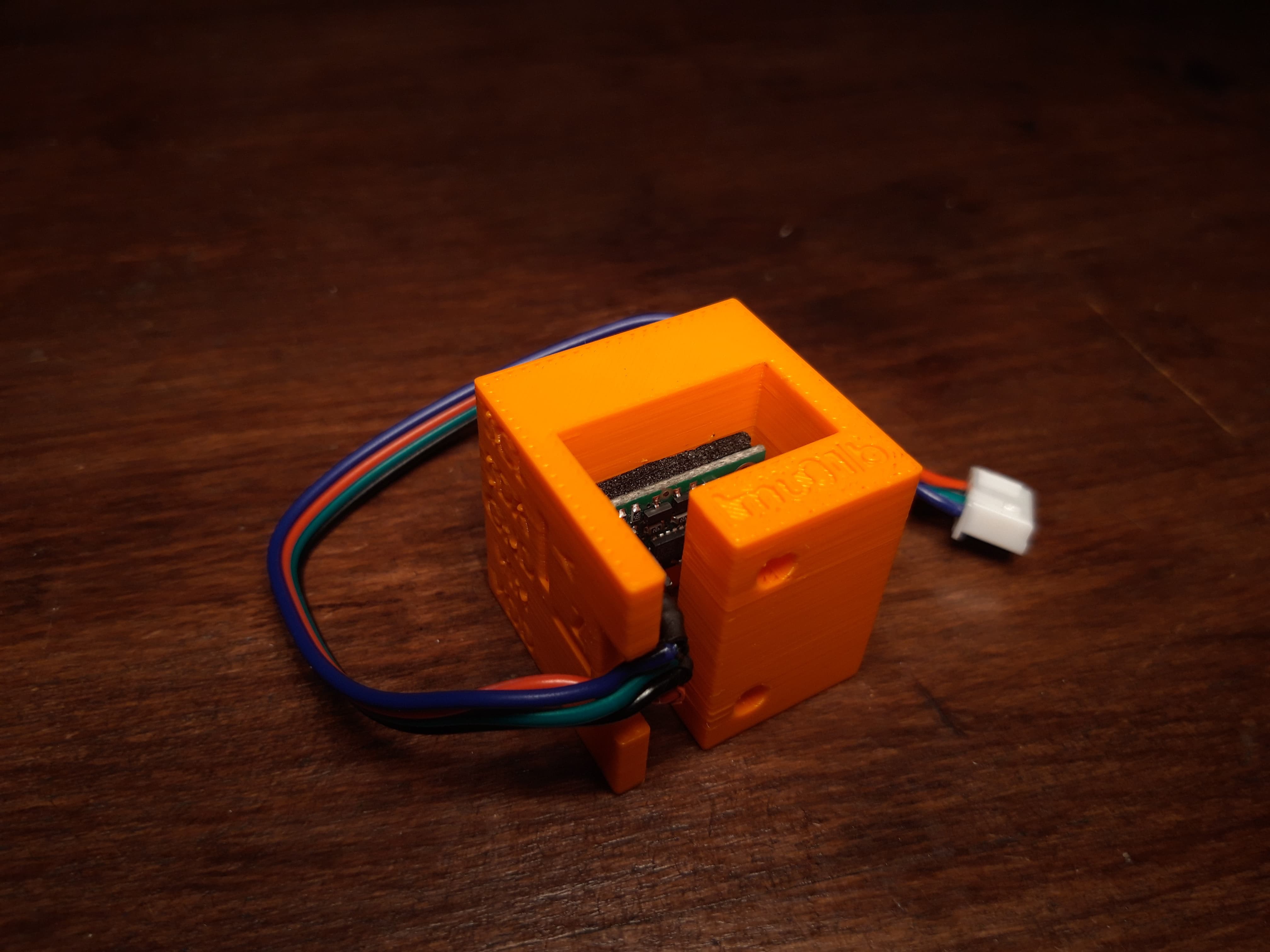
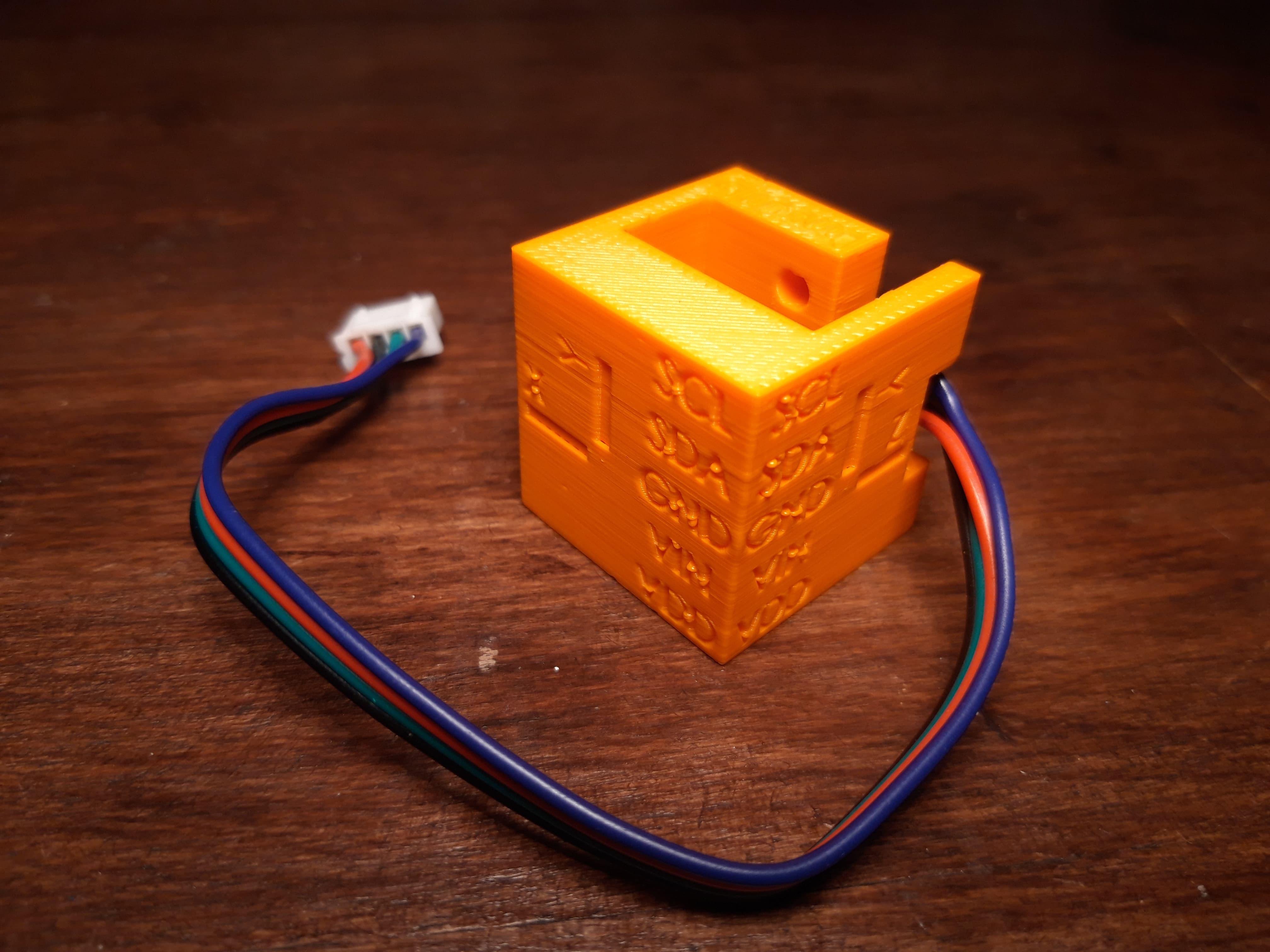
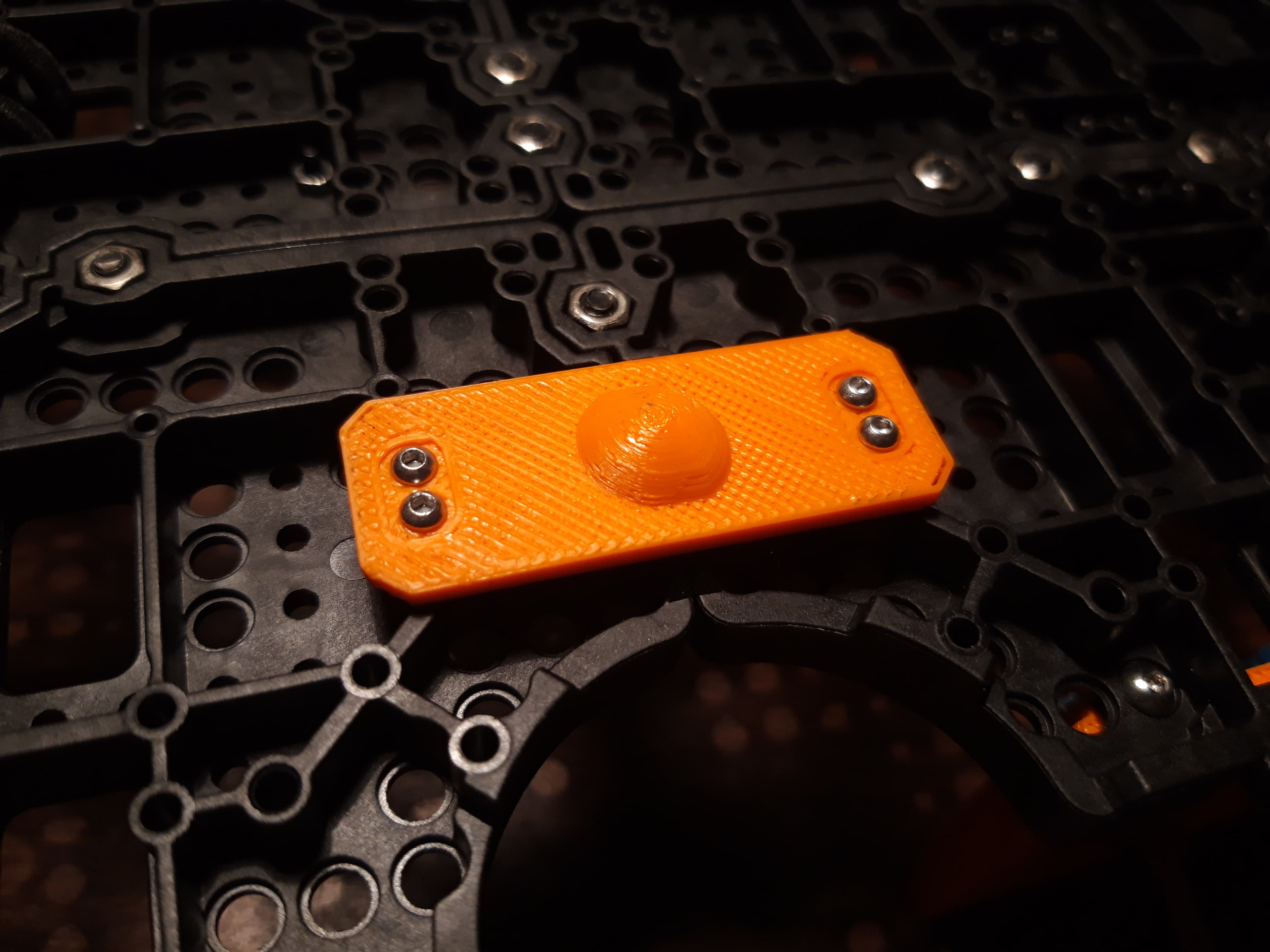
IMU holder is fixed at the current center of rotation of the platform: namely the middle of the 'motor line', it may be defined as the center of the platform in the future.

Second layer
As the project slowly drifts into building a complete robot platform which is needed to test and validate TB3 packages, I present you parts related to 'higher level' components, located on the upper plate.
Lidar mount


In order to elevate LIDAR from the upper plate, I use an intermediate wooden plate (but could be 3D printed) on which a specific part as been design to match shapes of the LDS01 LIDAR. To gain height, nylon spacers and a adaptation part are used.

-
Mechanical design (part 1)
08/27/2019 at 21:56 • 0 commentsOverall structure
Building a complete robotic frame is an interesting challenge but could be really time consuming. In order to focus on project's goals, I decided to use TurtleBot3 plates which present many advantages: numerous holes offer good modularity and molded plastic used present a higher stiffness than most 3D printer materials.

Motor holder


Motor holder are composed of two parts that tighten motor with 4 screws like a vises. Motors are soft mounted to prevent vibrations that cause noise.
IMU holder


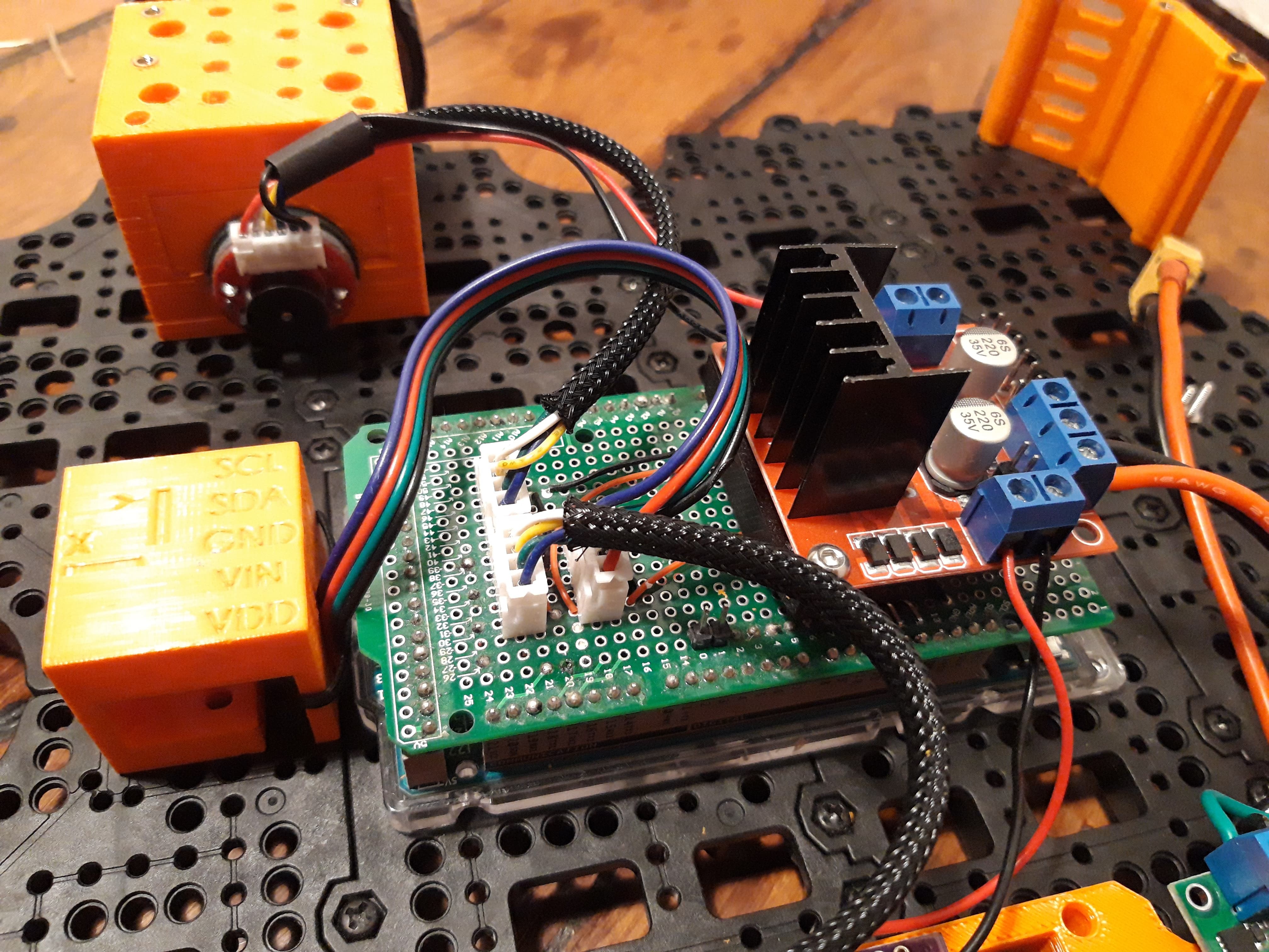
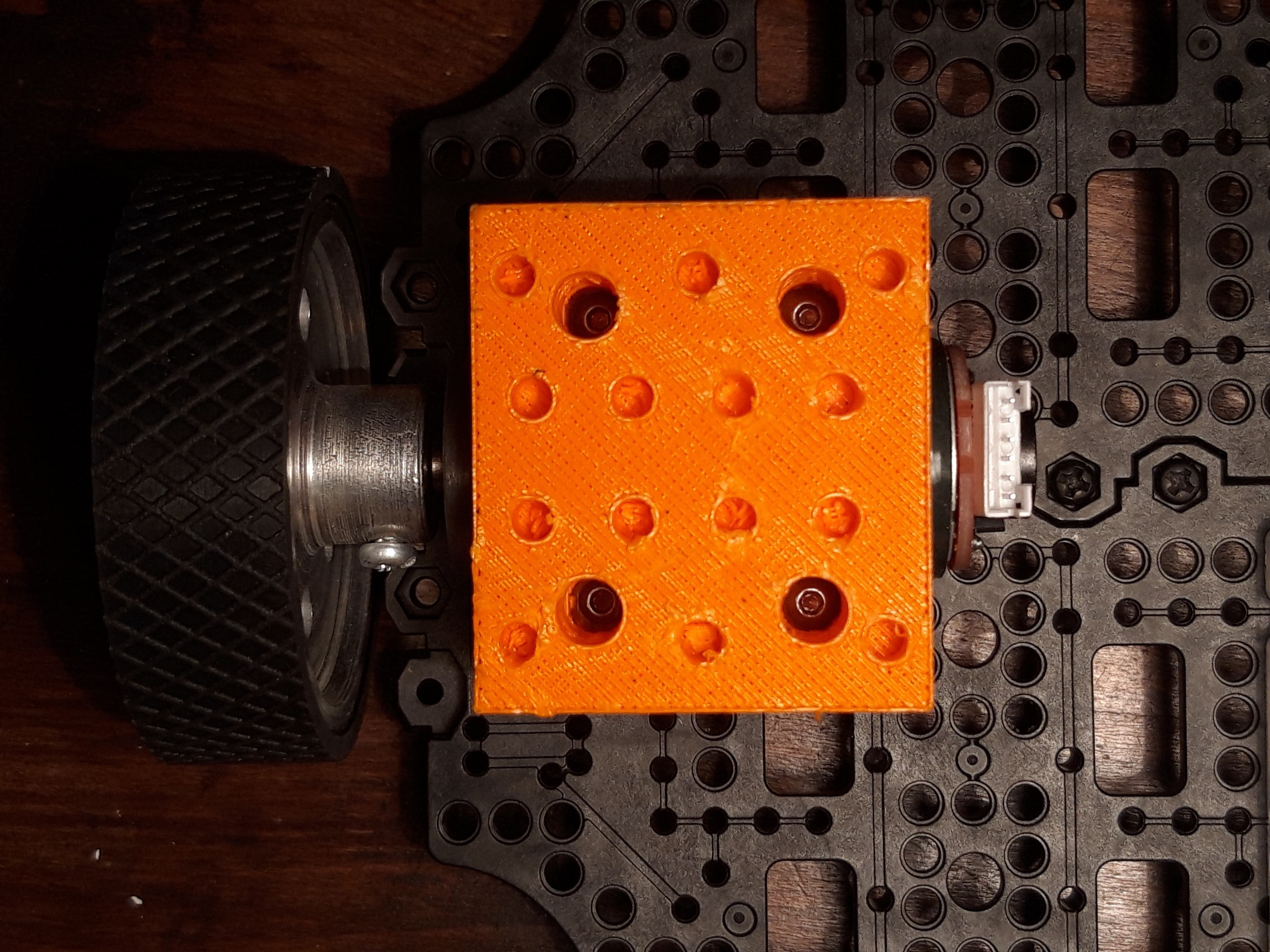
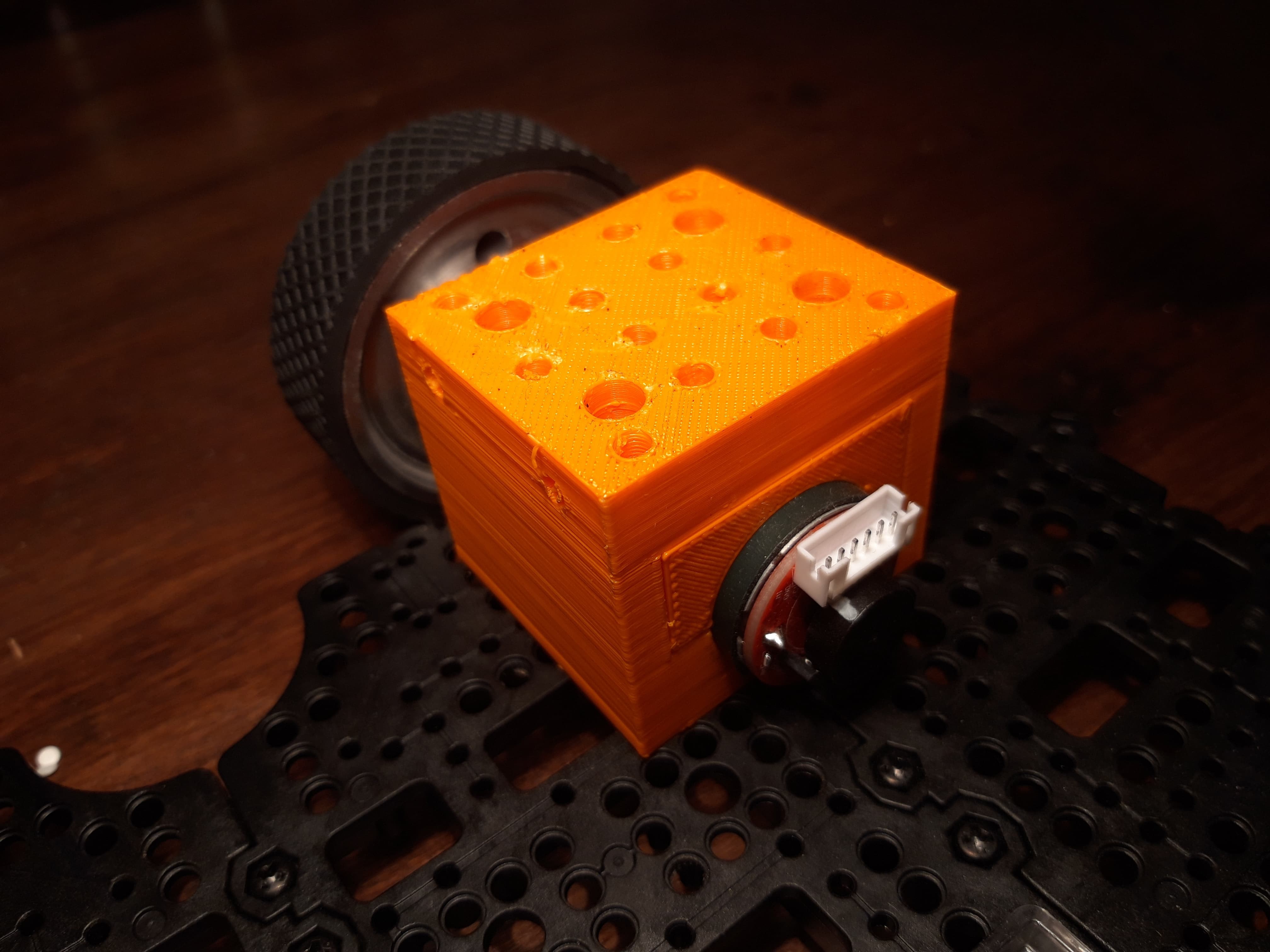
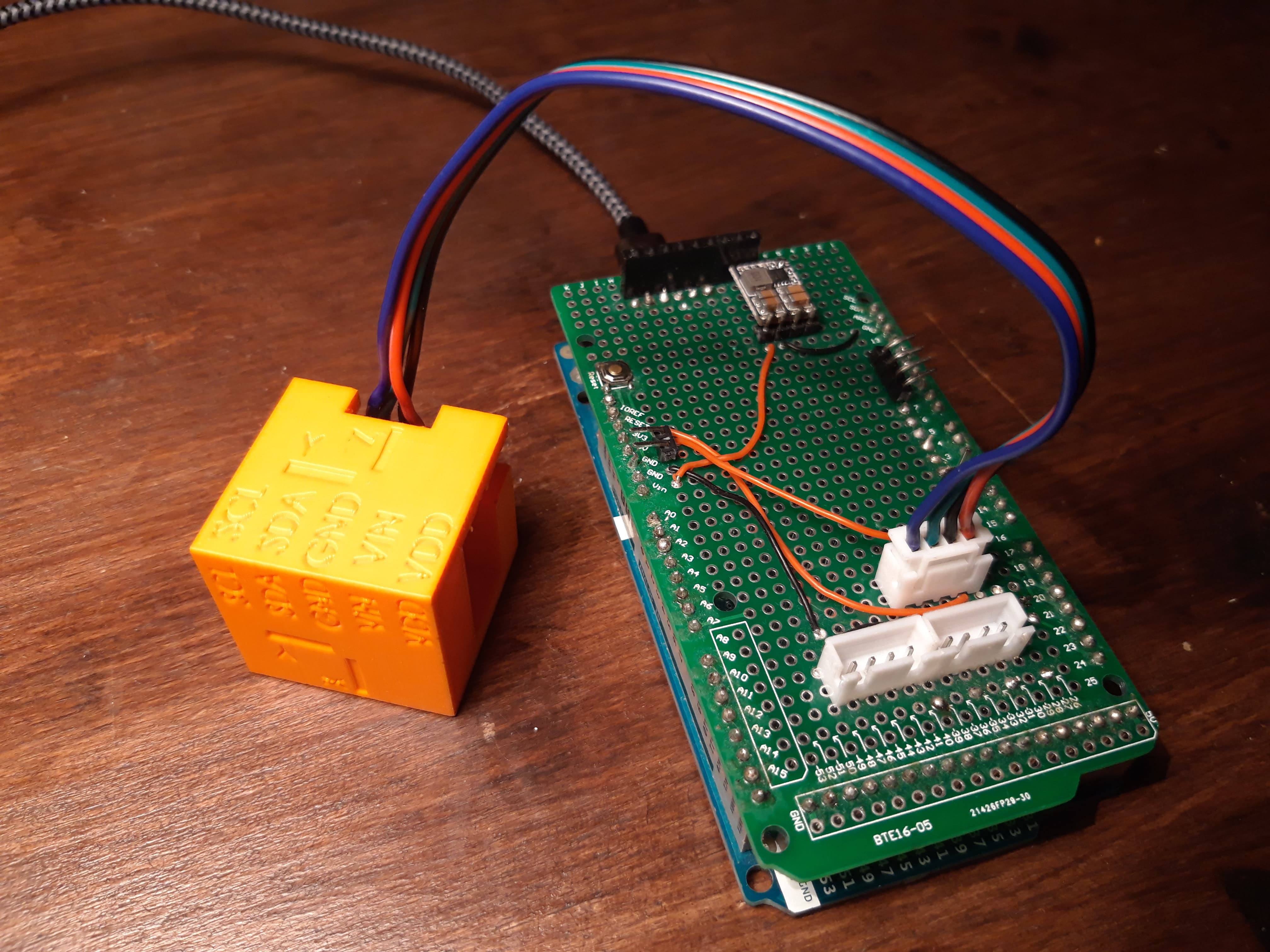
This cube will be used for algorithm tuning and calibration methods development, some holes with M2.5 inserts allow to fix it on the TB3 plates. As explain in a previous log, IMU is soft mounted with "thick tape".
Here is also an overview of the Arduino Due with its proto board.
Caster ball

Not really a ball, but should do the job.
-
IMU processing (part 1)
08/12/2019 at 17:38 • 2 commentsHardware integration
IMU used for this project is the MiniIMU-v2 from Pololu, it incorporates several chips that offers 9 degrees of freedom, allowing a complete attitude estimation.
- magnetometers, LSM303, 30Hz Output Data Rate, 1.3gauss scale
- accelerometers, LSM303, 50Hz Output Data Rate, 8g scale
- gyrometers, L3G, 190Hz Output Data Rate, 25Hz cutoff frequency, 2000°/s scale
In order to passively filter noise from mechanical structure especially from motors, the IMU should be soft mounted. It is also possible to use integrated filters provided by the chip, all information regarding available filtering frequency and settings are available in the datasheets.
Attitude algorithm
The algorithm used on the OpenCR firmware is the Madgwick complementary filter. This filter produces good results regarding advanced sensor fusion algorithms (like Kalman filters), and is able to produce complete orientation (yaw, pitch and roll), when using magnetometer (it is not the case on the current OpenCR firmware).
I also use this algorithm for this projects with some improvements:
- include magnetometer measurements
- allow varying time processing
- compute on-line gyrometers biases
- sensors calibration
Sensors calibration
Gyrometer:
An automatic bias computing is performed at firmware startup, no immobility check are done doing this process, so robot should absolutely be kept static during this period!
Biases evolve in regard of temperature and mechanical stress on the board, although their computing during robot operation is not mandatory.
Accelerometer:
Madgwick filter uses accelerometer to compute gyroscopes biases. In details, each time acceleration norm equals to gravity (the robot's speed regarding terrestrial reference frame is constant), so if accelerometer have biases this condition never appends and gyroscope estimated rates diverge from real rates.
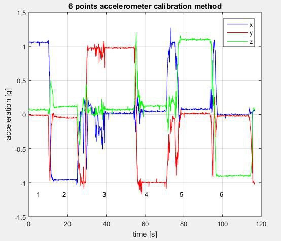
The selected method is the 6-point tumble sensor calibration, which use a quite simple sensor model, with scale factor, cross-coupling and offsets. All details can be found on this document from STMicroelectronics.
This calibration must be done after fixing the IMU on its support, because fixing it causes mechanical stress on the PCB which must be calibrated. Its not mandatory to realize systematically this calibration at startup, calibration data could be stored in memory.
Magnetometer:
The selected method consists in measuring scale factors and offsets which correspond to hard iron distortions. More details and code are available at this really well made github page from kriswiner.
This calibration must be done after fixing the IMU on its support and after inserting it inside the robot frame because all magnetic components such as metallic frame or other electronics components could modify the sensor behavior (hard iron). As for magnetometers, this calibration could be done not systematically.
Development and results
Magnetometer calibration could be easily implemented as explained in kriswiner's document.
The rotation process requires to rotate IMU around its three axis, for now result is given through the arduino console and needs further development to be integrated with ROS (it might already exist package to calibrate IMU that could be used).
After realizing several calibrations on the same magneto, converging results tend to indicated that process is OK.
Accelerometer calibration using 6 points calibrations method doesn't offer such good results.
First the method requires least square regression to obtain calibration matrix coefficients, altough this problem may have been already tackle with embedded software constrains, it still represent significant development effort.
Second, this algo relies on the strong assumption that each measured point correspond to an axis oriented strictly colinear to gravity (ie equal to -g or g). Altgough a speficic cubic part has been designed, the mechanical tolerance can't guarantee that assumption.
-
Motor speed control
08/11/2019 at 19:54 • 0 commentsWheel speed estimation
Each hall encoder produces nb_{rising edges} logical rising edges per motor rotation (due to multiple magnetization points on encoder ring).
Speed estimation relies on counting the number of logical rising edges nb_{encoder ticks} during an known time interval dt for a single sensor.
Wheel speed is then estimate with the following relation
At low speed, the signal is noisy and filtering is applied. The filter consists in a running average with higher weight on the last value. Some tuning on filter size and weights might be needed.
Wheel direction estimation
In order to estimate direction, during each rising edges of sensor A, the logical state of sensor B is read. Then a logical state is associated with a direction.
This method is quite robust but sometimes presents glitches which are removed using a median filter.
Control strategy
Linear and angular reference velocity in the robot frame are converted into left and right wheel reference speed using differential drive kinematics model.
http://www.cs.columbia.edu/~allen/F17/NOTES/icckinematics.pdf
Then a PID controller tends to make estimate speed converge to reference speed for each motor. PID's output is not directly PWM value but PWM rate.

Controller tuning
Tuning controllers could be painful and require basic understanding on effects of each Proportional, Integral and Derivative terms. To accurately tune your controller you will need to log several debug variables while playing a step reference input.
The ROS package called plotjuggler offers a complete UI for real-time visualization and logging of topics values. Simply publish debug topics with interesting values.
- Set I=0 and D=0, progressively increase P until motor get a response with a "important" overshoot (more than 50% of a step respons. Debug variables: reference speed, estimated speed, PWM rate, PWM value
- Motor response time could be long, to reduce this increase progressively D value. Be aware that this term tends to amplify noise. Debug variables: reference speed, estimated speed, PWM rate, PWM value, PWM rate from Derivative term
- At this point, PWM value might vary a lot, try to smooth it by adding Integral term
Results
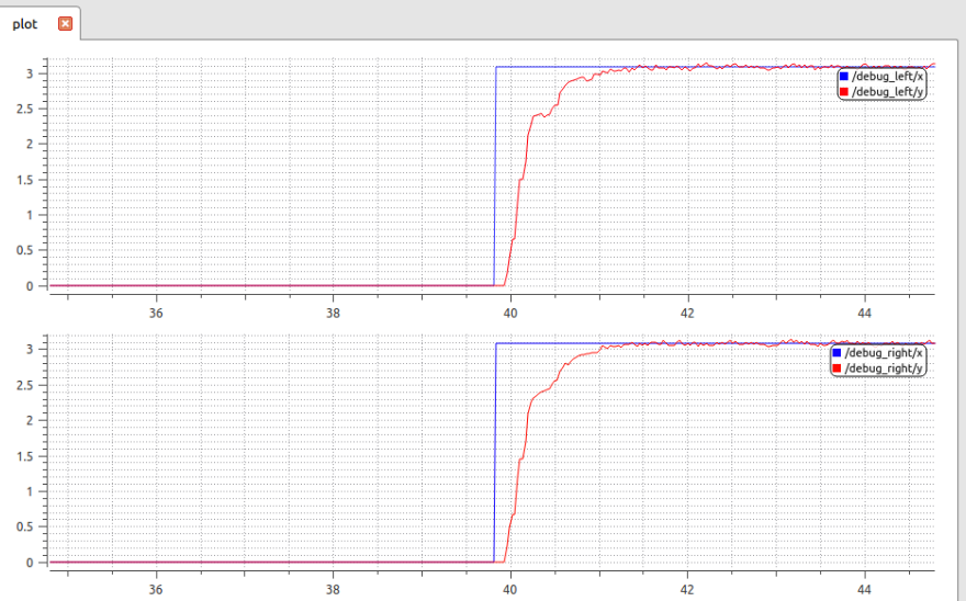
Plotting reference angular rate in blue and estimated angular rate for both motors give the following performances:
- settling time 95% = 350ms
- static error = 0

Control and estimation loop frequency
This section presents some 'business rules' that will help you to tune your controller loop and filters.
The controller frequency should be at least twice higher than your robot dynamics bandwidth (less than 5Hz for turtlebot-like robot), so running that loop at 50Hz should be able to produce a good stability and rapidity control.
The speed wheel estimation frequency should not exceed twice the minimal desired speed. From the equation given at Wheel speed estimation, it is possible to calculate the corresponding frequency.
About filter: note that delay is your worst enemy, it reduces rapidity and stability. So the more you filter raw encoders value, the more you add delay into control.
-
Hardware selection
08/11/2019 at 16:45 • 0 commentsSpecification
- expected linear speed for a 40mm wheeled robot -> [10mm/s; 1m/s]
- transformed into wheel rotational speed -> [XXRPM; XXRPM]
To match spec, we need to paid attention motor's type. For our application, three type of motor would have been OK to replace Dynamixel servo: stepper motor, brushless motor or DC geared motor. Similarly, several angular position sensors would have fit our needs:
- Quadrature Hall Sensors, they produce analog signal proportional to magnetic field
- 1 or more Logical Hall Sensors (at least 2 are needed to estimate direction). They produce a logical high state when sensors reach magnetic threshold corresponding to a locally magnetized area on the ring
- Magnetic encoders
- Optical encoders
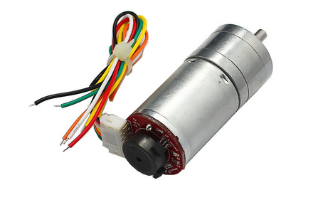
In order to keep costs as low as possible, widely available DC geared motors with 2 logical hall sensors are used for this project.

Motor and Encoder sizing
Characteristics
- max speed: RPM
- voltage: 6V
- torque: largely enough
- reduction gear: 1:850
NB: the reduction factor must be quite important, because angular position resolution depends on this value, enabling low rate control.
Motor piloting board
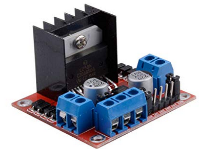
To power motors the popular double H-bridge L298N board is selected. Documentation an tutorial for this board are widely available on the web.

This board only support up to 2A per channel while our motors could demand up to XXA. In order to use safely this board, current needs to be monitored.
Current sensing
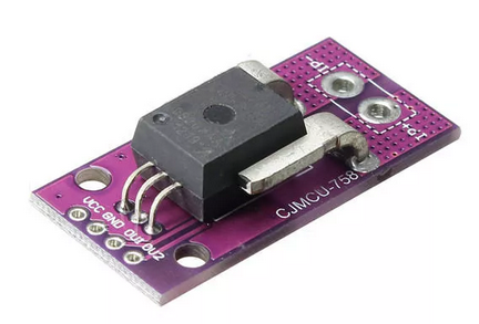
As detailed above, sensors will be used to monitor current and prevent overcharge on L298N. I choose the CJMCU-758 with ACS758LCB-050B-PFF-T that allows bidirectional current measurements.

Build your own TurtleBot 3 backbone
Implement the fantastic robotic packages offered by the TurtleBot3 robot on a budget without sacrificing features and performances.
 matop
matop