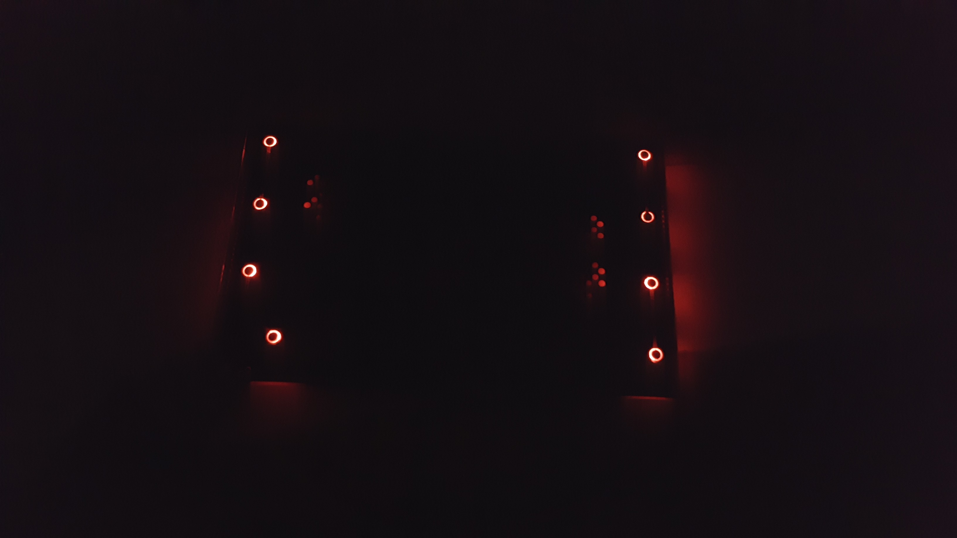
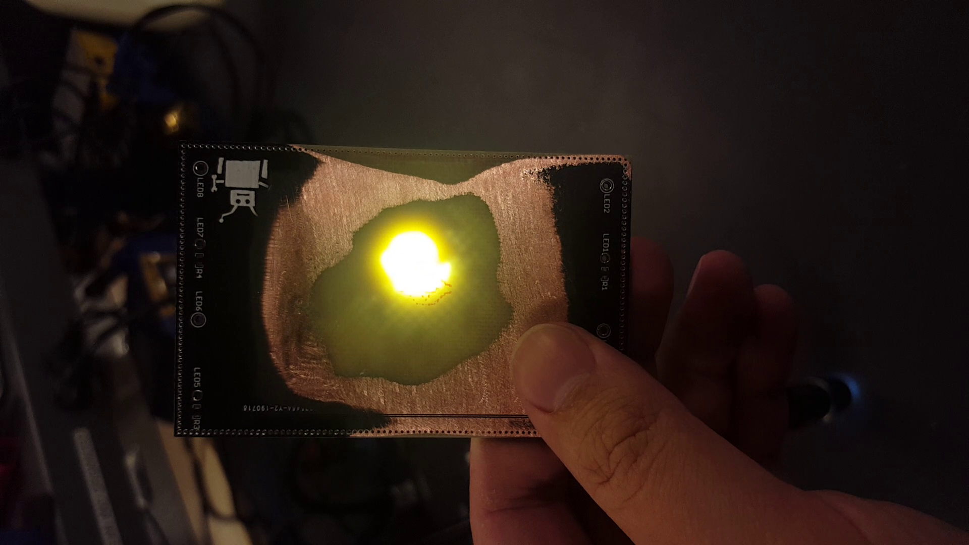
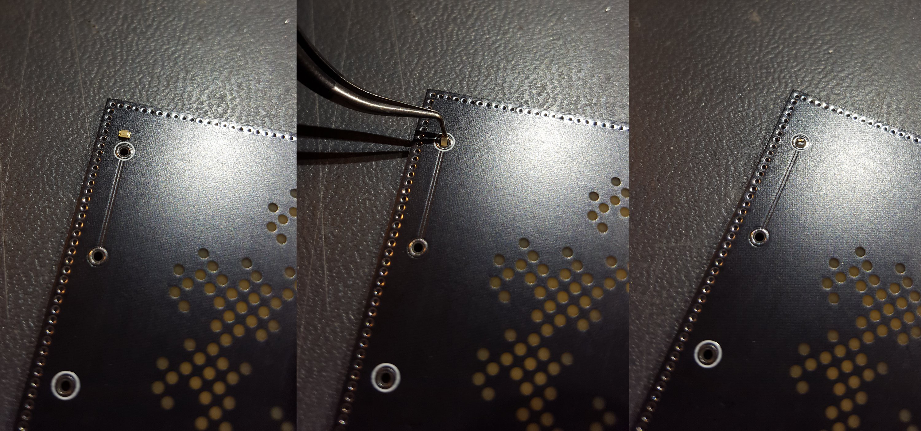
The basic concept is to insert LEDs vertically through non-plated holes. Solder will connect the component leads to exposed copper annulars on the front and back side of the board and retain the component inside the hole. 0603 parts are just slightly shorter than a standard 1.6mm PCB and a 0.8mm tall LED fits snugly into a 1.1mm hole. LEDs are positioned facing inward.
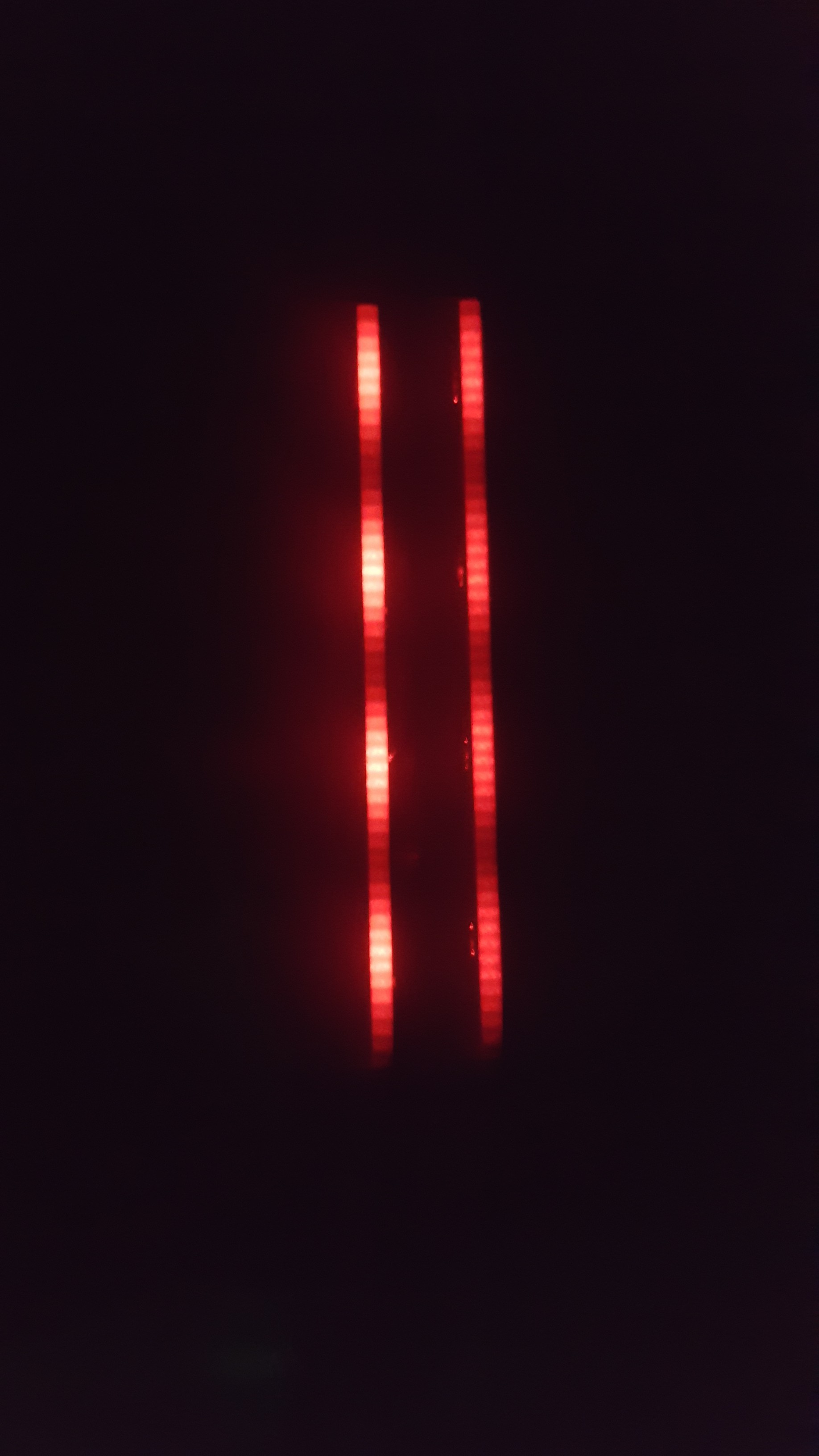
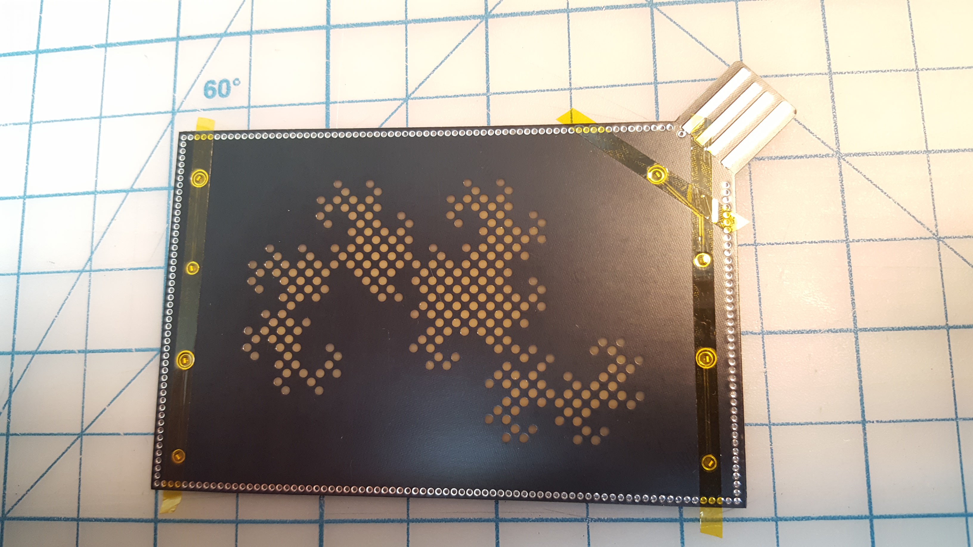
Light is confined within the FR-4 substrate with copper pours and a via fence around the outer edge of the board. The reflective underside of the copper will redirect light toward the center of the PCB. Holes in the front copper pour and soldermask allow light to exit the board.
Power is supplied to the board using a PCB USB-A plug. Two layers of electrical tape are applied to the underside of the plug to bring the 1.6mm PCB to a standard USB plug thickness of 2.2mm.
 Jeremy Ruhland



Ignore my comment, I didn't see the link to the design files on the left.