| Module | State | Notes |
| WiFi | 👍🏼 | |
| Display | 👍🏼👎🏼 | |
| Attiny Display brightness controller | 👍🏼 | |
| Keyboard over I2C | 👍🏼👎🏼 | |
| Power | 👍🏼👎🏼 |
Portable Raspberry PI Zero
a 3D printed portable computer with a QWERTY keyboard
a 3D printed portable computer with a QWERTY keyboard
To make the experience fit your profile, pick a username and tell us what interests you.
We found and based on your interests.
| Module | State | Notes |
| WiFi | 👍🏼 | |
| Display | 👍🏼👎🏼 | |
| Attiny Display brightness controller | 👍🏼 | |
| Keyboard over I2C | 👍🏼👎🏼 | |
| Power | 👍🏼👎🏼 |
pPI_bottom_rPI_REV1.stlStandard Tesselated Geometry - 1018.34 kB - 11/01/2016 at 07:21 |
|
|
pPI_bottom_rPI_REV1.123dx123dx - 206.27 kB - 11/01/2016 at 07:21 |
|
|
pPI_middle_PowerSupplyUnit_REV1.stlStandard Tesselated Geometry - 358.48 kB - 10/31/2016 at 19:09 |
|
|
pPI_top_display_QWERTY_REV1.stlStandard Tesselated Geometry - 163.36 kB - 10/31/2016 at 19:09 |
|
|
pPI_middle_PowerSupplyUnit_REV1.123dx123dx - 123.26 kB - 10/31/2016 at 19:09 |
|
So I thought I would just add the Attiny85 family to the boards by adding the following link to my Additional Boards Manager URLs in my Arduino 1.6.9 IDE and get away with it and use the wire library to hack a little LED PWM backlight controller together. But since that didn't work for the tone() lib on the #Nyan Board , why would it here?
https://raw.githubusercontent.com/damellis/attiny/ide-1.6.x-boards-manager/package_damellis_attiny_index.json
So I then look around and find this library on GitHub https://github.com/rambo/TinyWire and with it's help I was able to whip together the LED controller! The idea here is that the pin 3 is connected to the PI and when toggled will write the PWM to pin 4. This PWM value can be set via I2C address 0x04.
#define I2C_SLAVE_ADDRESS 0x4
#include <TinyWireS.h>

int pwm_value = 127;
#ifndef TWI_RX_BUFFER_SIZE
#define TWI_RX_BUFFER_SIZE ( 16 )
#endif

void setup() {

  TinyWireS.begin(I2C_SLAVE_ADDRESS);
  TinyWireS.onReceive(receiveEvent);

    pinMode(3, INPUT);
    pinMode(4, OUTPUT);
}

void loop() {
  TinyWireS_stop_check();
  writeLed();
}

void writeLed()
{
  if (digitalRead(3) == HIGH)
    {
      analogWrite(4, pwm_value);
    }
    else
    {
      digitalWrite(4, LOW);
    }
  }

  void receiveEvent(uint8_t howMany)
{
    if (howMany < 1)
    {
        // Sanity-check
        return;
    }
    if (howMany > TWI_RX_BUFFER_SIZE)
    {
        // Also insane number
        return;
    }

    // ignore write address
    TinyWireS.receive();
    howMany--;

    if (!howMany)
    {
        // This write was only to set the buffer for next read
        return;
    }
    while(howMany--)
    {
      pwm_value = TinyWireS.receive();
    }
}
I've mapped pin12 and pin13 to play audio! woot.
The following code is not mine and taken from:
https://www.raspberrypi.org/forums/viewtopic.php?f=44&t=39138
I just want to have everything in one place and have a copy of it somewhere.
/*
Utility to switch Raspberry-Pi GPIO pin functions
Tim Giles 01/04/2013

Usage:
$ gpio_alt -p PIN_NUMBER -f ALT_NUMBER

Based on RPi code from Dom and Gert, 15-Feb-2013,
and Gnu getopt() example
*/

#include <ctype.h>
#include <stdio.h>
#include <stdlib.h>
#include <unistd.h>
#include <fcntl.h>
#include <sys/mman.h>

#define BCM2708_PERI_BASE        0x20000000
#define GPIO_BASE                (BCM2708_PERI_BASE + 0x200000) /* GPIO controller */
#define PAGE_SIZE (4*1024)
#define BLOCK_SIZE (4*1024)

int  mem_fd;
void *gpio_map;
volatile unsigned *gpio;
void setup_io();

// GPIO setup macros. Always use INP_GPIO(x) before using OUT_GPIO(x) or SET_GPIO_ALT(x,y)
#define INP_GPIO(g) *(gpio+((g)/10)) &= ~(7<<(((g)%10)*3))
#define OUT_GPIO(g) *(gpio+((g)/10)) |=  (1<<(((g)%10)*3))
#define SET_GPIO_ALT(g,a) *(gpio+(((g)/10))) |= (((a)<=3?(a)+4:(a)==4?3:2)<<(((g)%10)*3))

#define GPIO_SET *(gpio+7)  // sets   bits which are 1 ignores bits which are 0
#define GPIO_CLR *(gpio+10) // clears bits which are 1 ignores bits which are 0


int main (int argc, char **argv) {
  int opt, flag, n_pin, n_alt;
  flag=0;

  while ((opt = getopt (argc, argv, "hp:f:")) != -1) {
    switch (opt) {
    case 'h':
      break;
    case 'p':
      n_pin = atoi(optarg); flag |= 0b0001; break;
    case 'f':
      n_alt = atoi(optarg); flag |= 0b0010; break;
    case '?':
      // getopt() prints error messages, so don't need to repeat them here
      return 1;
    default:
      abort ();
    }
  }

  if (flag != 0b0011) {
    fprintf (stderr, "Usage:\n$ gpio_alt -p PIN_NUM -f FUNC_NUM\n");
    return 1;
  }

  setup_io(); // Set up gpi pointer for direct register access
  INP_GPIO(n_pin);  // Always use INP_GPIO(x) before using SET_GPIO_ALT(x,y)
  SET_GPIO_ALT(n_pin, n_alt);

  printf("Set pin %i to alternative-function %i\n", n_pin, n_alt);

  return 0;
}


void setup_io() {
   /* open /dev/mem */
   if ((mem_fd = open("/dev/mem", O_RDWR|O_SYNC) ) < 0) {
      printf("can't open /dev/mem \n");
      exit(-1);
   }

   /* mmap GPIO */
   gpio_map = mmap(
      NULL,             //Any adddress in our space will do
      BLOCK_SIZE,       //Map length
      PROT_READ|PROT_WRITE,// Enable reading & writting to mapped memory
      MAP_SHARED,       //Shared with other processes
      mem_fd,           //File to map
      GPIO_BASE         //Offset to GPIO peripheral
   );

   close(mem_fd); //No need to keep mem_fd open after mmap

   if (gpio_map == MAP_FAILED) {
      printf("mmap error %d\n", (int)gpio_map);//errno also set!
      exit(-1);
   }

   // Always use volatile pointer!
   gpio = (volatile unsigned *)gpio_map;
}
One time setup:
gcc -o gpio_alt gpio_alt.c
sudo chown root:root gpio_alt
sudo chmod u+s gpio_alt
sudo mv gpio_alt /usr/local/bin/
Cron that:
gpio_alt -p 13 -f 0
gpio_alt -p 12 -f 0
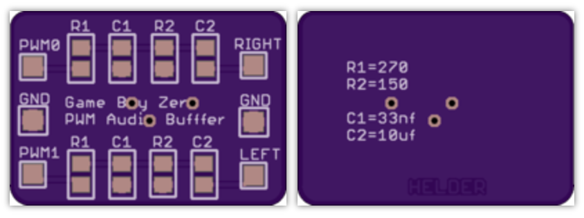
There is currently no sound on this board, but I've ordered this anyway with some testpoints for the possible sound pins and an extra board you can check out below (not designed by me but someone who builds raspberry pi portables). The attiny85 is connected to the PI via I2C and the TFT LED output of the driver - think basic on/off via driver and pwm via i2c. It's a decent prototyping board to get along, I think.
https://oshpark.com/shared_projects/qUEOjE0n
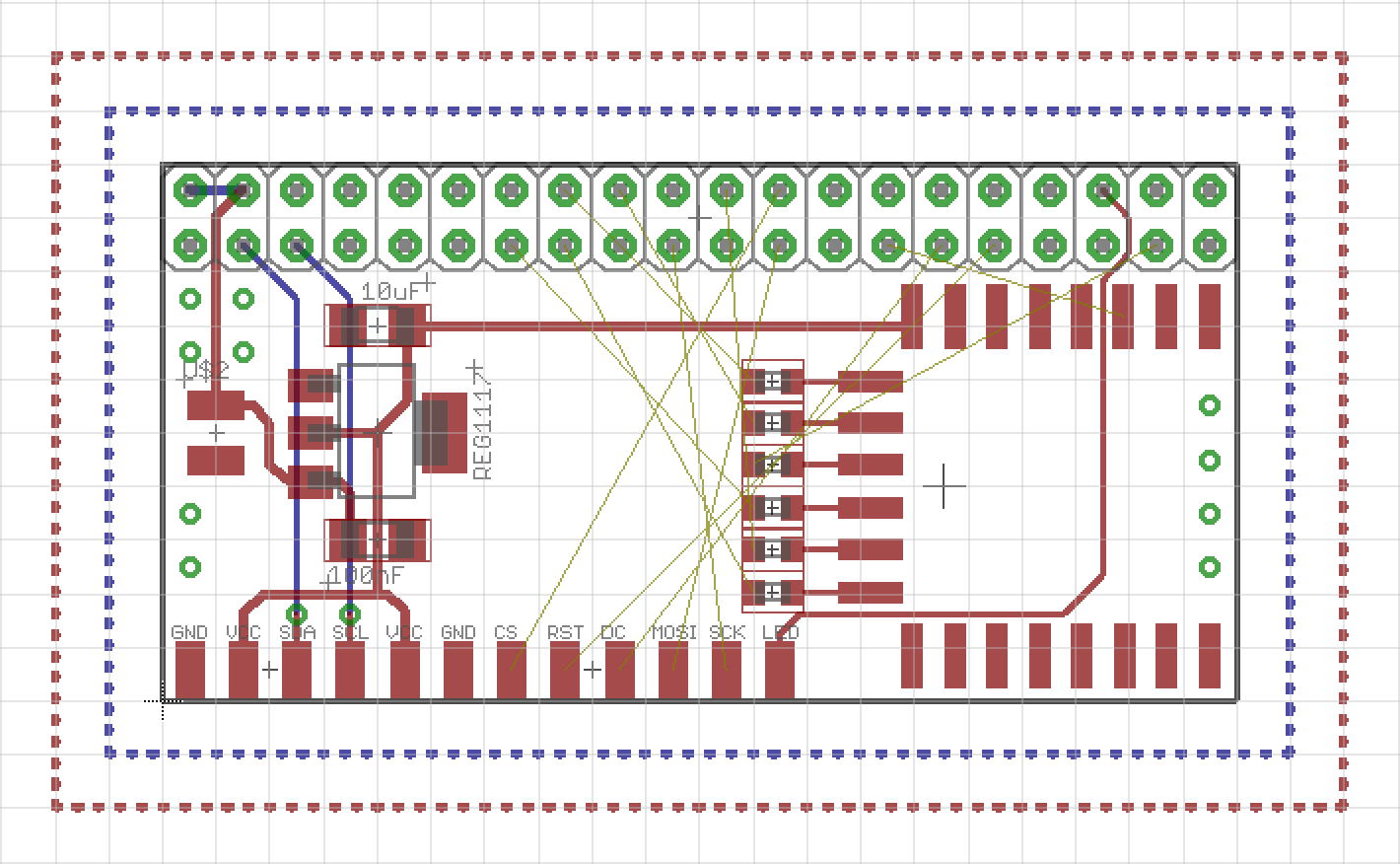
soo, still not validated, but I'm happy to give it a try as soon as possible - a breakout board to connect the Raspberry PI with the TFT display, wi-fi and I2C and stuff. I'm tired.
Yay, I won something! When I saw the blog post about the Enlightened Raspberry Pi Contest I must have over looked that I won something, because I was surprised when Adam Fabio wrote me to get my address to send me a sweet camera module! Not sure if it will end up in this project or the cluster thing, but I will find a good project for it! With all those PIs I have it shouldn't be a problem.
https://hackaday.io/contest/15532/log/49182-and-the-winners-are
https://docs.google.com/spreadsheets/d/1G__6bgoXlyRspCsvcebNKyEUlDYK1BtcHlGwnXLq2EA/edit?usp=sharing
https://hackaday.io/project/8678/instructions
http://marcosgildavid.blogspot.de/2014/02/getting-ili9341-spi-screen-working-on.html
https://learn.adafruit.com/introducing-the-raspberry-pi-zero/audio-outputs
All that Pin X is GPIO Y got me confused... so I had to "map" the pins.
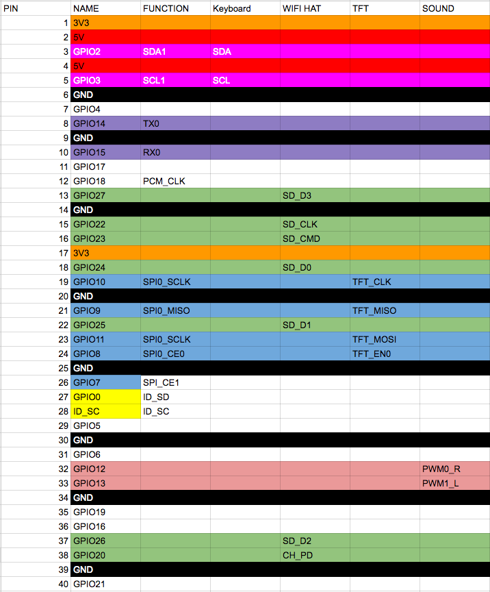
Nothing but the keyboard works yet.
Here's the closed case.
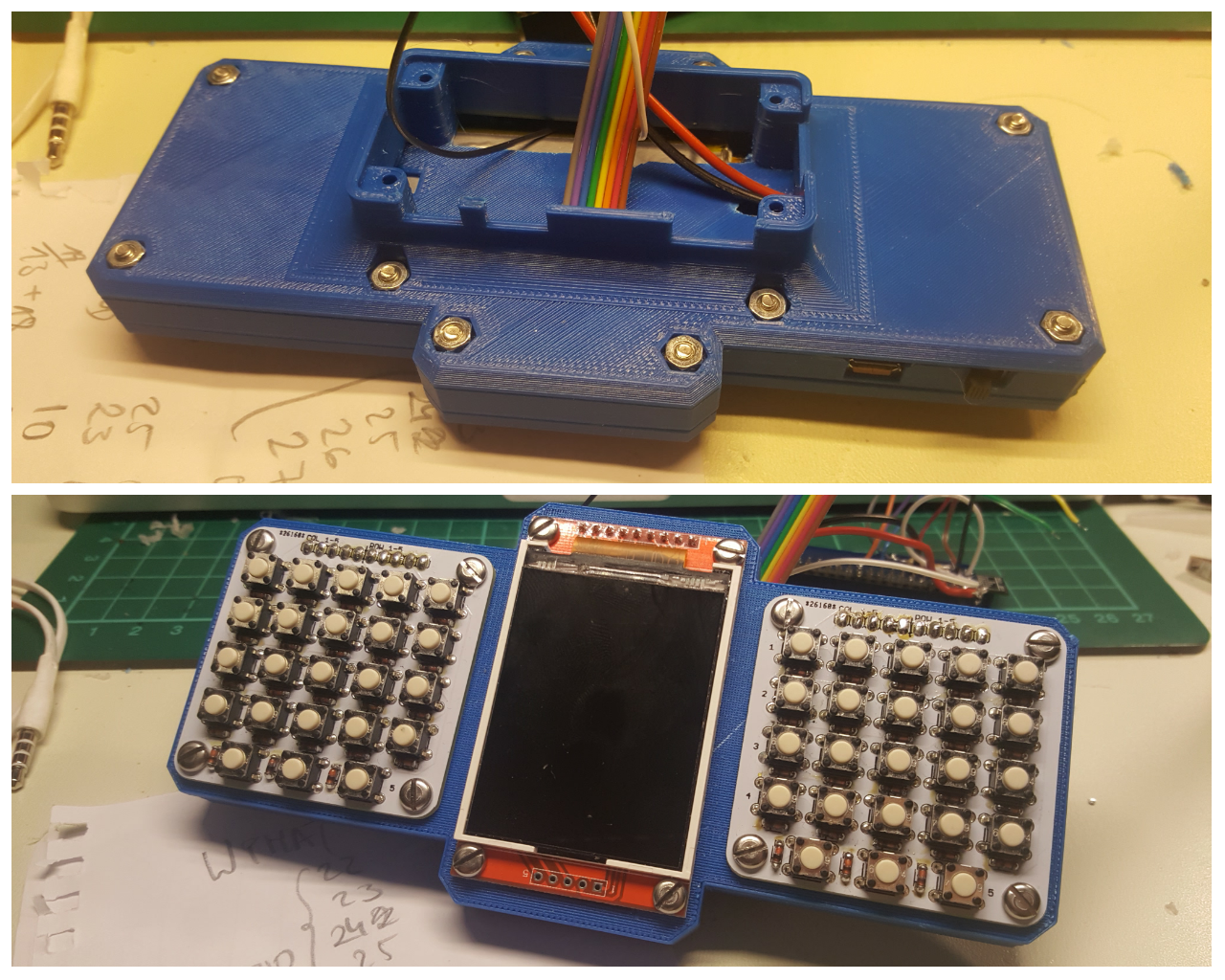
Python script is about the same where I was before. Python is weird when you're coming from JS and PHP, let me tell you.
AND the uinput part works!! woot! Thanks to adafruit, mainly. And my copy and paste skills.
I still need to map the keys and find the driver for the display (MacGyver was drawn by an adafruit python library).
import subprocess
import sys
import time

import Adafruit_GPIO as GPIO
import Adafruit_GPIO.I2C as I2C
import Adafruit_GPIO.PCF8574 as PCF

import uinput

row = 1
rowI = 1
col = 1024

addressH = 0x20
addressL = 0x21

gpioH = PCF.PCF8574(addressH, busnum=1)
gpioL = PCF.PCF8574(addressL, busnum=1)

KEY_MAPPING = {
                                0: uinput.KEY_UP,    # Each line here should define a $
                                1: uinput.KEY_DOWN,  # that maps the capacitive touch $
                                2: uinput.KEY_LEFT,  # to an appropriate key press.
                                3: uinput.KEY_RIGHT, #
                                4: uinput.KEY_B,     # For reference the list of possi$
                                5: uinput.KEY_A,     # values you can specify is defin$
                                6: uinput.KEY_ENTER, # http://www.cs.fsu.edu/~baker/de$
                                7: uinput.KEY_SPACE, # http/source/linux/include/linux$
                          }


# Make sure uinput kernel module is loaded.
subprocess.check_call(['modprobe', 'uinput'])

# Configure virtual keyboard.
device = uinput.Device(KEY_MAPPING.values())

def shiftRange (start, end):
        while start > end:
                yield start
                start = start>>1

while True:
        rowS = 0x03FF ^ row
        rowL = (rowS<<5) & 0x00FF
        rowH = (rowS>>3) & 0x00FF

        addL = rowL | 0x1F
        addH = rowH

        gpioH.iodir = addH
        gpioL.iodir = addL

        gpioH._write_pins()
        gpioL._write_pins()

        keys = gpioL._read_pins()

        keys = keys & 0x1F;
        keysI = 1
        for k in shiftRange(16,0):
                if k & keys == 0:
                        device.emit_click(KEY_MAPPING[rowI-1])
                        time.sleep(0.5)
                keysI += 1

        rowI += 1
        row = row << 1
        if row == col:
                row = 1
                rowI = 1
That's my current state for the actual keyboard. I will probably drop this and move over to python, since I just don't get the uinput stuff in C and the linux input system. Hey future Dave, research before developing, you know this stuff!
https://github.com/adafruit/Adafruit_Python_MPR121
#include <wiringPi.h>
#include <wiringPiI2C.h>
#include <stdio.h>

int fdH;
int fdL;
int fd;
int rpl;

int ret;

int row = 1;
int rowI = 1;
int col = 1024;

int i = 0;
int j = 0;
int k = 0;

void printByte(int a)
{
        printf("\n0x");
        for (j=0x8000; j>0; j=j>>1)
        {
                if ((a&j) > 0) printf("1");
                else printf("0");
        }
}


int main (void)
{
        wiringPiSetup ();
        fdH = wiringPiI2CSetup(0x20); // rows only
        fdL = wiringPiI2CSetup(0x21); // cols with rows

        for (;;)
        {
                int rowS = 0x03FF ^ row;
                int rowL = (rowS<<5) & 0x00FF; // High
                int rowH = (rowS>>3) & 0x00FF; // Low
                int addL = rowL | 0x1F;
                int addH = rowH;

                wiringPiI2CWrite(fdH, addH);
                wiringPiI2CWrite(fdL, addL);

                int keys = wiringPiI2CRead(fdL);
                keys = keys & 0x1F;
                int keyI = 1;
                for (k=0x10; k>0; k=k>>1)
                {
                        if (!(k & keys))
                        {
                                delay(50);
                                printf("%i\t%i\n", keyI, rowI);
                        }
                        keyI++;
                }

                rowI++;
                row = row << 1;
                if (row == col)
                {
                        row = 1;
                        rowI = 1;
                }
        }
        return 0 ;
}
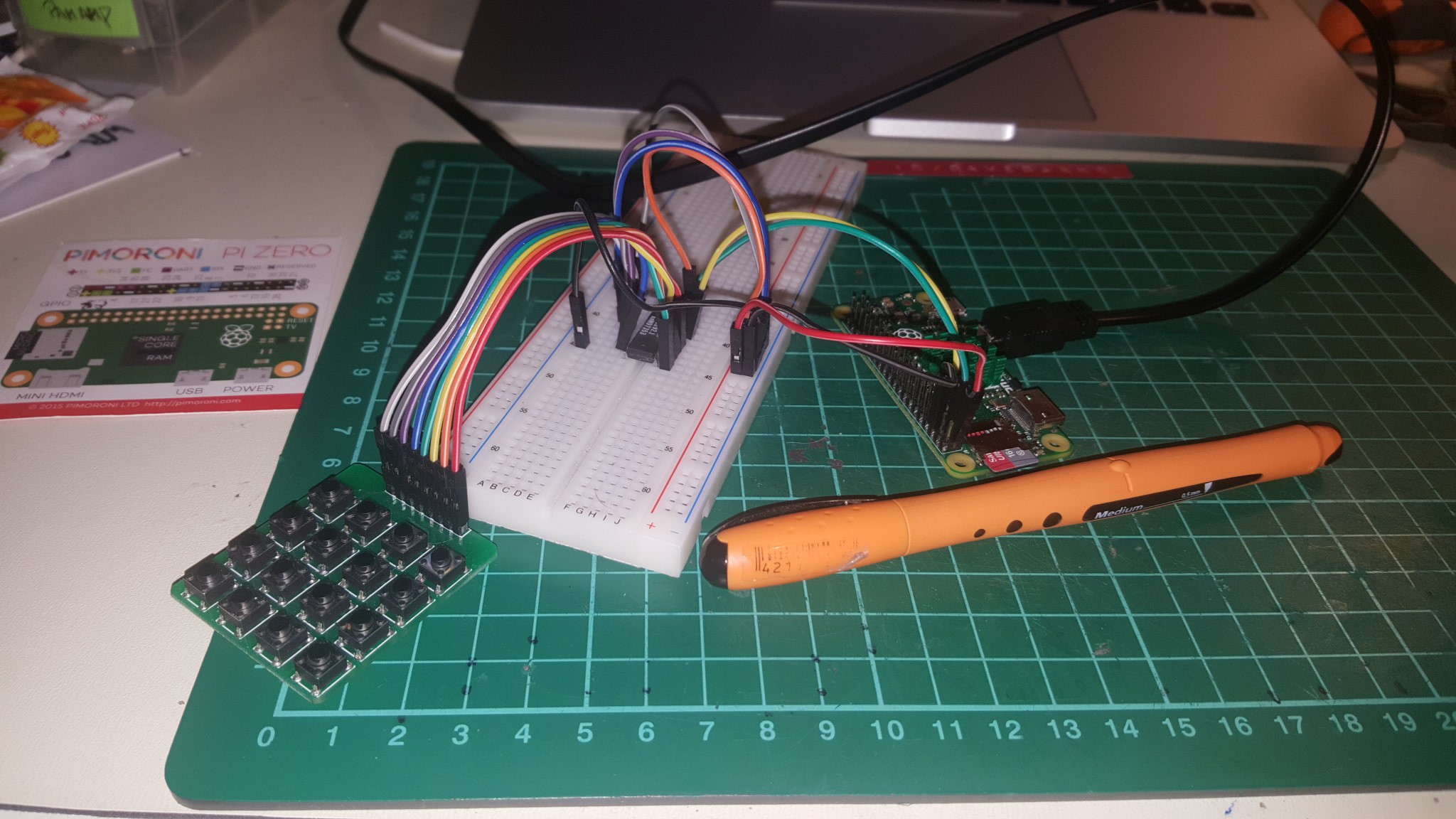
It took me a while to get this far and I'm even further away from being done. I couldn't find a good example how to use the I2C library for it. http://wiringpi.com/reference/i2c-library/
As I understand now, the function wiringPiI2CSetup gives you a file handle (everything in linux is a file, right?) and you need to store it! That's what I'm doing with the fd variable. Ignore the broken math, it's what I got from 4 hours raging on the keyboard after hours of work. From there you can use the fileHandler thing to read and write from and to. This way I got some data from a 4x4 keyboard.
Little console helpers:
i2cget -y 1 0x20
i2cset -y 1 0x20 0x87
gpio i2cd
I also messed up the PCF8574 addressing pins :D of course I did. Here's my messy script.
#include <wiringPi.h>
#include <wiringPiI2C.h>
#include <stdio.h>

int fd;
int rpl;
int row = 1;
int col = 16;

int main (void)
{
        fd = wiringPiI2CSetup(0x20);

        wiringPiSetup ();
        for (;;)
        {
                if (row>8)
                {
                        row = 1;
                        col = col << 1;
                        if (col>128) col = 16;
                }

                rpl = wiringPiI2CWrite(fd, 240-col+row);
                int b = wiringPiI2CRead(fd);
//              printf("\t%i", 240-col);
//              printf("\t%i", row);
//              printf("\t%i\n", b);

                if (b != 240-col+row)
                {
                printf("\t%i", b);

                        printf("\t%i\n", 240-col+row);
                        delay(250);
                }
// delay(250);
                row*=2;
        }
        return 0 ;
}
You can now download an print along :D only thing missing is the cover for the raspberry PI bottom. Notes came in handy.
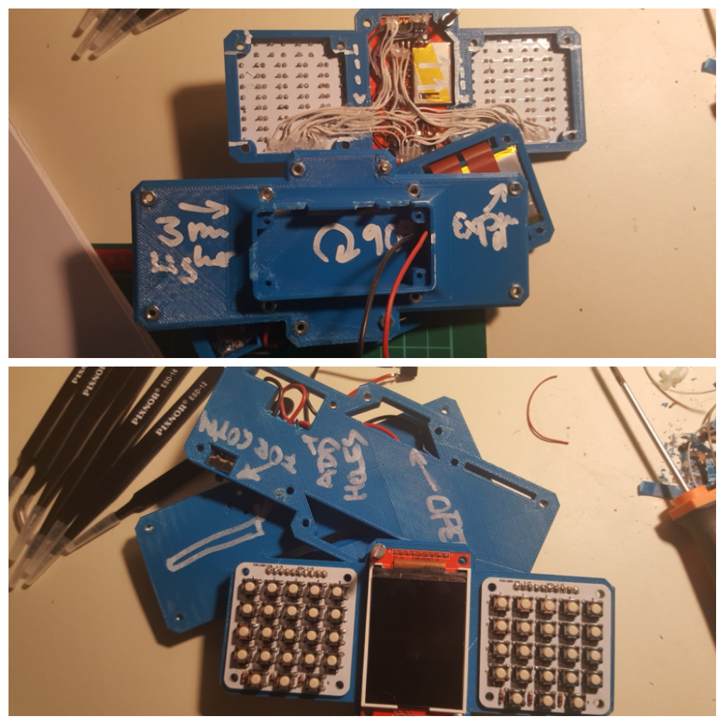
You have to 3D print the parts and have the boards for the keyboards ready
start with soldering the diodes to the keyboards, then the tactile button switches
Connect the two PCF8574 to the keyboards (also join together the row pins) and set the address pins differently.
Create an account to leave a comment. Already have an account? Log In.
I'm sure a man of your ilk and skill could fudge one if the cable doesn't come with it :-)
To be honest i reckon a full length cable would be a nightmare to fit into a project so small.
maybe I'll do another one that then is a foldable, then I will definitely add a camera ;) for now the case is designed in a very 'functional' way, not so much with aesthetics in mind... we'll see, first I would have to get the pi zero camera cable :)
What driver are you using for the display? I'm looking at project with rpi zero, this display and sound output via PWM pins on GPIO13 and GPIO18. Unfortunately, https://github.com/notro/fbtft uses GPIO18 as backlight control for this small ILI9340 display (configuration adafruit 2.2) and rebuilding it all looks like PITA, so I'm collecting other clues.
so far I only used a python example to write an image... Pin18 is also used on @ajlitt wifi hat, so I wasnt looking into sound.
Thank you. Looks like I need three PWM pins and have only two of them, uhm. On/off for backlight should be enough.
Maybe use a potentiometer like the Game Boy used for contrast.
Seems like you don't have to recompile stuff, you can modprobe the pins and the PWM pins for the sound output are still free.
http://marcosgildavid.blogspot.de/2014/02/getting-ili9341-spi-screen-working-on.html
That makes things easier. Thanks for pointing this out.
I like the 3D printed case. The various compartments for wires and boards are somewhat reminiscent of the milled aluminum covers that enclose some RF circuits.
it's more a happy little accident, but I like it none the less :) I wanted the battery to be protected and the usb charging board to be fixed in the case because of all the plugging in and out of the cable. I'll have to update the 3D files soon, before uploading them.
You really need to stop making projects like this, I'm easily summoned these days ha ha!
In all seriousness it's great how it's taking shape. I've always been hung up on a gameboy style handheld but this is much better; plenty of functionality without being bulky or cumbersome to wield.
I can't wait to see the finished article!
The call in here https://hackaday.io/page/2325-keyboards-please was because of this project? Looks like you've chosen the most future-proof and repeatable solution, though not the best one. I fully understand.
I'm very curious how this one turns out.
It was mainly because I wanted a PI zero portable, so yes :) Those buttons you were linking are perfect for this! They're easy to press and everything. I want to revisit the design to make it double sided with Letters on the silk print. I wasn't sure though that I'd really make it a project at first, that's why I made the page.
I hope I can make this a more 'programmers friendly' device, rather than a gaming console, so I wanted a keyboard.
So, you bought the particular keys from TME? Looks white, so the ones with smallest actuating force. Are you planning to give some keycaps/encapsulation/whatever to the keys?
I entered the "me too" crowd and bought the pi zero, pimoroni went out of stock shortly after my order :-) with the idea of building portable pi zero something. I have long history of portable computers (along with device programmers), with variable (generally low, though) degree of usefulness.
The display is really the cheap SPI 320x240?
well these are the same keys, but I've bought them a tat bit cheaper on ebay. They're indeed white, I wanted the lowest force just to be sure and not wonder.
I have 5 PI zeros now, thx to social engineering at the makerFaire Berlin and repeated orders at pimoroni and felt bad when I told the pimoroni guys that I haven't actually done anything with them yet. There's always a small barrier in my head where I don't want to "waste" boards and the PI zero might be cheap but also hard to get. So I will keep this modular as far as I can, no heavy soldering on the PI.
I hope I can get an AVR programmer / other proggers on there as well, I took some inspiration from your projects.
It is indeed the ILI9340 SPI 320x240 display. I'll get bigger displays soon, but right now I'm quite happy with the general size.
Become a member to follow this project and never miss any updates
 ElectronicABC

Congrats on making the finalist list mate!
You'll have to somehow work that Pi Camera into this now :-)