The idea of this project is to make an amplifier that can be customised. Something that annoys me with most amplifiers is that the input names are limited what the designer thought they should be. My home theatre amp has a BluRay input, a DVD/BluRay input, a Game input and so on. While I have one BluRay player, I don't have another and certainly don't have a DVD any more. So the "DVD/BluRay" is actually connected to my media player, but I can't change the name. It is a little thing but something that has always bugged me.
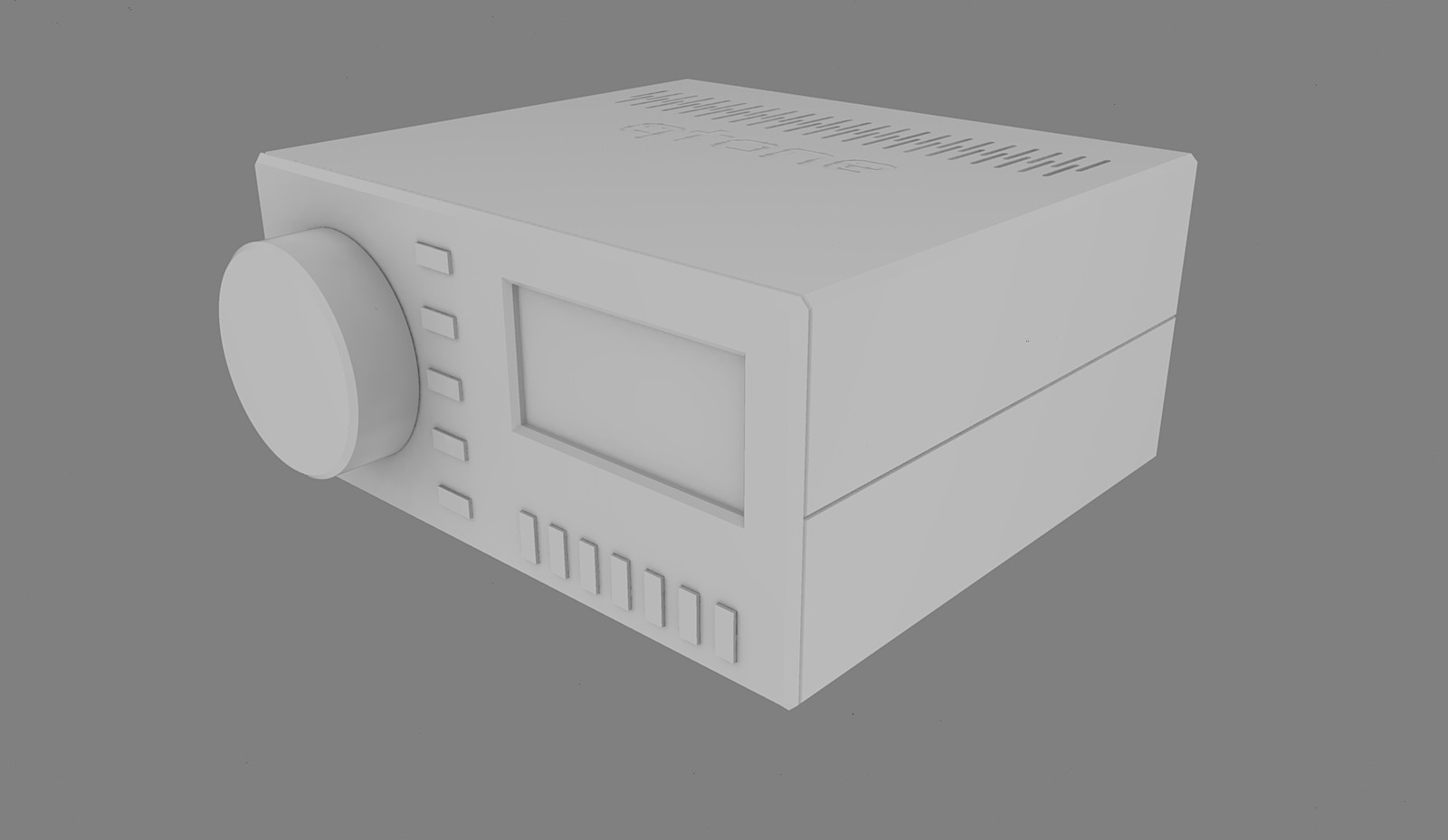
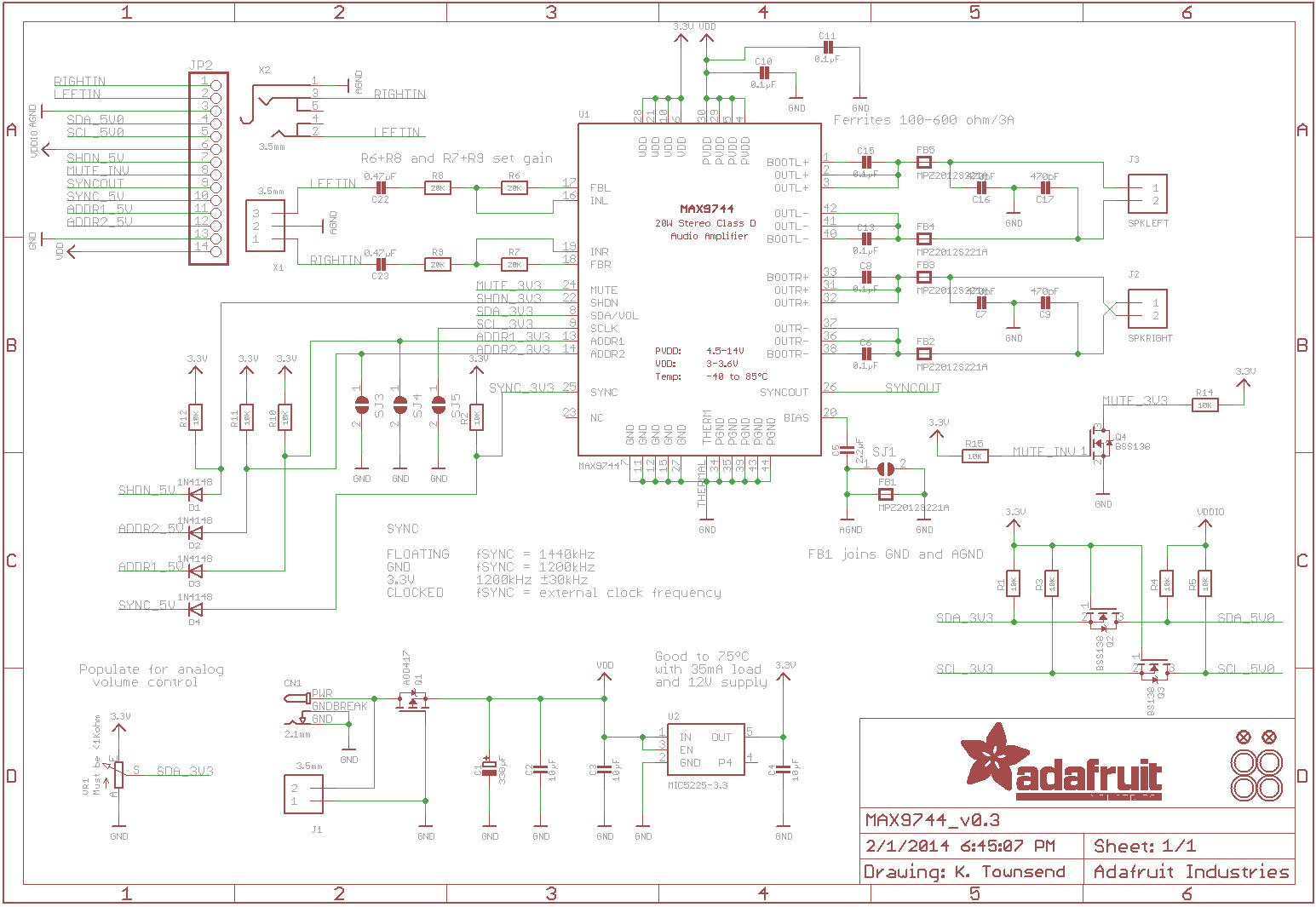
This is a 2 channel amplifier that I designed and made for my slowly expanding "physical media" equipment (so far a tape cassette, DAT, minidisc, vinyl and a RaspberryPi based network media player). As my equipment list grew I needed more than the little powered speakers I was using. I had a MAX9744 based 20W amplifier board by Adafruit that was for a failed project to make a set of powered speakers so that became the basis of the amplifier. the MAX has a few nice features. Firstly it is a digital amp, making it very energy efficient. Secondly it can control the the volume internally, either by using an external potentiometer or via I2C.
Initially I had it running in analogue mode but with the increasing devices I needed a way to switch between them. A little research and I came across the TDA7439DS. This little chip not only has 4 switchable inputs, it also has a 3 way tone control, balance, volume and is controllable via I2C. This opened up the option to use a microcontroller to govern all the parts. Given I have the most experience with the Arduino I went with a Nano as it was something I had on hand and was reasonably small.
So I designed a circuit for the TDA chip that would allow it to connect to the Adafruit amplifier board, the 4 inputs and the Arduino Nano. The Nano then had another board that connected to 5 buttons for dealing with power and the tone and balance controls. It also had a satellite PCB that connects to the input selector buttons and finally a 16x2 LCD character display with an I2C backpack.
Another thing I wanted was to have an output for a VU Visualiser (I refrain from calling it a 'meter' as it isn't calibrated. It is mostly for the flashy lights!) and another output so the currently selected input could be recorded on to a tape cassette. The TDA chip has two outputs, one just after the input selector and the second output after tone controls. The tape output comes from the output just after the multiplexer so it is an exact recreation of the input. The 'VU meter' is taken from the second output that is fed into the amplifier so it shows the actual signal being amplified.
One issue would have been if the TDA chip was controlling the volume, as lowering the volume would make the VU meter also drop down in its response. Fortunately the MAX chip, as we said above, has it's own volume control, that means the output to the VU meter isn't affected by lowering the volume as it happens inside the MAX chip.
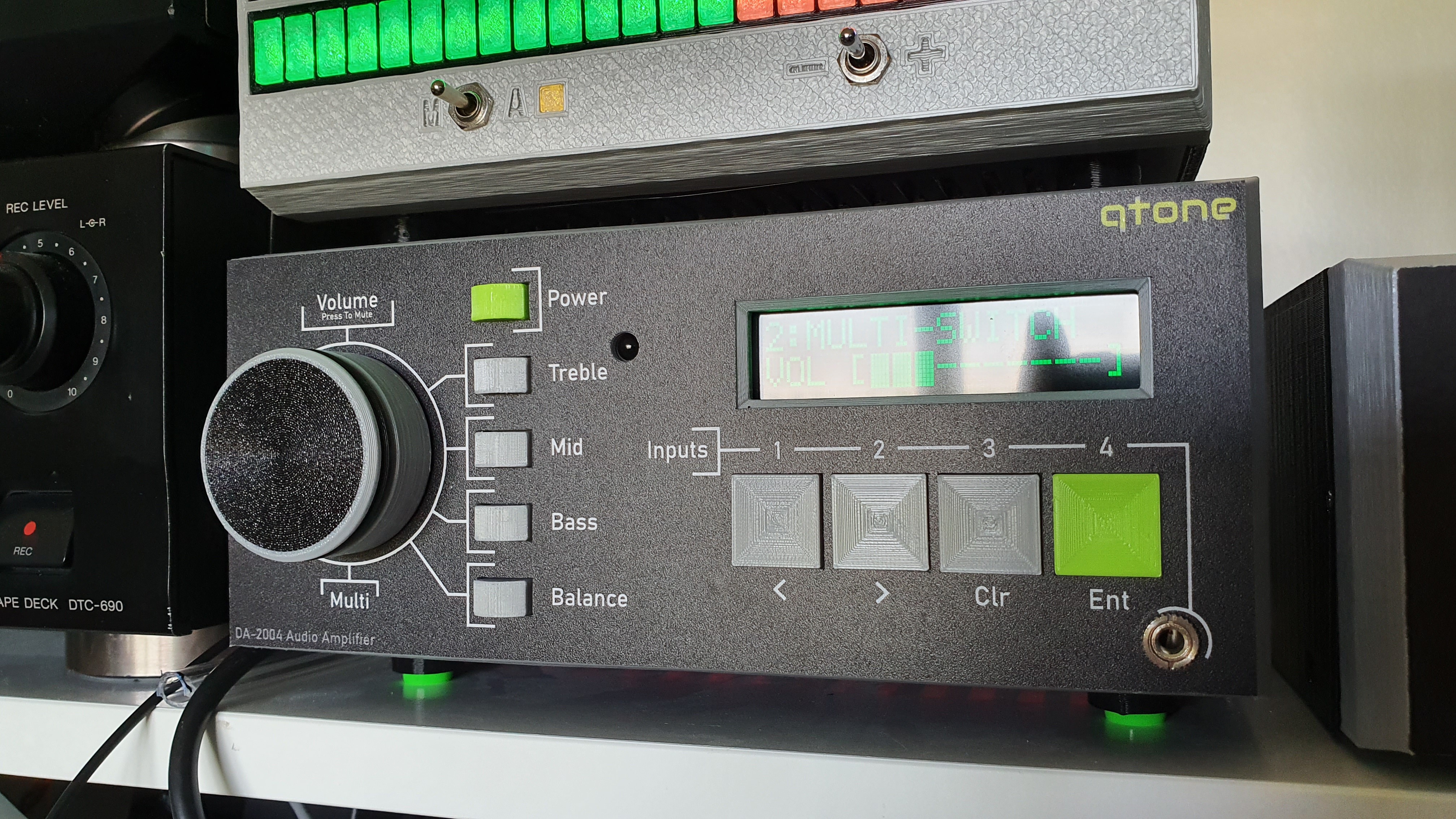
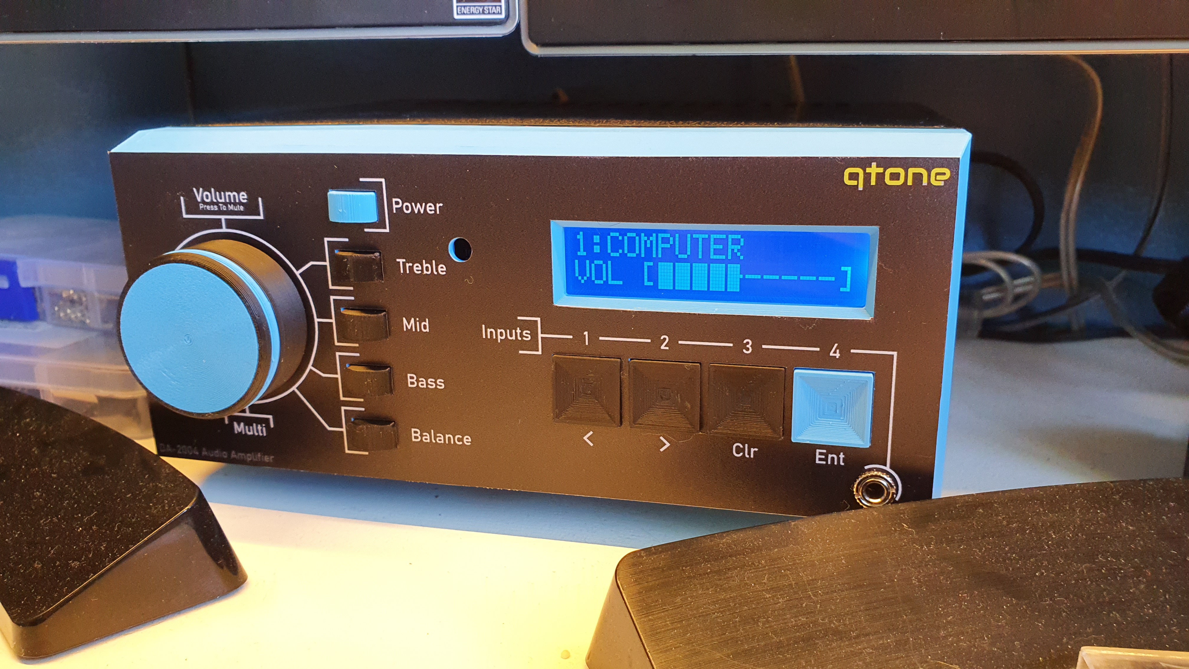
The LCD display is used to show the current input selected and the current volume level (or if it is muted). The inputs can all be named up to 14 characters which are stored in the Arduino's EEPROM (along with the current volume, tone and balance settings and the last selected input). Meaning even if powered down it will retain it's settings. All of this is controlled by the buttons and a rotary encoder.
 smartroad

Hi, I have a question, how can I return to Volume control with TDA7439. I don't want to use the Volume change via the MAX9744 amplifier.